France and Lebanon, countries that house a diversity of cultures. This heterogeneity has allowed me to develop the ability to understand and absorb complex and diverse contexts. My interest in determining how to use mechanical principles to analyze and design for the human body inspired me to pursue a bachelor's degree in Biomedical Engineering. I gained experience in a diversity of fields involving design, engineering, and finance and now aim to expand the skills I have acquired thus far by advancing my education in design. Experience Installation Engineer Investment Banking Intern Architecture Intern Automotive Design Intern Karl Storz EMG Bank Audi Private Bank GM Architects Groupe D3 09/19 - 10/20 01/19 - 06/19 09/18 - 12/18 09/17 - 10/17 Education Intro to Architectural Design BEng Biomedical Engineering French Baccalaureate Rhode Island School of Design University of Surrey Grand Lycee Franco Libanais 06/18 - 08/18 09/15 - 06/18 09/06 - 07/15 Acrobat ANSYS AutoCAD Illustrator InDesign Microsoft Office Photoshop Rhinoceros V6 Solid Edge Arabic English French Arduino Matlab Python e-mail phone Linkedin [email protected] +961 3 087 419 linkedin.com/in/tarekcmahmoud Softwares Languages Contact
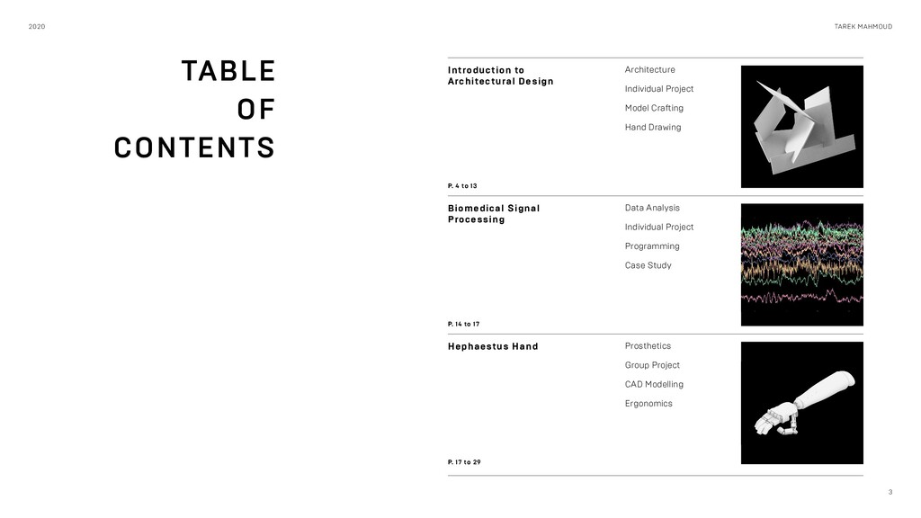
Design Architecture Individual Project Model Crafting Hand Drawing P. 4 to 13 Hephaestus Hand Prosthetics Group Project CAD Modelling Ergonomics P. 17 to 29 Biomedical Signal Processing Data Analysis Individual Project Programming Case Study P. 14 to 17
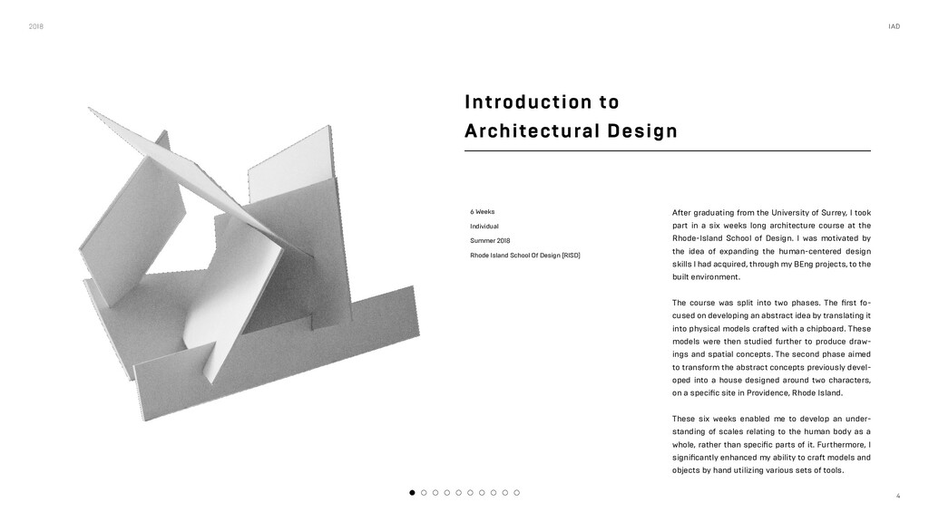
Rhode Island School Of Design [RISD] After graduating from the University of Surrey, I took part in a six weeks long architecture course at the Rhode-Island School of Design. I was motivated by the idea of expanding the human-centered design skills I had acquired, through my BEng projects, to the built environment. The course was split into two phases. The first fo- cused on developing an abstract idea by translating it into physical models crafted with a chipboard. These models were then studied further to produce draw- ings and spatial concepts. The second phase aimed to transform the abstract concepts previously devel- oped into a house designed around two characters, on a specific site in Providence, Rhode Island. These six weeks enabled me to develop an under- standing of scales relating to the human body as a whole, rather than specific parts of it. Furthermore, I significantly enhanced my ability to craft models and objects by hand utilizing various sets of tools. 2018 IAD
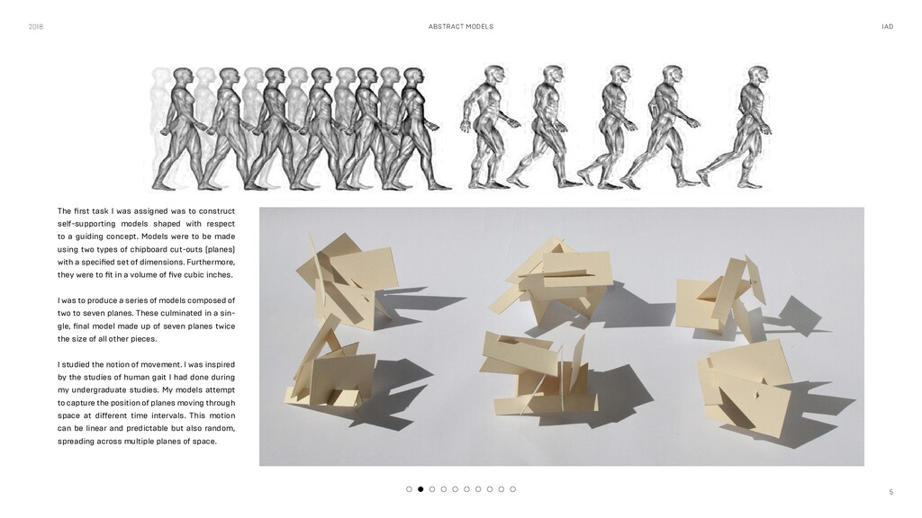
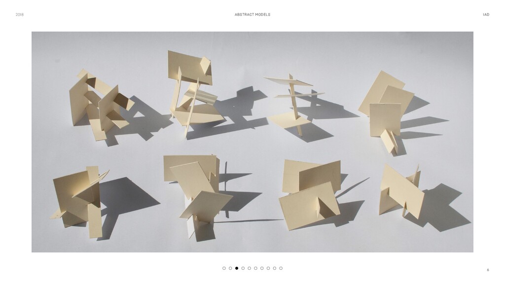
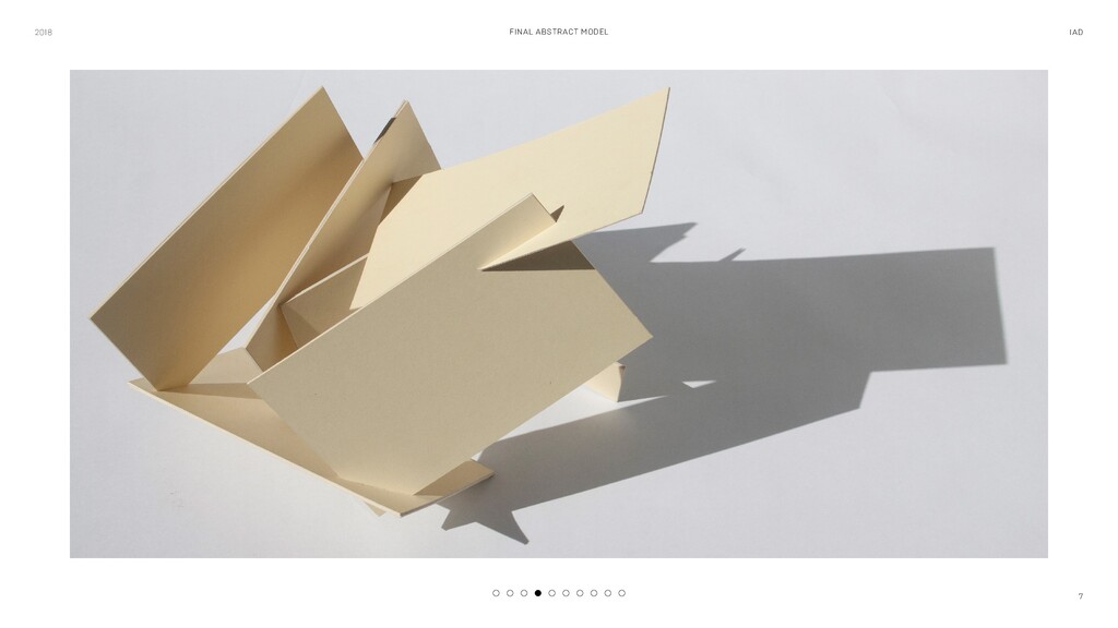
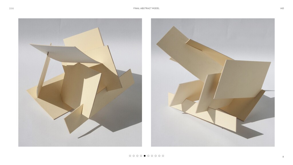
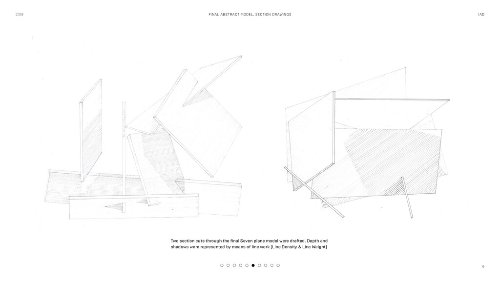
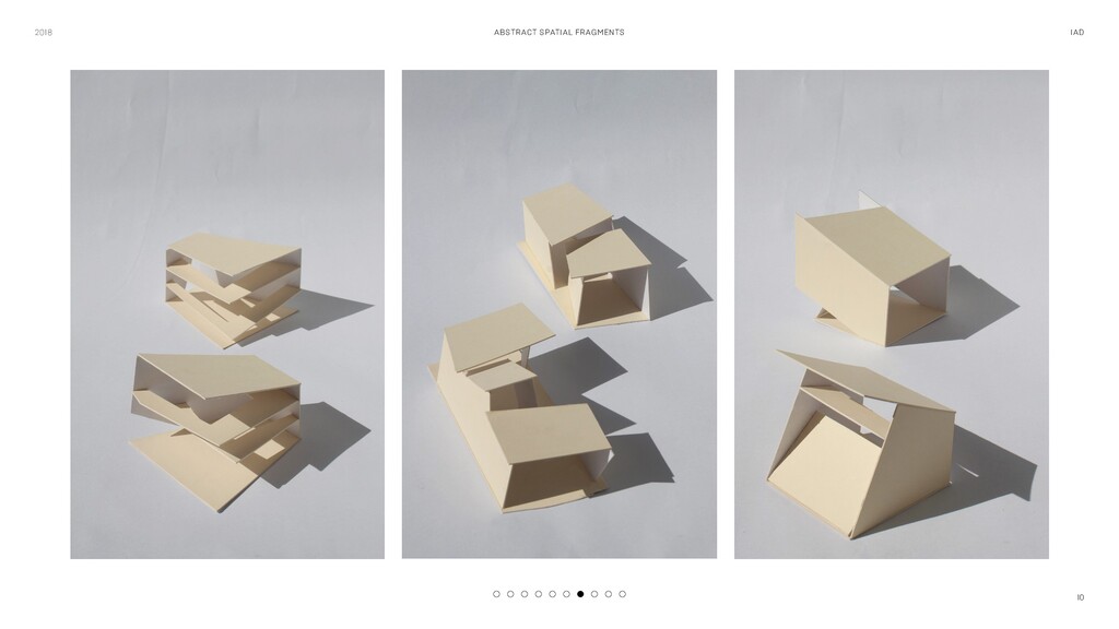
assigned was to construct self-supporting models shaped with respect to a guiding concept. Models were to be made using two types of chipboard cut-outs (planes) with a specified set of dimensions. Furthermore, they were to fit in a volume of five cubic inches. I was to produce a series of models composed of two to seven planes. These culminated in a sin- gle, final model made up of seven planes twice the size of all other pieces. I studied the notion of movement. I was inspired by the studies of human gait I had done during my undergraduate studies. My models attempt to capture the position of planes moving through space at different time intervals. This motion can be linear and predictable but also random, spreading across multiple planes of space.
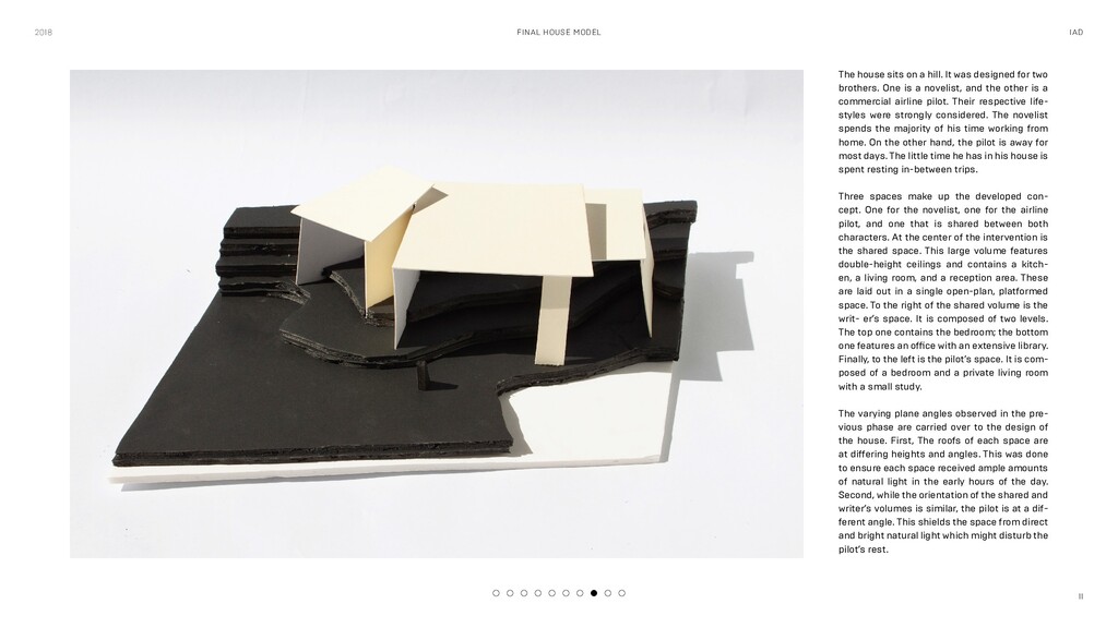
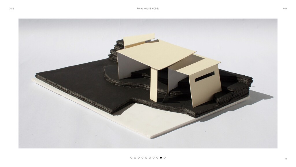
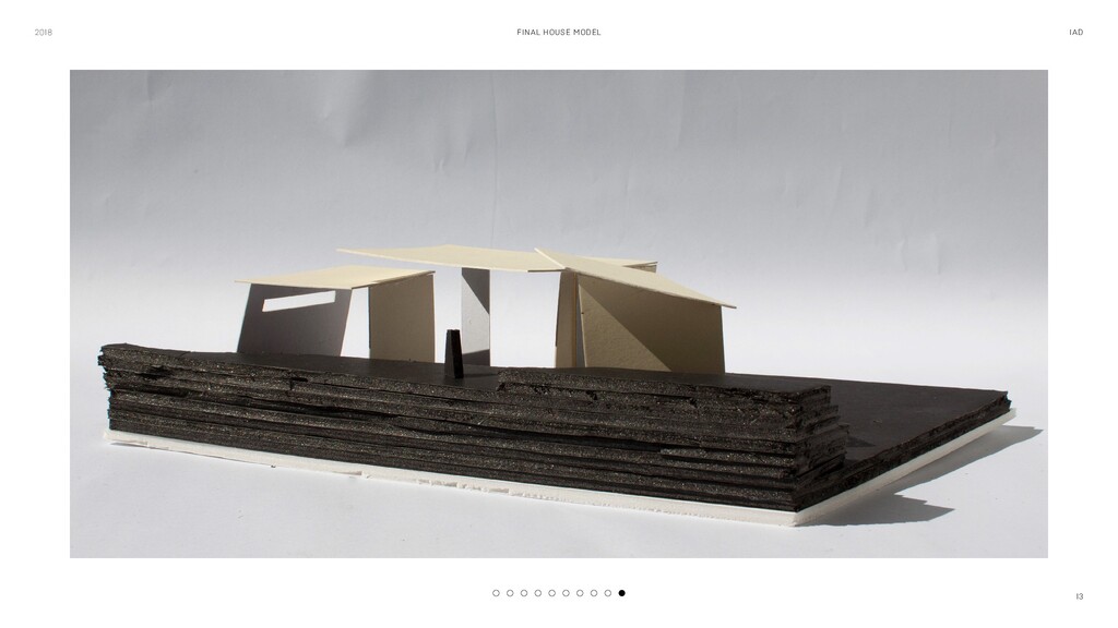
a hill. It was designed for two brothers. One is a novelist, and the other is a commercial airline pilot. Their respective life- styles were strongly considered. The novelist spends the majority of his time working from home. On the other hand, the pilot is away for most days. The little time he has in his house is spent resting in-between trips. Three spaces make up the developed con- cept. One for the novelist, one for the airline pilot, and one that is shared between both characters. At the center of the intervention is the shared space. This large volume features double-height ceilings and contains a kitch- en, a living room, and a reception area. These are laid out in a single open-plan, platformed space. To the right of the shared volume is the writ- er’s space. It is composed of two levels. The top one contains the bedroom; the bottom one features an office with an extensive library. Finally, to the left is the pilot’s space. It is com- posed of a bedroom and a private living room with a small study. The varying plane angles observed in the pre- vious phase are carried over to the design of the house. First, The roofs of each space are at differing heights and angles. This was done to ensure each space received ample amounts of natural light in the early hours of the day. Second, while the orientation of the shared and writer’s volumes is similar, the pilot is at a dif- ferent angle. This shields the space from direct and bright natural light which might disturb the pilot’s rest.
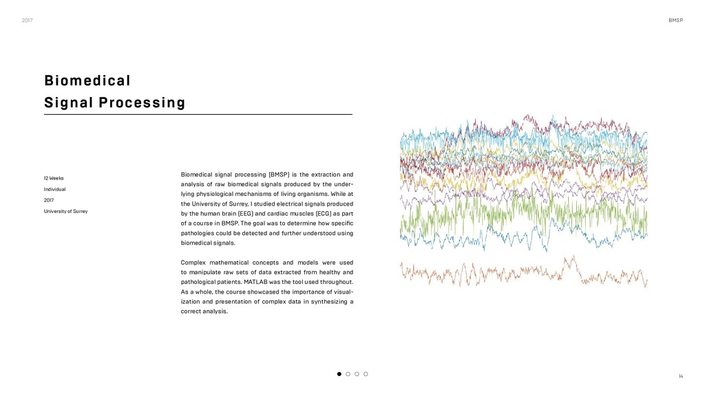
Surrey Biomedical signal processing (BMSP) is the extraction and analysis of raw biomedical signals produced by the under- lying physiological mechanisms of living organisms. While at the University of Surrey, I studied electrical signals produced by the human brain (EEG) and cardiac muscles (ECG) as part of a course in BMSP. The goal was to determine how specific pathologies could be detected and further understood using biomedical signals. Complex mathematical concepts and models were used to manipulate raw sets of data extracted from healthy and pathological patients. MATLAB was the tool used throughout. As a whole, the course showcased the importance of visual- ization and presentation of complex data in synthesizing a correct analysis. 2017 BMSP
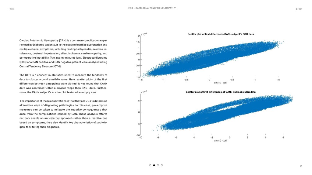
Neuropathy (CAN) is a common complication expe- rienced by Diabetes patients. It is the cause of cardiac dysfunction and multiple clinical symptoms, including resting tachycardia, exercise in- tolerance, postural hypotension, silent ischemia, cardiomyopathy, and perioperative instability. Two, twenty minutes long, Electrocardiograms (ECG) of a CAN positive and CAN negative patient were analyzed using Central Tendency Measure (CTM). The CTM is a concept in statistics used to measure the tendency of data to cluster around a middle value. Here, scatter plots of the first differences between data points were plotted. It was found that CAN+ data was contained within a smaller range than CAN- data. Further- more, the CAN+ subject’s scatter plot featured an empty area. The importance of these observations is that they allow us to determine alternative ways of diagnosing pathologies. In this case, pre-emptive measures can be taken to mitigate the negative consequences that arise from the complications caused by CAN. These analysis efforts not only enable an anticipatory approach rather than a reactive one based on symptoms, they also identify key characteristics of patholo- gies, facilitating their diagnosis.
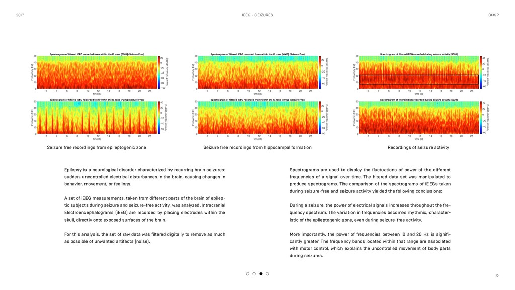
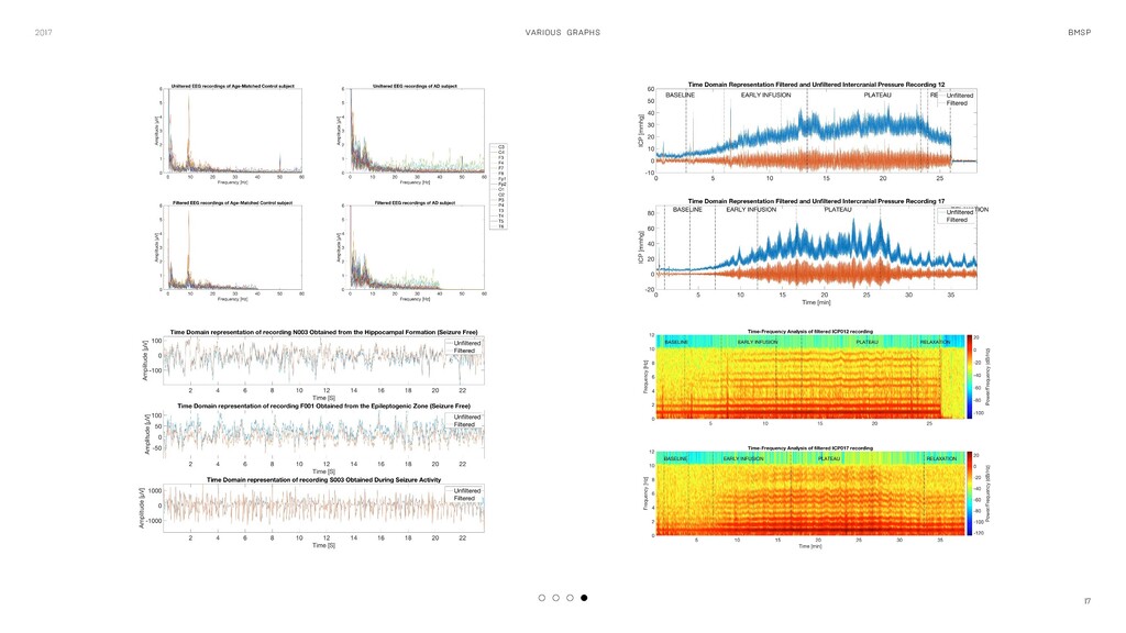
disorder characterized by recurring brain seizures: sudden, uncontrolled electrical disturbances in the brain, causing changes in behavior, movement, or feelings. A set of iEEG measurements, taken from different parts of the brain of epilep- tic subjects during seizure and seizure-free activity, was analyzed. Intracranial Electroencephalograms (iEEG) are recorded by placing electrodes within the skull, directly onto exposed surfaces of the brain. For this analysis, the set of raw data was filtered digitally to remove as much as possible of unwanted artifacts (noise). Spectrograms are used to display the fluctuations of power of the different frequencies of a signal over time. The filtered data set was manipulated to produce spectrograms. The comparison of the spectrograms of iEEGs taken during seizure-free and seizure activity yielded the following conclusions: During a seizure, the power of electrical signals increases throughout the fre- quency spectrum. The variation in frequencies becomes rhythmic, character- istic of the epileptogenic zone, even during seizure-free activity. More importantly, the power of frequencies between 10 and 20 Hz is signifi- cantly greater. The frequency bands located within that range are associated with motor control, which explains the uncontrolled movement of body parts during seizures. Seizure free recordings from epileptogenic zone Seizure free recordings from hippocampal formation Recordings of seizure activity
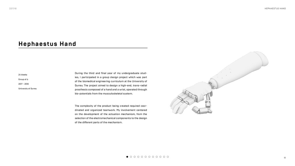
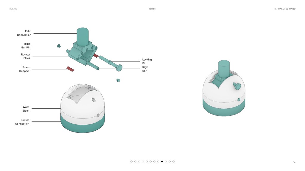
2018 University of Surrey During the third and final year of my undergraduate stud- ies, I participated in a group design project which was part of the biomedical engineering curriculum at the University of Surrey. The project aimed to design a high-end, trans-radial prosthesis composed of a hand and a wrist, operated through bio-potentials from the musculoskeletal system. The complexity of the product being created required coor- dinated and organized teamwork. My involvement centered on the development of the actuation mechanism, from the selection of the electromechanical components to the design of the different parts of the mechanism. 2017/18 HEPHAESTUS HAND
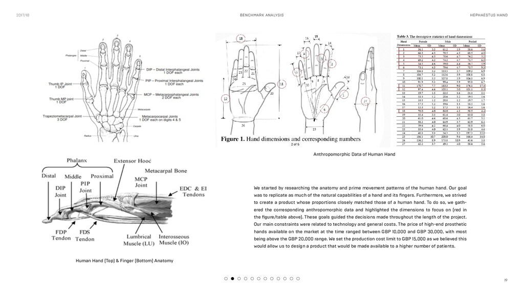
Finger (Bottom) Anatomy Anthropomorphic Data of Human Hand We started by researching the anatomy and prime movement patterns of the human hand. Our goal was to replicate as much of the natural capabilities of a hand and its fingers. Furthermore, we strived to create a product whose proportions closely matched those of a human hand. To do so, we gath- ered the corresponding anthropomorphic data and highlighted the dimensions to focus on (red in the figure/table above). These goals guided the decisions made throughout the length of the project. Our main constraints were related to technology and general costs. The price of high-end prosthetic hands available on the market at the time ranged between GBP 10,000 and GBP 30,000, with most being above the GBP 20,000 range. We set the production cost limit to GBP 15,000 as we believed this would allow us to design a product that would be made available to a higher number of patients.
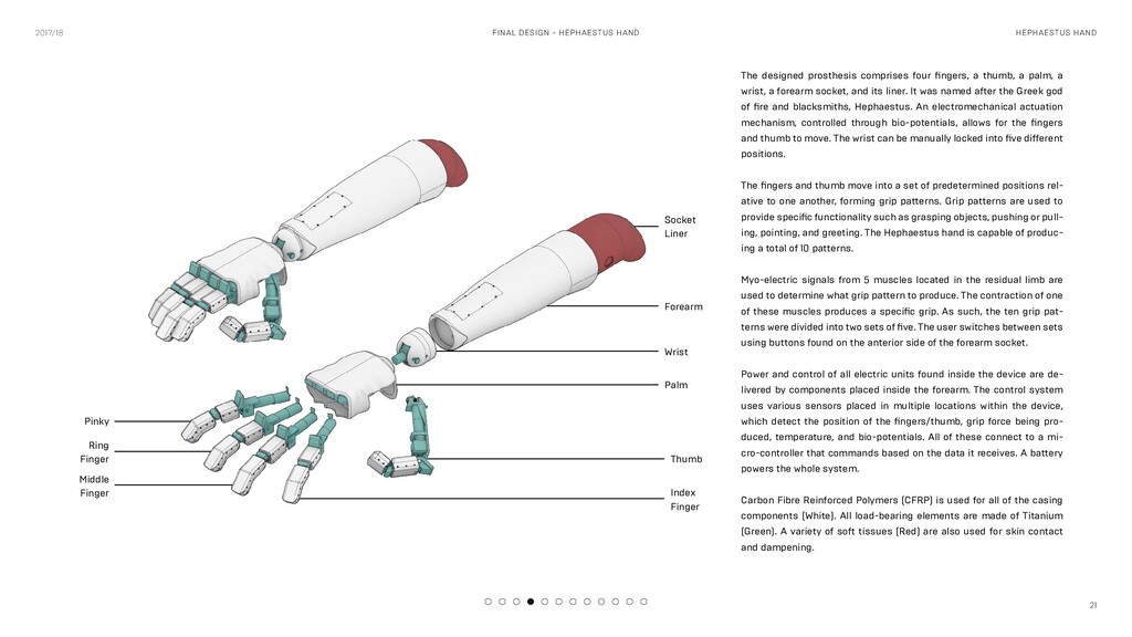
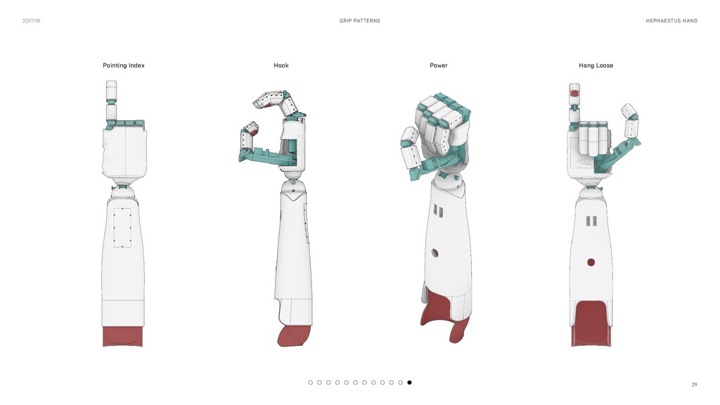
designed prosthesis comprises four fingers, a thumb, a palm, a wrist, a forearm socket, and its liner. It was named after the Greek god of fire and blacksmiths, Hephaestus. An electromechanical actuation mechanism, controlled through bio-potentials, allows for the fingers and thumb to move. The wrist can be manually locked into five different positions. The fingers and thumb move into a set of predetermined positions rel- ative to one another, forming grip patterns. Grip patterns are used to provide specific functionality such as grasping objects, pushing or pull- ing, pointing, and greeting. The Hephaestus hand is capable of produc- ing a total of 10 patterns. Myo-electric signals from 5 muscles located in the residual limb are used to determine what grip pattern to produce. The contraction of one of these muscles produces a specific grip. As such, the ten grip pat- terns were divided into two sets of five. The user switches between sets using buttons found on the anterior side of the forearm socket. Power and control of all electric units found inside the device are de- livered by components placed inside the forearm. The control system uses various sensors placed in multiple locations within the device, which detect the position of the fingers/thumb, grip force being pro- duced, temperature, and bio-potentials. All of these connect to a mi- cro-controller that commands based on the data it receives. A battery powers the whole system. Carbon Fibre Reinforced Polymers (CFRP) is used for all of the casing components (White). All load-bearing elements are made of Titanium (Green). A variety of soft tissues (Red) are also used for skin contact and dampening. Middle Finger Ring Finger Pinky Thumb Palm Wrist Forearm Socket Liner Index Finger
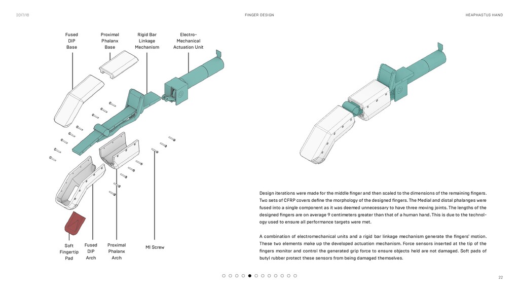
then scaled to the dimensions of the remaining fingers. Two sets of CFRP covers define the morphology of the designed fingers. The Medial and distal phalanges were fused into a single component as it was deemed unnecessary to have three moving joints. The lengths of the designed fingers are on average 9 centimeters greater than that of a human hand. This is due to the technol- ogy used to ensure all performance targets were met. A combination of electromechanical units and a rigid bar linkage mechanism generate the fingers' motion. These two elements make up the developed actuation mechanism. Force sensors inserted at the tip of the fingers monitor and control the generated grip force to ensure objects held are not damaged. Soft pads of butyl rubber protect these sensors from being damaged themselves. 2017/18 HEAPHASTUS HAND FINGER DESIGN Fused DIP Arch Soft Fingertip Pad Proximal Phalanx Arch M1 Screw Fused DIP Base Proximal Phalanx Base Rigid Bar Linkage Mechanism Electro- Mechanical Actuation Unit
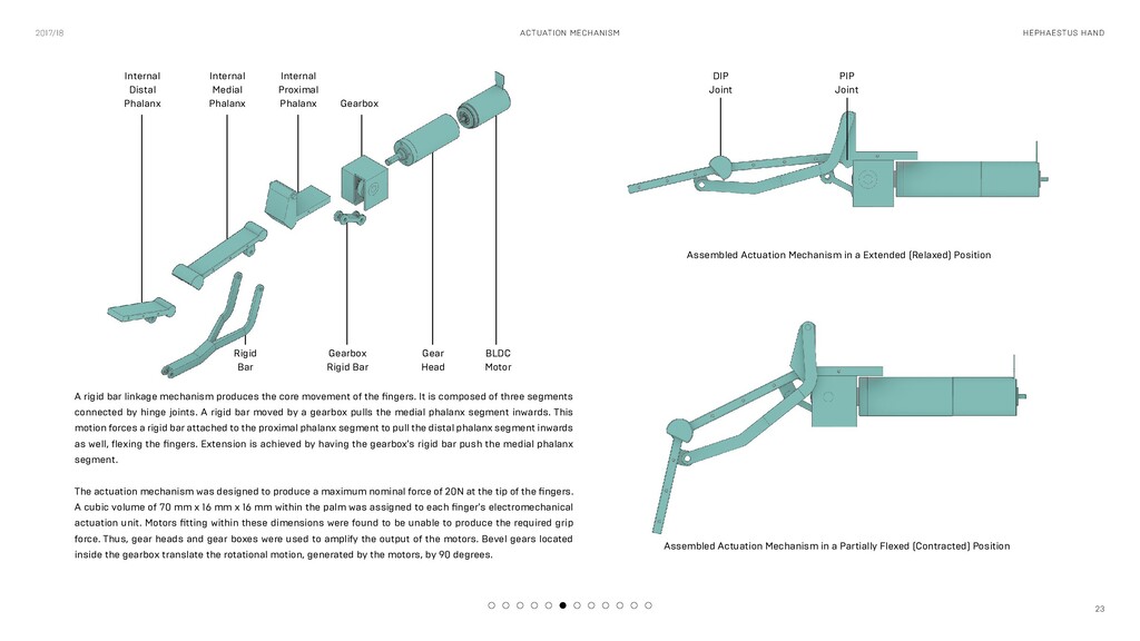
mechanism produces the core movement of the fingers. It is composed of three segments connected by hinge joints. A rigid bar moved by a gearbox pulls the medial phalanx segment inwards. This motion forces a rigid bar attached to the proximal phalanx segment to pull the distal phalanx segment inwards as well, flexing the fingers. Extension is achieved by having the gearbox's rigid bar push the medial phalanx segment. The actuation mechanism was designed to produce a maximum nominal force of 20N at the tip of the fingers. A cubic volume of 70 mm x 16 mm x 16 mm within the palm was assigned to each finger's electromechanical actuation unit. Motors fitting within these dimensions were found to be unable to produce the required grip force. Thus, gear heads and gear boxes were used to amplify the output of the motors. Bevel gears located inside the gearbox translate the rotational motion, generated by the motors, by 90 degrees. Rigid Bar Internal Distal Phalanx Internal Medial Phalanx Internal Proximal Phalanx Gearbox Rigid Bar Gear Head Assembled Actuation Mechanism in a Extended (Relaxed) Position Assembled Actuation Mechanism in a Partially Flexed (Contracted) Position BLDC Motor Gearbox DIP Joint PIP Joint
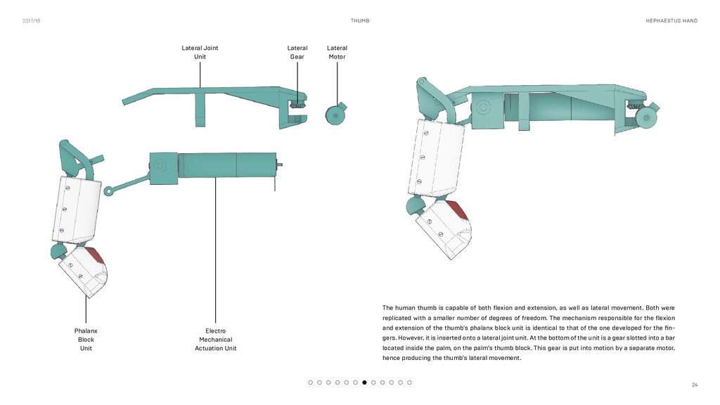
of both flexion and extension, as well as lateral movement. Both were replicated with a smaller number of degrees of freedom. The mechanism responsible for the flexion and extension of the thumb's phalanx block unit is identical to that of the one developed for the fin- gers. However, it is inserted onto a lateral joint unit. At the bottom of the unit is a gear slotted into a bar located inside the palm, on the palm's thumb block. This gear is put into motion by a separate motor, hence producing the thumb's lateral movement. Electro Mechanical Actuation Unit Phalanx Block Unit Lateral Joint Unit Lateral Motor Lateral Gear
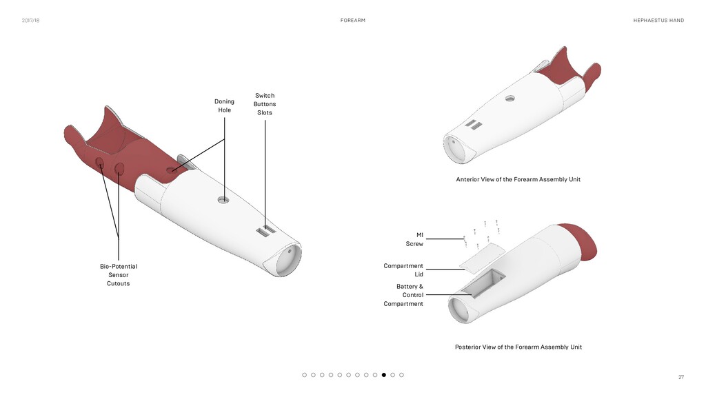
View of the Forearm Assembly Unit Posterior View of the Forearm Assembly Unit Bio-Potential Sensor Cutouts Doning Hole Switch Buttons Slots Battery & Control Compartment
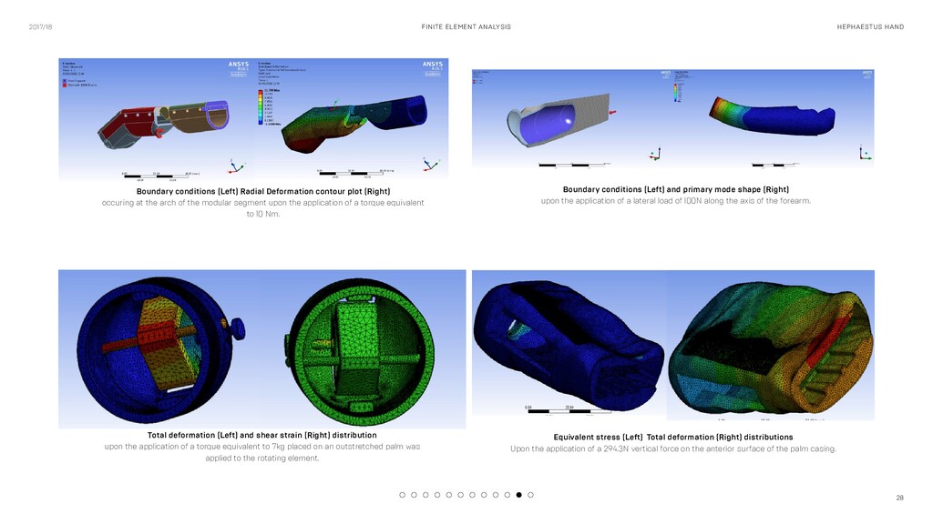
Radial Deformation contour plot (Right) occuring at the arch of the modular segment upon the application of a torque equivalent to 10 Nm. Boundary conditions (Left) and primary mode shape (Right) upon the application of a lateral load of 100N along the axis of the forearm. Total deformation (Left) and shear strain (Right) distribution upon the application of a torque equivalent to 7kg placed on an outstretched palm was applied to the rotating element. Equivalent stress (Left) Total deformation (Right) distributions Upon the application of a 294.3N vertical force on the anterior surface of the palm casing.


 tessaabrams
 minecr
 katarinadahlin
 sarafernandez
 schlessera
 dugsong
 codingconduct
 csswizardry
 techseoconnect
 baasie