Upgrade to Pro — share decks privately, control downloads, hide ads and more …

NMRV worm gearbox suppliers in New Delhi

Avatar for Univario Univario
February 12, 2025
9

NMRV worm gearbox suppliers in New Delhi

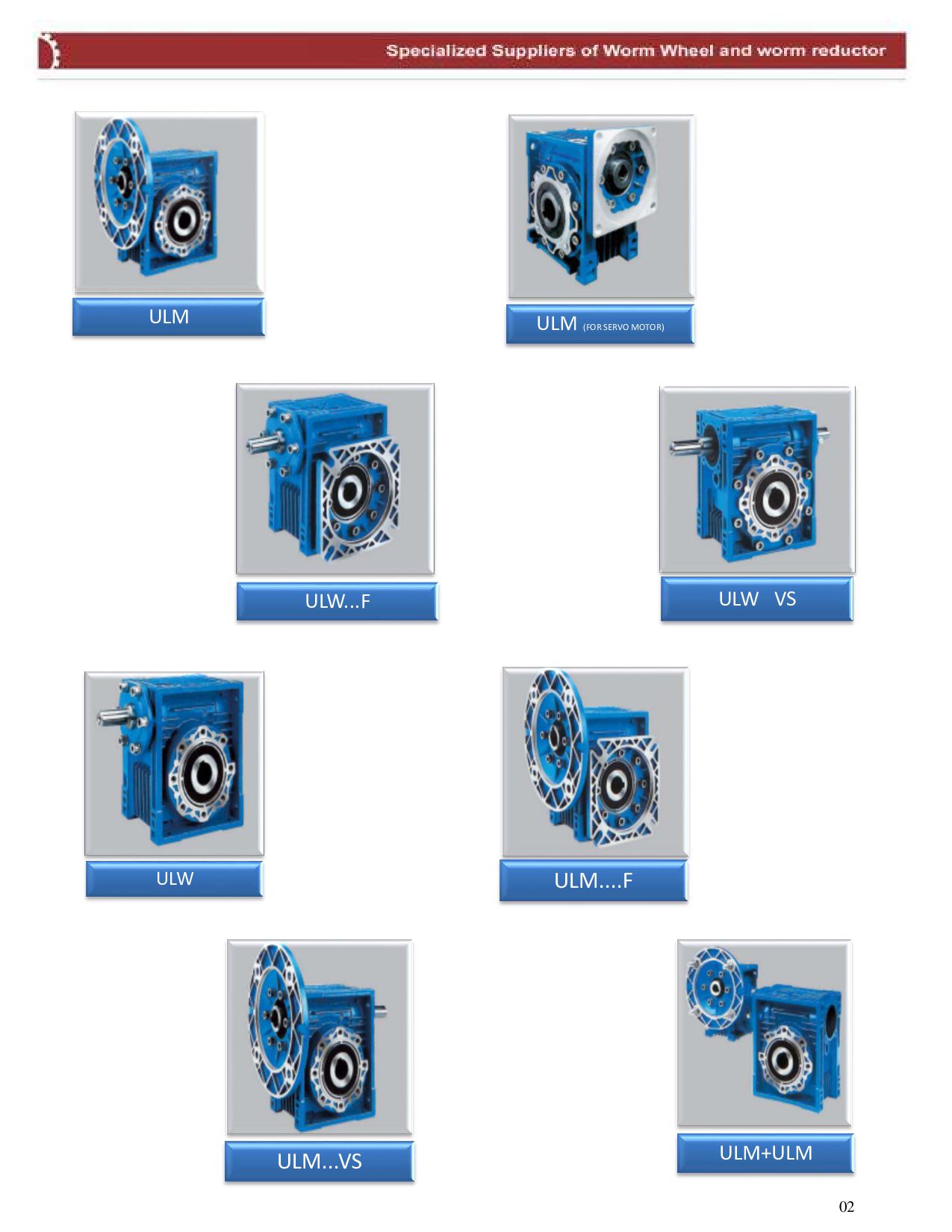
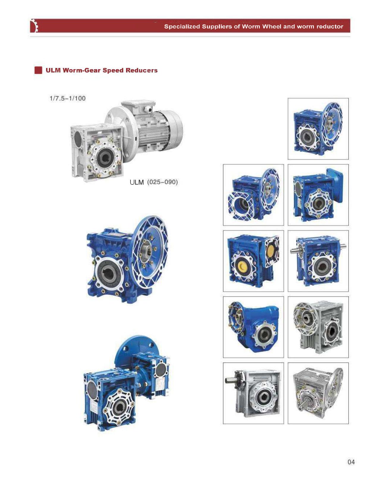
NMRV worm gearboxes are widely used in various industrial applications, including conveyors, packaging machines, and automation systems, due to their high efficiency, compact size, and durability. Several reputed suppliers in New Delhi offer high-quality NMRV worm gearboxes with different torque capacities and gear ratios to meet specific industrial needs. Key functions of the NMRV worm gearbox:

Compact and light: The aluminum case provides durability and light installation.
High efficiency: Low energy loss from the design of accurate transmission.
Low noise and smooth work: Suitable for applications that require minimum vibration.
Corrosion stability: Ideal for difficult media.
Several installation options: Available in leg, tedious, tree configurations.
Best suppliers of NMRV gearboxes in New Delhi:
Univario Transmission

Location: New Delia, dzhanakpuri
Product: High-performance NMRV gearbox in several configurations.
Website: www.univario.in

Avatar for Univario

Univario

February 12, 2025

Transcript

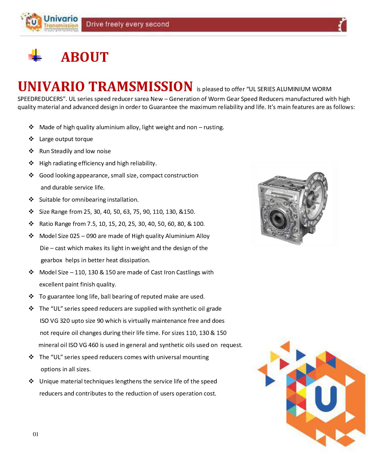
  1. ABOUT UNIVARIO TRAMSMISSION is pleased to offer “UL SERIES ALUMINIUM

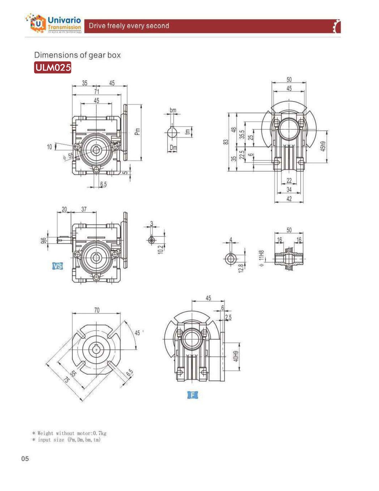
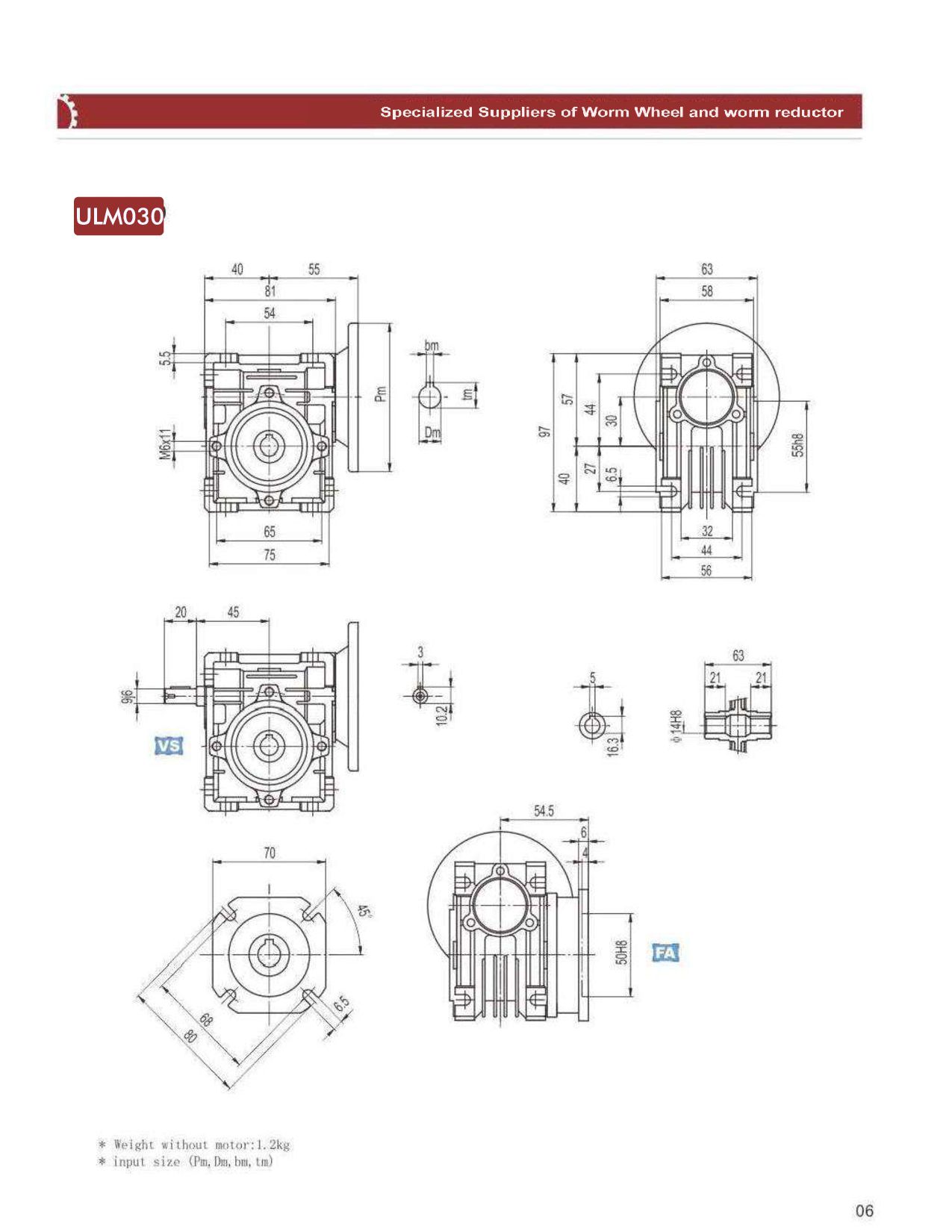
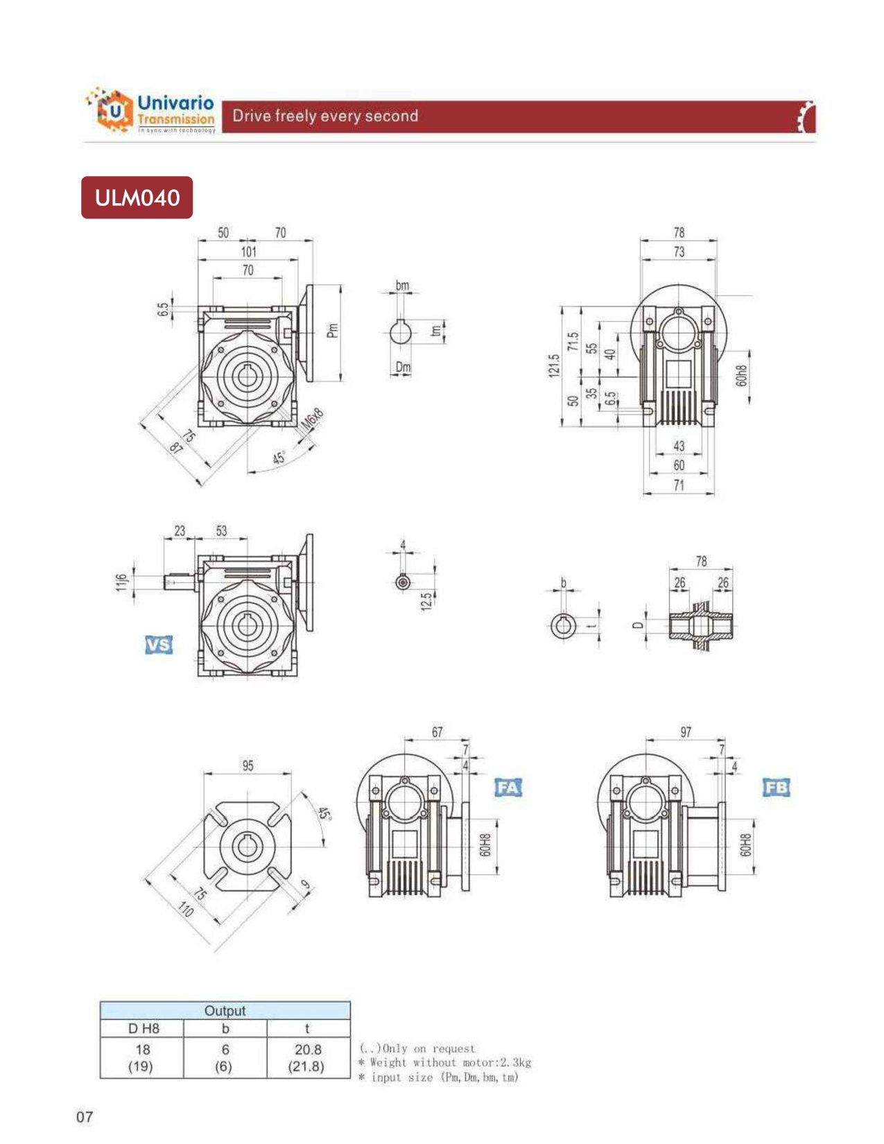
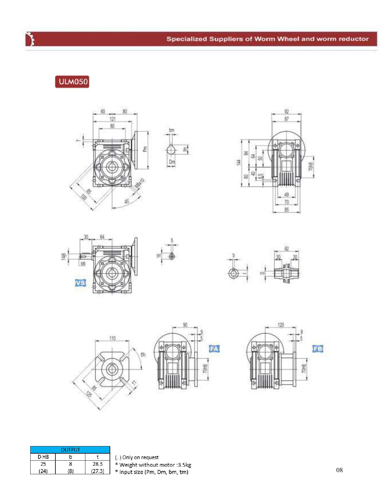
    WORM SPEEDREDUCERS”. UL series speed reducer sarea New – Generation of Worm Gear Speed Reducers manufactured with high quality material and advanced design in order to Guarantee the maximum reliability and life. It’s main features are as follows:  Made of high quality aluminium alloy, light weight and non – rusting.  Large output torque  Run Steadily and low noise  High radiating efficiency and high reliability.  Good looking appearance, small size, compact construction and durable service life.  Suitable for omnibearing installation.  Size Range from 25, 30, 40, 50, 63, 75, 90, 110, 130, &150.  Ratio Range from 7.5, 10, 15, 20, 25, 30, 40, 50, 60, 80, & 100.  Model Size 025 – 090 are made of High quality Aluminium Alloy Die – cast which makes its light in weight and the design of the gearbox helps in better heat dissipation.  Model Size – 110, 130 & 150 are made of Cast Iron Castlings with excellent paint finish quality.  To guarantee long life, ball bearing of reputed make are used.  The “UL” series speed reducers are supplied with synthetic oil grade ISO VG 320 upto size 90 which is virtually maintenance free and does not require oil changes during their life time. For sizes 110, 130 & 150 mineral oil ISO VG 460 is used in general and synthetic oils used on request.  The “UL” series speed reducers comes with universal mounting options in all sizes.  Unique material techniques lengthens the service life of the speed reducers and contributes to the reduction of users operation cost. 01
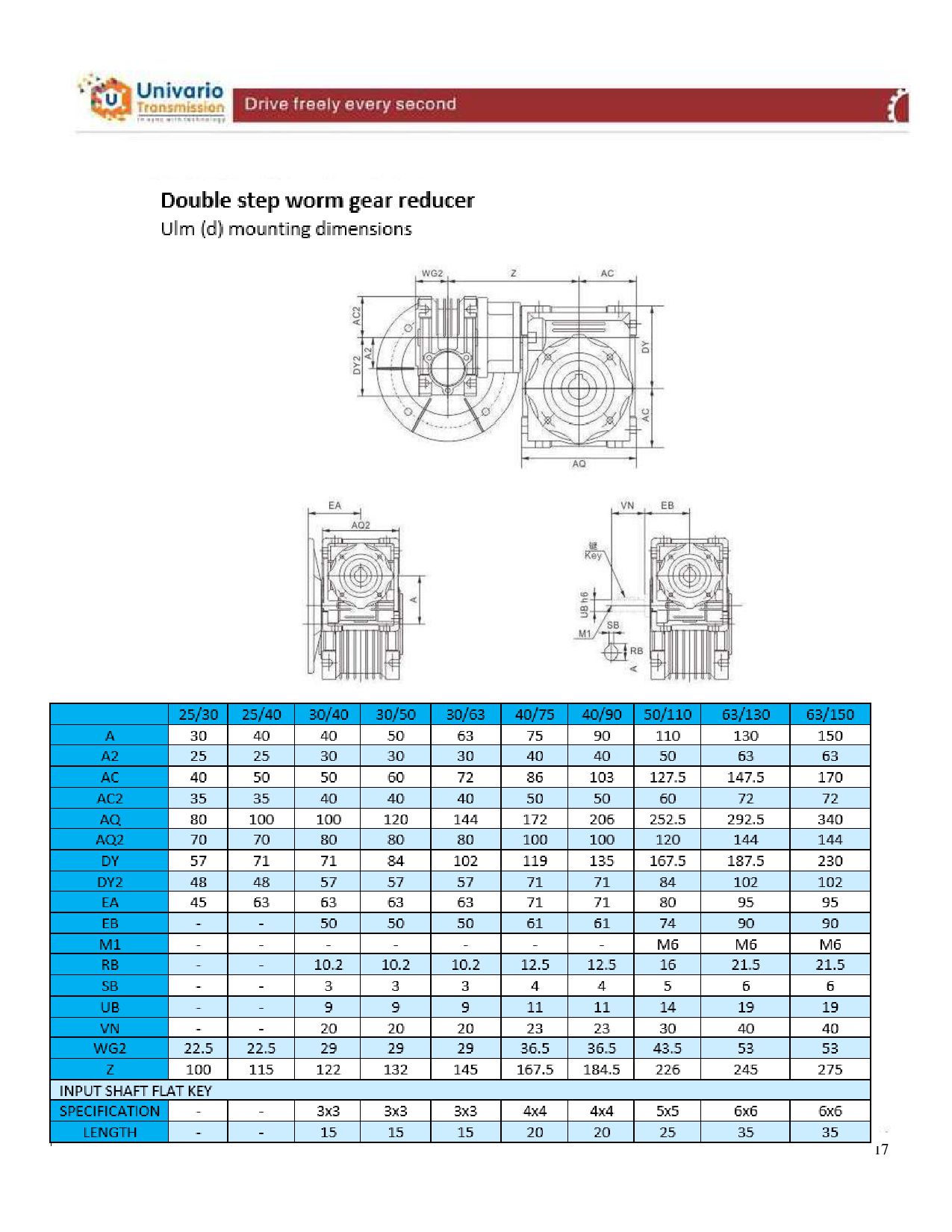
  2. 08

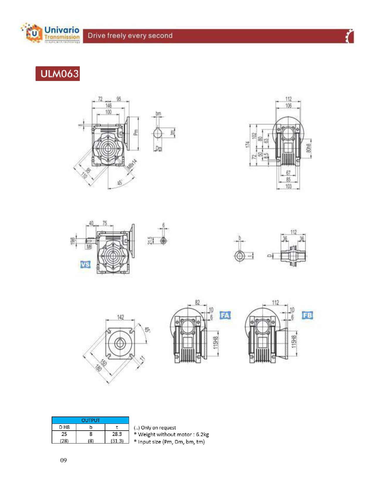
  3. 09

  4. 10

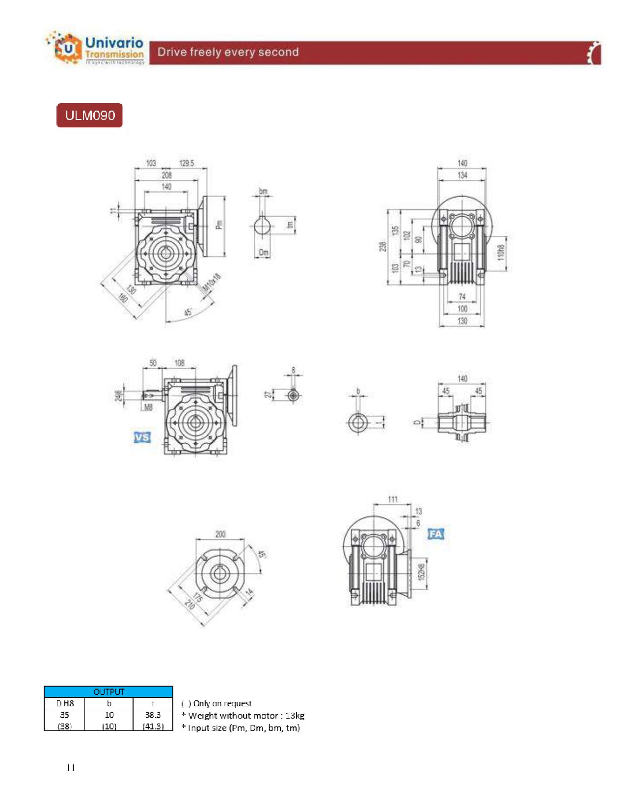
  5. 11

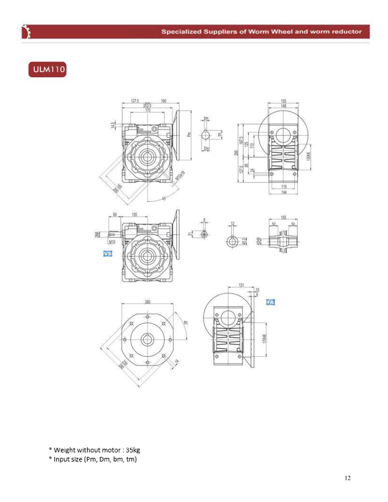
  6. 12

  7. 12

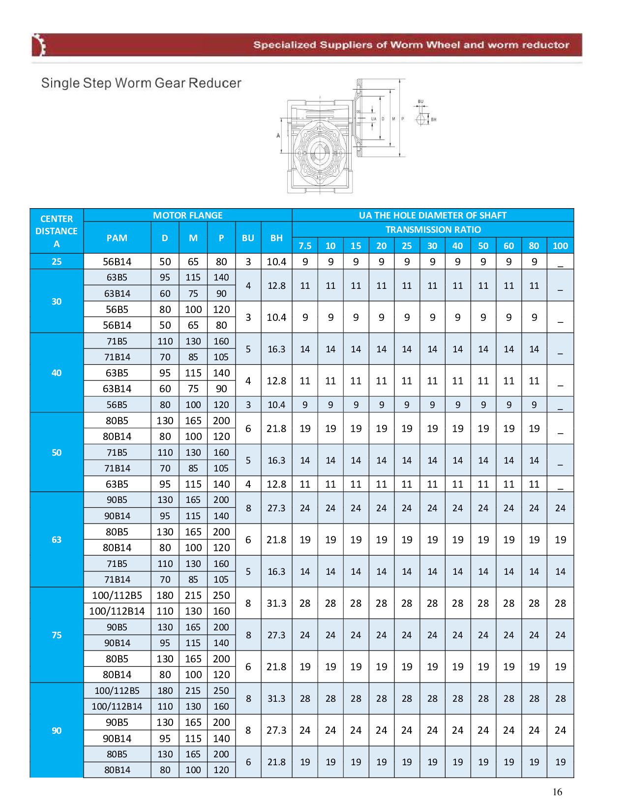
  8. CENTER DISTANCE A MOTOR FLANGE UA THE HOLE DIAMETER OF

    SHAFT PAM D M P BU BH TRANSMISSION RATIO 7.5 10 15 20 25 30 40 50 60 80 100 25 56B14 50 65 80 3 10.4 9 9 9 9 9 9 9 9 9 9 _ 30 63B5 95 115 140 4 12.8 11 11 11 11 11 11 11 11 11 11 _ 63B14 60 75 90 56B5 80 100 120 3 10.4 9 9 9 9 9 9 9 9 9 9 _ 56B14 50 65 80 40 71B5 110 130 160 5 16.3 14 14 14 14 14 14 14 14 14 14 _ 71B14 70 85 105 63B5 95 115 140 4 12.8 11 11 11 11 11 11 11 11 11 11 _ 63B14 60 75 90 56B5 80 100 120 3 10.4 9 9 9 9 9 9 9 9 9 9 _ 50 80B5 130 165 200 6 21.8 19 19 19 19 19 19 19 19 19 19 _ 80B14 80 100 120 71B5 110 130 160 5 16.3 14 14 14 14 14 14 14 14 14 14 _ 71B14 70 85 105 63B5 95 115 140 4 12.8 11 11 11 11 11 11 11 11 11 11 _ 63 90B5 130 165 200 8 27.3 24 24 24 24 24 24 24 24 24 24 24 90B14 95 115 140 80B5 130 165 200 6 21.8 19 19 19 19 19 19 19 19 19 19 19 80B14 80 100 120 71B5 110 130 160 5 16.3 14 14 14 14 14 14 14 14 14 14 14 71B14 70 85 105 75 100/112B5 180 215 250 8 31.3 28 28 28 28 28 28 28 28 28 28 28 100/112B14 110 130 160 90B5 130 165 200 8 27.3 24 24 24 24 24 24 24 24 24 24 24 90B14 95 115 140 80B5 130 165 200 6 21.8 19 19 19 19 19 19 19 19 19 19 19 80B14 80 100 120 90 100/112B5 180 215 250 8 31.3 28 28 28 28 28 28 28 28 28 28 28 100/112B14 110 130 160 90B5 130 165 200 8 27.3 24 24 24 24 24 24 24 24 24 24 24 90B14 95 115 140 80B5 130 165 200 6 21.8 19 19 19 19 19 19 19 19 19 19 19 80B14 80 100 120 16
  9. 17

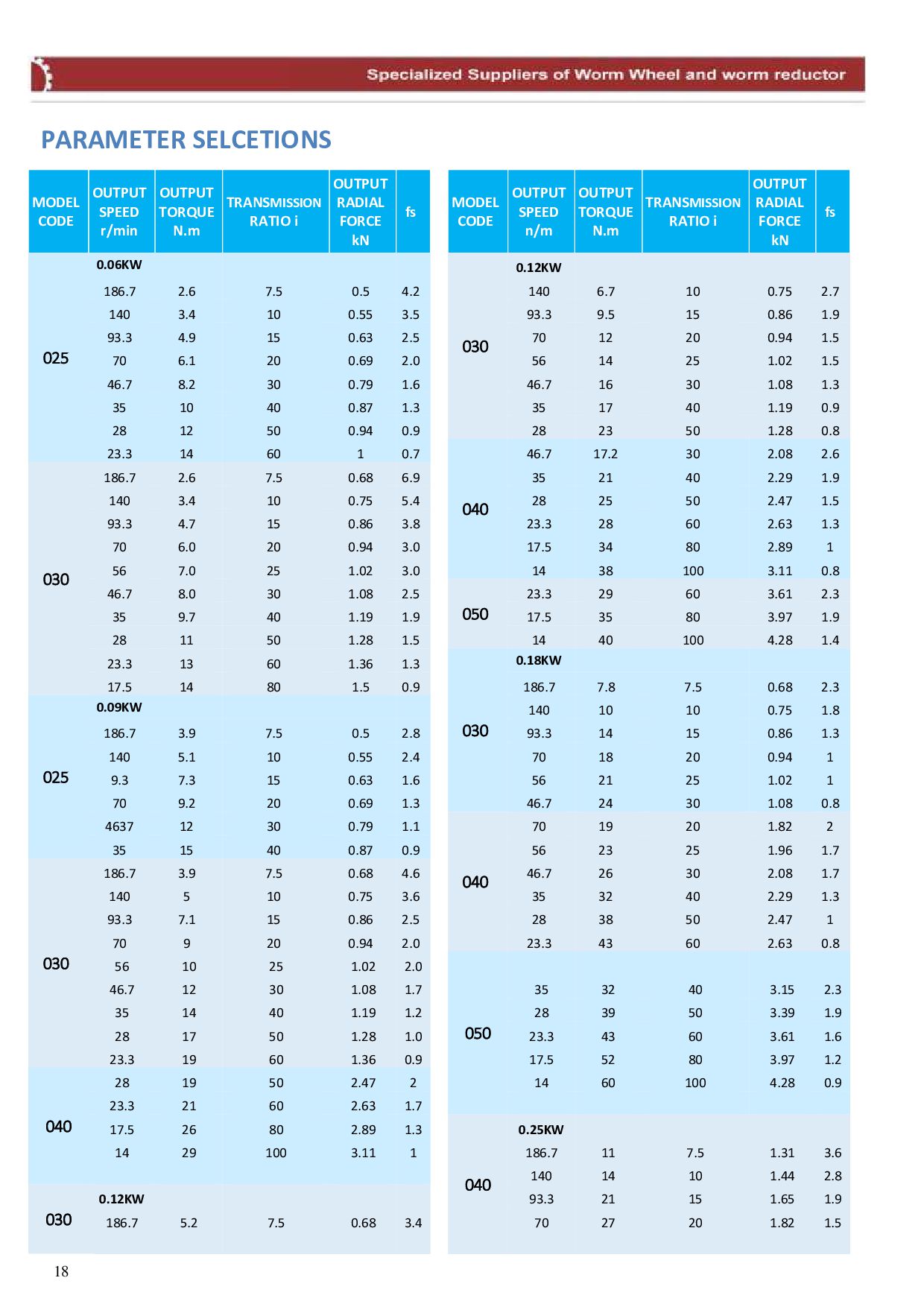
  10. PARAMETER SELCETIONS MODEL CODE OUTPUT SPEED r/min OUTPUT TORQUE N.m

    TRANSMISSION RATIO i OUTPUT RADIAL FORCE kN fs MODEL CODE OUTPUT SPEED n/m OUTPUT TORQUE N.m TRANSMISSION RATIO i OUTPUT RADIAL FORCE kN fs 025 0.06KW 030 0.12KW 186.7 2.6 7.5 0.5 4.2 140 6.7 10 0.75 2.7 140 3.4 10 0.55 3.5 93.3 9.5 15 0.86 1.9 93.3 4.9 15 0.63 2.5 70 12 20 0.94 1.5 70 6.1 20 0.69 2.0 56 14 25 1.02 1.5 46.7 8.2 30 0.79 1.6 46.7 16 30 1.08 1.3 35 10 40 0.87 1.3 35 17 40 1.19 0.9 28 12 50 0.94 0.9 28 23 50 1.28 0.8 23.3 14 60 1 0.7 040 46.7 17.2 30 2.08 2.6 030 186.7 2.6 7.5 0.68 6.9 35 21 40 2.29 1.9 140 3.4 10 0.75 5.4 28 25 50 2.47 1.5 93.3 4.7 15 0.86 3.8 23.3 28 60 2.63 1.3 70 6.0 20 0.94 3.0 17.5 34 80 2.89 1 56 7.0 25 1.02 3.0 14 38 100 3.11 0.8 46.7 8.0 30 1.08 2.5 050 23.3 29 60 3.61 2.3 35 9.7 40 1.19 1.9 17.5 35 80 3.97 1.9 28 11 50 1.28 1.5 14 40 100 4.28 1.4 23.3 13 60 1.36 1.3 030 0.18KW 17.5 14 80 1.5 0.9 186.7 7.8 7.5 0.68 2.3 025 0.09KW 140 10 10 0.75 1.8 186.7 3.9 7.5 0.5 2.8 93.3 14 15 0.86 1.3 140 5.1 10 0.55 2.4 70 18 20 0.94 1 9.3 7.3 15 0.63 1.6 56 21 25 1.02 1 70 9.2 20 0.69 1.3 46.7 24 30 1.08 0.8 4637 12 30 0.79 1.1 040 70 19 20 1.82 2 35 15 40 0.87 0.9 56 23 25 1.96 1.7 030 186.7 3.9 7.5 0.68 4.6 46.7 26 30 2.08 1.7 140 5 10 0.75 3.6 35 32 40 2.29 1.3 93.3 7.1 15 0.86 2.5 28 38 50 2.47 1 70 9 20 0.94 2.0 23.3 43 60 2.63 0.8 56 10 25 1.02 2.0 050 46.7 12 30 1.08 1.7 35 32 40 3.15 2.3 35 14 40 1.19 1.2 28 39 50 3.39 1.9 28 17 50 1.28 1.0 23.3 43 60 3.61 1.6 23.3 19 60 1.36 0.9 17.5 52 80 3.97 1.2 040 28 19 50 2.47 2 14 60 100 4.28 0.9 23.3 21 60 2.63 1.7 17.5 26 80 2.89 1.3 040 0.25KW 14 29 100 3.11 1 186.7 11 7.5 1.31 3.6 140 14 10 1.44 2.8 030 0.12KW 93.3 21 15 1.65 1.9 186.7 5.2 7.5 0.68 3.4 70 27 20 1.82 1.5 18
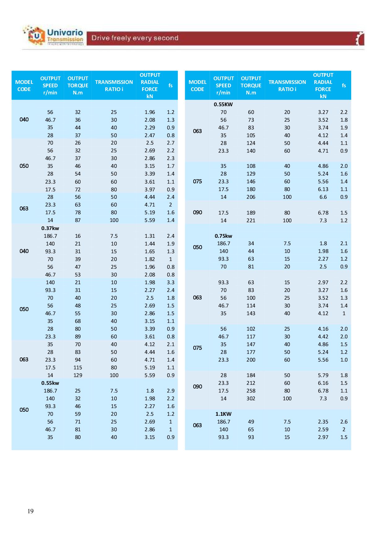
  11. MODEL CODE OUTPUT SPEED r/min OUTPUT TORQUE N.m TRANSMISSION RATIO

    i OUTPUT RADIAL FORCE kN fs MODEL CODE OUTPUT SPEED r/min OUTPUT TORQUE N.m TRANSMISSION RATIO i OUTPUT RADIAL FORCE kN fs 040 063 0.55KW 56 32 25 1.96 1.2 70 60 20 3.27 2.2 46.7 36 30 2.08 1.3 56 73 25 3.52 1.8 35 44 40 2.29 0.9 46.7 83 30 3.74 1.9 28 37 50 2.47 0.8 35 105 40 4.12 1.4 050 70 26 20 2.5 2.7 28 124 50 4.44 1.1 56 32 25 2.69 2.2 23.3 140 60 4.71 0.9 46.7 37 30 2.86 2.3 35 46 40 3.15 1.7 075 35 108 40 4.86 2.0 28 54 50 3.39 1.4 28 129 50 5.24 1.6 23.3 60 60 3.61 1.1 23.3 146 60 5.56 1.4 17.5 72 80 3.97 0.9 17.5 180 80 6.13 1.1 063 28 56 50 4.44 2.4 14 206 100 6.6 0.9 23.3 63 60 4.71 2 090 17.5 78 80 5.19 1.6 17.5 189 80 6.78 1.5 14 87 100 5.59 1.4 14 221 100 7.3 1.2 040 0.37kw 050 186.7 16 7.5 1.31 2.4 0.75kw 140 21 10 1.44 1.9 186.7 34 7.5 1.8 2.1 93.3 31 15 1.65 1.3 140 44 10 1.98 1.6 70 39 20 1.82 1 93.3 63 15 2.27 1.2 56 47 25 1.96 0.8 70 81 20 2.5 0.9 46.7 53 30 2.08 0.8 063 050 140 21 10 1.98 3.3 93.3 63 15 2.97 2.2 93.3 31 15 2.27 2.4 70 83 20 3.27 1.6 70 40 20 2.5 1.8 56 100 25 3.52 1.3 56 48 25 2.69 1.5 46.7 114 30 3.74 1.4 46.7 55 30 2.86 1.5 35 143 40 4.12 1 35 68 40 3.15 1.1 28 80 50 3.39 0.9 075 56 102 25 4.16 2.0 23.3 89 60 3.61 0.8 46.7 117 30 4.42 2.0 063 35 70 40 4.12 2.1 35 147 40 4.86 1.5 28 83 50 4.44 1.6 28 177 50 5.24 1.2 23.3 94 60 4.71 1.4 23.3 200 60 5.56 1.0 17.5 115 80 5.19 1.1 14 129 100 5.59 0.9 090 28 184 50 5.79 1.8 050 0.55kw 23.3 212 60 6.16 1.5 186.7 25 7.5 1.8 2.9 17.5 258 80 6.78 1.1 140 32 10 1.98 2.2 14 302 100 7.3 0.9 93.3 46 15 2.27 1.6 70 59 20 2.5 1.2 063 1.1KW 56 71 25 2.69 1 186.7 49 7.5 2.35 2.6 46.7 81 30 2.86 1 140 65 10 2.59 2 35 80 40 3.15 0.9 93.3 93 15 2.97 1.5 19
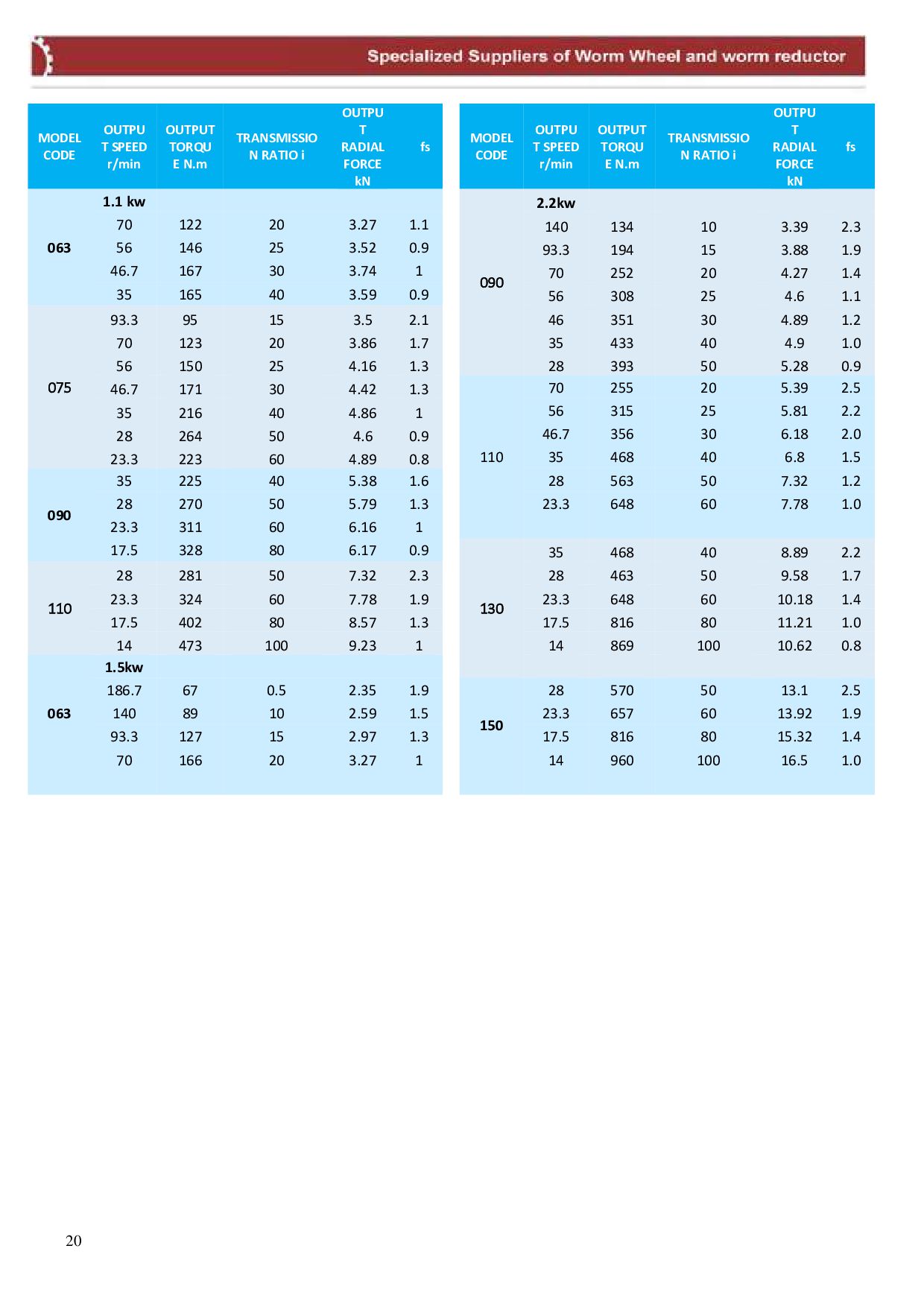
  12. MODEL CODE OUTPU T SPEED r/min OUTPUT TORQU E N.m

    TRANSMISSIO N RATIO i OUTPU T RADIAL FORCE kN fs MODEL CODE OUTPU T SPEED r/min OUTPUT TORQU E N.m TRANSMISSIO N RATIO i OUTPU T RADIAL FORCE kN fs 063 1.1 kw 090 2.2kw 70 122 20 3.27 1.1 140 134 10 3.39 2.3 56 146 25 3.52 0.9 93.3 194 15 3.88 1.9 46.7 167 30 3.74 1 70 252 20 4.27 1.4 35 165 40 3.59 0.9 56 308 25 4.6 1.1 075 93.3 95 15 3.5 2.1 46 351 30 4.89 1.2 70 123 20 3.86 1.7 35 433 40 4.9 1.0 56 150 25 4.16 1.3 28 393 50 5.28 0.9 46.7 171 30 4.42 1.3 110 70 255 20 5.39 2.5 35 216 40 4.86 1 56 315 25 5.81 2.2 28 264 50 4.6 0.9 46.7 356 30 6.18 2.0 23.3 223 60 4.89 0.8 35 468 40 6.8 1.5 090 35 225 40 5.38 1.6 28 563 50 7.32 1.2 28 270 50 5.79 1.3 23.3 648 60 7.78 1.0 23.3 311 60 6.16 1 17.5 328 80 6.17 0.9 130 35 468 40 8.89 2.2 110 28 281 50 7.32 2.3 28 463 50 9.58 1.7 23.3 324 60 7.78 1.9 23.3 648 60 10.18 1.4 17.5 402 80 8.57 1.3 17.5 816 80 11.21 1.0 14 473 100 9.23 1 14 869 100 10.62 0.8 063 1.5kw 186.7 67 0.5 2.35 1.9 150 28 570 50 13.1 2.5 140 89 10 2.59 1.5 23.3 657 60 13.92 1.9 93.3 127 15 2.97 1.3 17.5 816 80 15.32 1.4 70 166 20 3.27 1 14 960 100 16.5 1.0 20
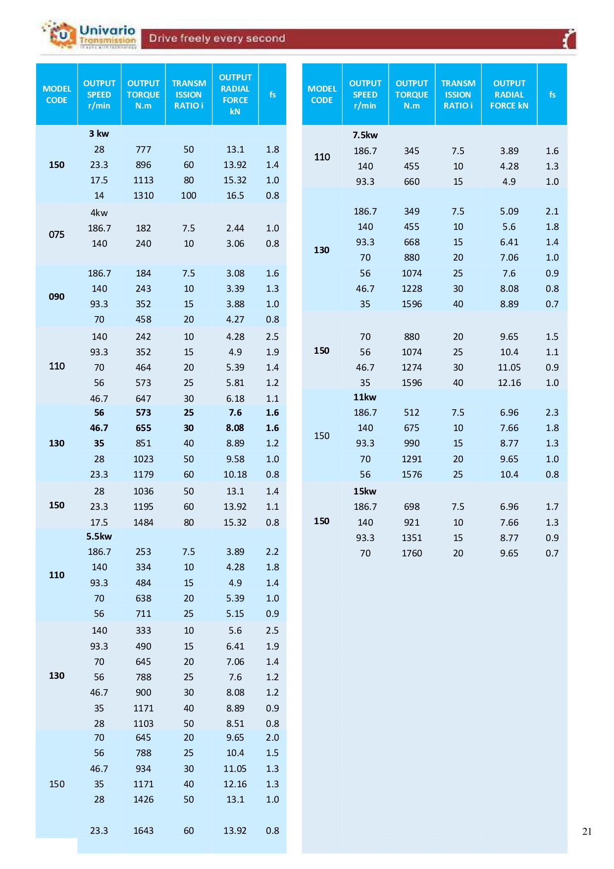
  13. MODEL CODE OUTPUT SPEED r/min OUTPUT TORQUE N.m TRANSM ISSION

    RATIO i OUTPUT RADIAL FORCE kN fs MODEL CODE OUTPUT SPEED r/min OUTPUT TORQUE N.m TRANSM ISSION RATIO i OUTPUT RADIAL FORCE kN fs 150 3 kw 110 7.5kw 28 777 50 13.1 1.8 186.7 345 7.5 3.89 1.6 23.3 896 60 13.92 1.4 140 455 10 4.28 1.3 17.5 1113 80 15.32 1.0 93.3 660 15 4.9 1.0 14 1310 100 16.5 0.8 130 075 4kw 186.7 349 7.5 5.09 2.1 186.7 182 7.5 2.44 1.0 140 455 10 5.6 1.8 140 240 10 3.06 0.8 93.3 668 15 6.41 1.4 70 880 20 7.06 1.0 090 186.7 184 7.5 3.08 1.6 56 1074 25 7.6 0.9 140 243 10 3.39 1.3 46.7 1228 30 8.08 0.8 93.3 352 15 3.88 1.0 35 1596 40 8.89 0.7 70 458 20 4.27 0.8 150 110 140 242 10 4.28 2.5 70 880 20 9.65 1.5 93.3 352 15 4.9 1.9 56 1074 25 10.4 1.1 70 464 20 5.39 1.4 46.7 1274 30 11.05 0.9 56 573 25 5.81 1.2 35 1596 40 12.16 1.0 46.7 647 30 6.18 1.1 150 11kw 130 56 573 25 7.6 1.6 186.7 512 7.5 6.96 2.3 46.7 655 30 8.08 1.6 140 675 10 7.66 1.8 35 851 40 8.89 1.2 93.3 990 15 8.77 1.3 28 1023 50 9.58 1.0 70 1291 20 9.65 1.0 23.3 1179 60 10.18 0.8 56 1576 25 10.4 0.8 150 28 1036 50 13.1 1.4 150 15kw 23.3 1195 60 13.92 1.1 186.7 698 7.5 6.96 1.7 17.5 1484 80 15.32 0.8 140 921 10 7.66 1.3 110 5.5kw 93.3 1351 15 8.77 0.9 186.7 253 7.5 3.89 2.2 70 1760 20 9.65 0.7 140 334 10 4.28 1.8 93.3 484 15 4.9 1.4 70 638 20 5.39 1.0 56 711 25 5.15 0.9 130 140 333 10 5.6 2.5 93.3 490 15 6.41 1.9 70 645 20 7.06 1.4 56 788 25 7.6 1.2 46.7 900 30 8.08 1.2 35 1171 40 8.89 0.9 28 1103 50 8.51 0.8 150 70 645 20 9.65 2.0 56 788 25 10.4 1.5 46.7 934 30 11.05 1.3 35 1171 40 12.16 1.3 28 1426 50 13.1 1.0 23.3 1643 60 13.92 0.8 21
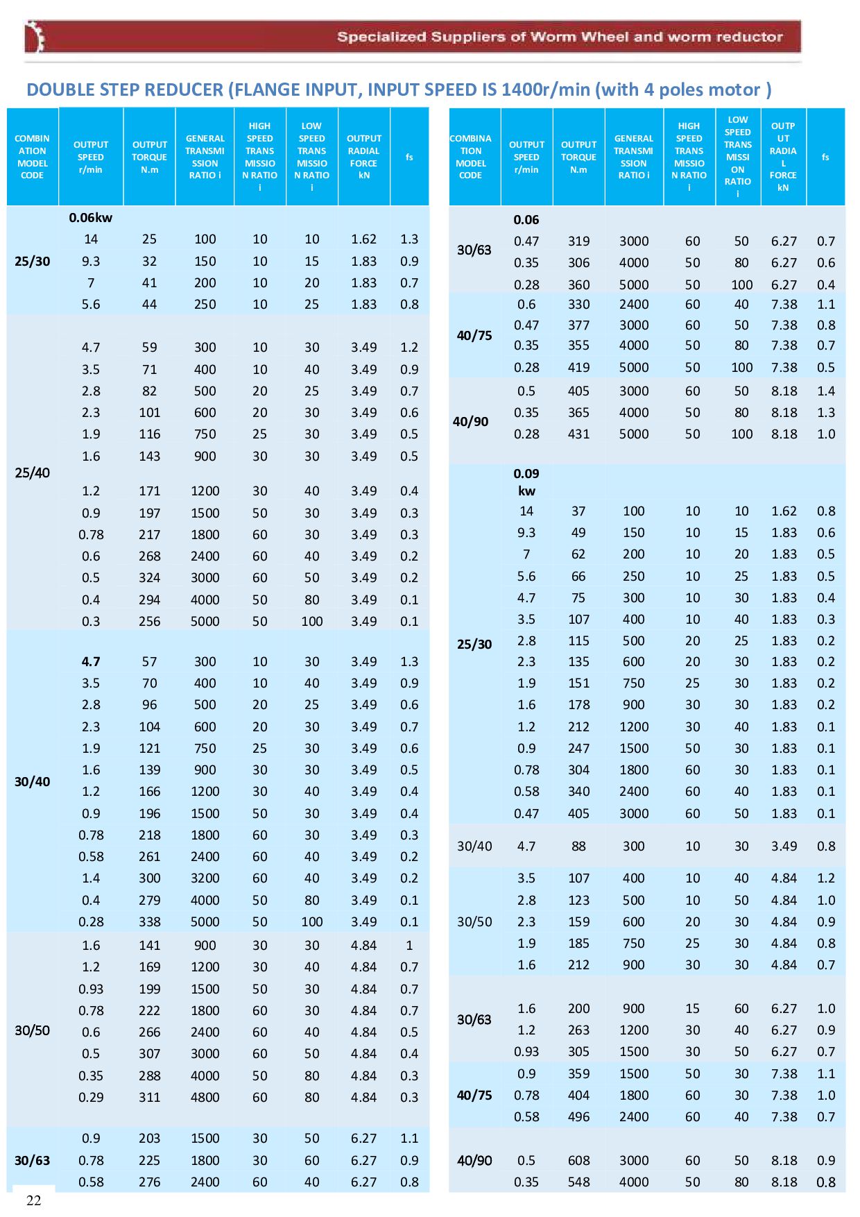
  14. DOUBLE STEP REDUCER (FLANGE INPUT, INPUT SPEED IS 1400r/min (with

    4 poles motor ) COMBIN ATION MODEL CODE OUTPUT SPEED r/min OUTPUT TORQUE N.m GENERAL TRANSMI SSION RATIO i HIGH SPEED TRANS MISSIO N RATIO i LOW SPEED TRANS MISSIO N RATIO i OUTPUT RADIAL FORCE kN fs COMBINA TION MODEL CODE OUTPUT SPEED r/min OUTPUT TORQUE N.m GENERAL TRANSMI SSION RATIO i HIGH SPEED TRANS MISSIO N RATIO i LOW SPEED TRANS MISSI ON RATIO i OUTP UT RADIA L FORCE kN fs 25/30 0.06kw 30/63 0.06 14 25 100 10 10 1.62 1.3 0.47 319 3000 60 50 6.27 0.7 9.3 32 150 10 15 1.83 0.9 0.35 306 4000 50 80 6.27 0.6 7 41 200 10 20 1.83 0.7 0.28 360 5000 50 100 6.27 0.4 5.6 44 250 10 25 1.83 0.8 40/75 0.6 330 2400 60 40 7.38 1.1 25/40 0.47 377 3000 60 50 7.38 0.8 4.7 59 300 10 30 3.49 1.2 0.35 355 4000 50 80 7.38 0.7 3.5 71 400 10 40 3.49 0.9 0.28 419 5000 50 100 7.38 0.5 2.8 82 500 20 25 3.49 0.7 40/90 0.5 405 3000 60 50 8.18 1.4 2.3 101 600 20 30 3.49 0.6 0.35 365 4000 50 80 8.18 1.3 1.9 116 750 25 30 3.49 0.5 0.28 431 5000 50 100 8.18 1.0 1.6 143 900 30 30 3.49 0.5 1.2 171 1200 30 40 3.49 0.4 25/30 0.09 kw 0.9 197 1500 50 30 3.49 0.3 14 37 100 10 10 1.62 0.8 0.78 217 1800 60 30 3.49 0.3 9.3 49 150 10 15 1.83 0.6 0.6 268 2400 60 40 3.49 0.2 7 62 200 10 20 1.83 0.5 0.5 324 3000 60 50 3.49 0.2 5.6 66 250 10 25 1.83 0.5 0.4 294 4000 50 80 3.49 0.1 4.7 75 300 10 30 1.83 0.4 0.3 256 5000 50 100 3.49 0.1 3.5 107 400 10 40 1.83 0.3 30/40 2.8 115 500 20 25 1.83 0.2 4.7 57 300 10 30 3.49 1.3 2.3 135 600 20 30 1.83 0.2 3.5 70 400 10 40 3.49 0.9 1.9 151 750 25 30 1.83 0.2 2.8 96 500 20 25 3.49 0.6 1.6 178 900 30 30 1.83 0.2 2.3 104 600 20 30 3.49 0.7 1.2 212 1200 30 40 1.83 0.1 1.9 121 750 25 30 3.49 0.6 0.9 247 1500 50 30 1.83 0.1 1.6 139 900 30 30 3.49 0.5 0.78 304 1800 60 30 1.83 0.1 1.2 166 1200 30 40 3.49 0.4 0.58 340 2400 60 40 1.83 0.1 0.9 196 1500 50 30 3.49 0.4 0.47 405 3000 60 50 1.83 0.1 0.78 218 1800 60 30 3.49 0.3 30/40 4.7 88 300 10 30 3.49 0.8 0.58 261 2400 60 40 3.49 0.2 1.4 300 3200 60 40 3.49 0.2 30/50 3.5 107 400 10 40 4.84 1.2 0.4 279 4000 50 80 3.49 0.1 2.8 123 500 10 50 4.84 1.0 0.28 338 5000 50 100 3.49 0.1 2.3 159 600 20 30 4.84 0.9 30/50 1.6 141 900 30 30 4.84 1 1.9 185 750 25 30 4.84 0.8 1.2 169 1200 30 40 4.84 0.7 1.6 212 900 30 30 4.84 0.7 0.93 199 1500 50 30 4.84 0.7 30/63 0.78 222 1800 60 30 4.84 0.7 1.6 200 900 15 60 6.27 1.0 0.6 266 2400 60 40 4.84 0.5 1.2 263 1200 30 40 6.27 0.9 0.5 307 3000 60 50 4.84 0.4 0.93 305 1500 30 50 6.27 0.7 0.35 288 4000 50 80 4.84 0.3 40/75 0.9 359 1500 50 30 7.38 1.1 0.29 311 4800 60 80 4.84 0.3 0.78 404 1800 60 30 7.38 1.0 0.58 496 2400 60 40 7.38 0.7 30/63 0.9 203 1500 30 50 6.27 1.1 40/90 0.78 225 1800 30 60 6.27 0.9 0.5 608 3000 60 50 8.18 0.9 0.58 276 2400 60 40 6.27 0.8 0.35 548 4000 50 80 8.18 0.8 22
  15. 23

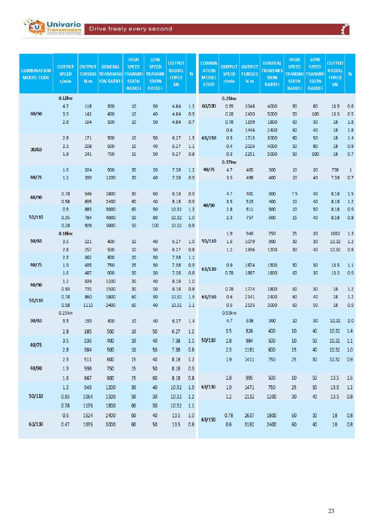
  16. COMBINATION MODEL CODE OUTPUT SPEED r/min OUTPUT TORQUE N.m GENERAL

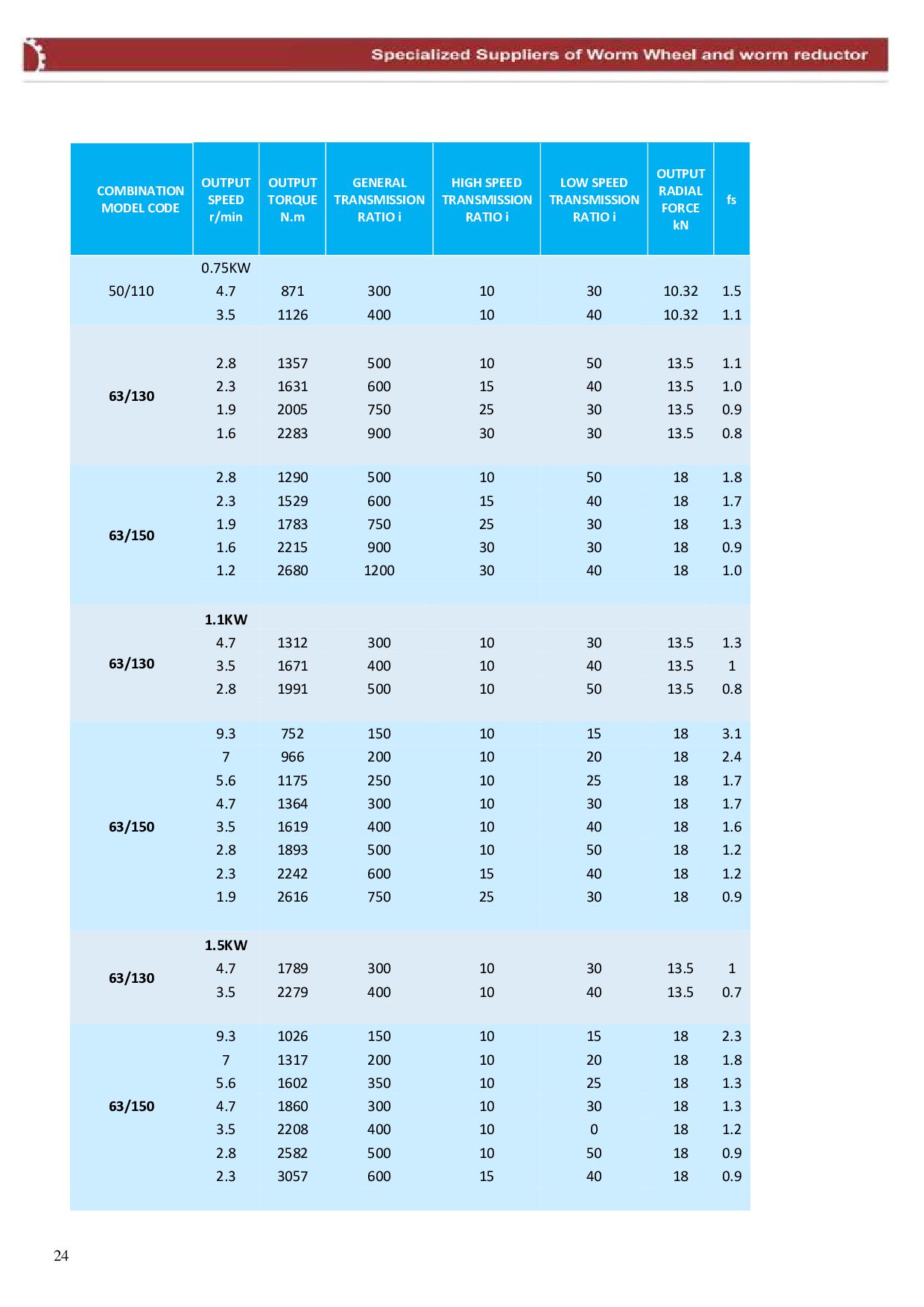
    TRANSMISSION RATIO i HIGH SPEED TRANSMISSION RATIO i LOW SPEED TRANSMISSION RATIO i OUTPUT RADIAL FORCE kN fs 50/110 0.75KW 4.7 871 300 10 30 10.32 1.5 3.5 1126 400 10 40 10.32 1.1 63/130 2.8 1357 500 10 50 13.5 1.1 2.3 1631 600 15 40 13.5 1.0 1.9 2005 750 25 30 13.5 0.9 1.6 2283 900 30 30 13.5 0.8 63/150 2.8 1290 500 10 50 18 1.8 2.3 1529 600 15 40 18 1.7 1.9 1783 750 25 30 18 1.3 1.6 2215 900 30 30 18 0.9 1.2 2680 1200 30 40 18 1.0 63/130 1.1KW 4.7 1312 300 10 30 13.5 1.3 3.5 1671 400 10 40 13.5 1 2.8 1991 500 10 50 13.5 0.8 63/150 9.3 752 150 10 15 18 3.1 7 966 200 10 20 18 2.4 5.6 1175 250 10 25 18 1.7 4.7 1364 300 10 30 18 1.7 3.5 1619 400 10 40 18 1.6 2.8 1893 500 10 50 18 1.2 2.3 2242 600 15 40 18 1.2 1.9 2616 750 25 30 18 0.9 63/130 1.5KW 4.7 1789 300 10 30 13.5 1 3.5 2279 400 10 40 13.5 0.7 63/150 9.3 1026 150 10 15 18 2.3 7 1317 200 10 20 18 1.8 5.6 1602 350 10 25 18 1.3 4.7 1860 300 10 30 18 1.3 3.5 2208 400 10 0 18 1.2 2.8 2582 500 10 50 18 0.9 2.3 3057 600 15 40 18 0.9 24
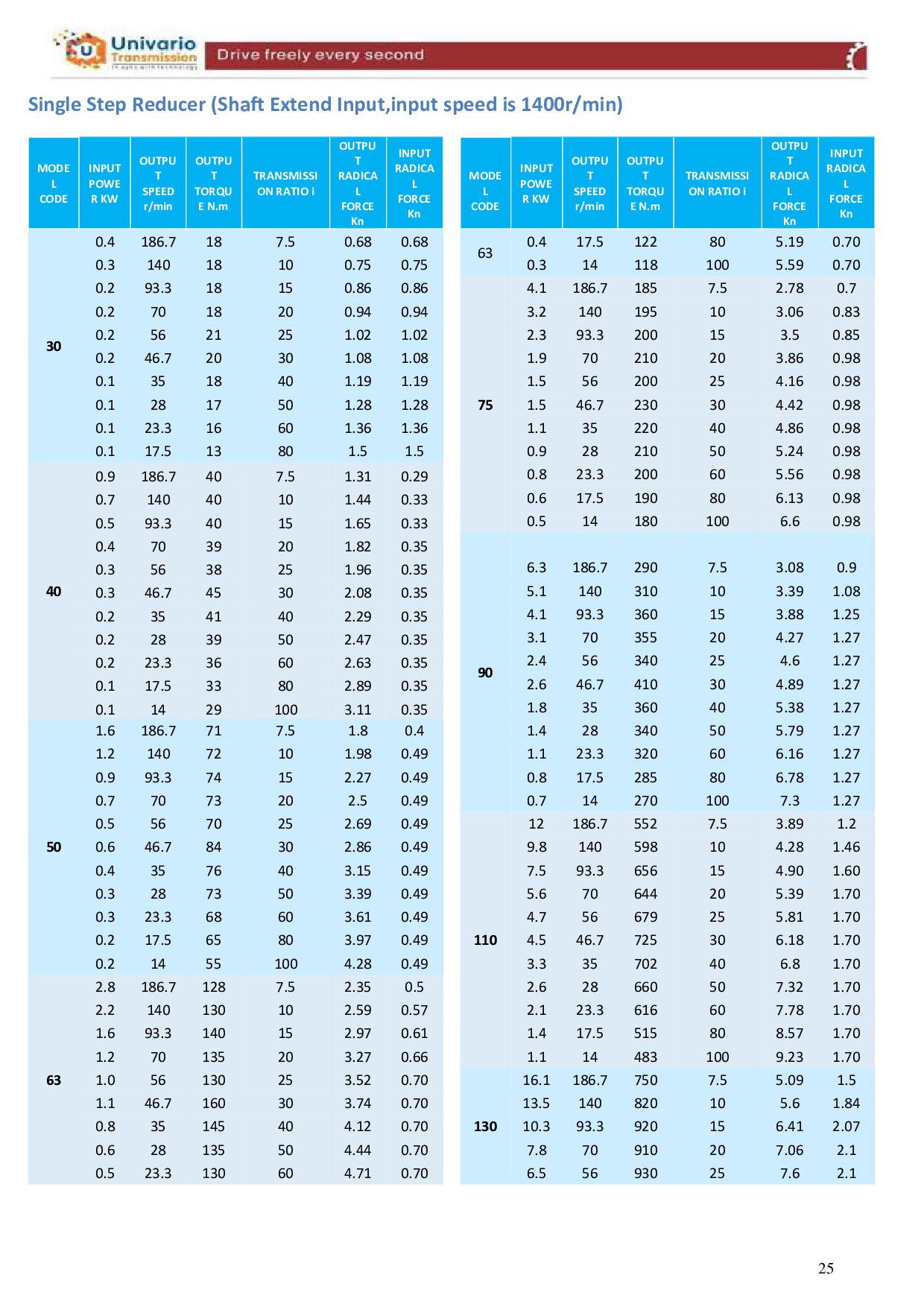
  17. Single Step Reducer (Shaft Extend Input,input speed is 1400r/min) MODE

    L CODE INPUT POWE R KW OUTPU T SPEED r/min OUTPU T TORQU E N.m TRANSMISSI ON RATIO i OUTPU T RADICA L FORCE Kn INPUT RADICA L FORCE Kn MODE L CODE INPUT POWE R KW OUTPU T SPEED r/min OUTPU T TORQU E N.m TRANSMISSI ON RATIO i OUTPU T RADICA L FORCE Kn INPUT RADICA L FORCE Kn 30 0.4 186.7 18 7.5 0.68 0.68 63 0.4 17.5 122 80 5.19 0.70 0.3 140 18 10 0.75 0.75 0.3 14 118 100 5.59 0.70 0.2 93.3 18 15 0.86 0.86 75 4.1 186.7 185 7.5 2.78 0.7 0.2 70 18 20 0.94 0.94 3.2 140 195 10 3.06 0.83 0.2 56 21 25 1.02 1.02 2.3 93.3 200 15 3.5 0.85 0.2 46.7 20 30 1.08 1.08 1.9 70 210 20 3.86 0.98 0.1 35 18 40 1.19 1.19 1.5 56 200 25 4.16 0.98 0.1 28 17 50 1.28 1.28 1.5 46.7 230 30 4.42 0.98 0.1 23.3 16 60 1.36 1.36 1.1 35 220 40 4.86 0.98 0.1 17.5 13 80 1.5 1.5 0.9 28 210 50 5.24 0.98 40 0.9 186.7 40 7.5 1.31 0.29 0.8 23.3 200 60 5.56 0.98 0.7 140 40 10 1.44 0.33 0.6 17.5 190 80 6.13 0.98 0.5 93.3 40 15 1.65 0.33 0.5 14 180 100 6.6 0.98 0.4 70 39 20 1.82 0.35 90 0.3 56 38 25 1.96 0.35 6.3 186.7 290 7.5 3.08 0.9 0.3 46.7 45 30 2.08 0.35 5.1 140 310 10 3.39 1.08 0.2 35 41 40 2.29 0.35 4.1 93.3 360 15 3.88 1.25 0.2 28 39 50 2.47 0.35 3.1 70 355 20 4.27 1.27 0.2 23.3 36 60 2.63 0.35 2.4 56 340 25 4.6 1.27 0.1 17.5 33 80 2.89 0.35 2.6 46.7 410 30 4.89 1.27 0.1 14 29 100 3.11 0.35 1.8 35 360 40 5.38 1.27 50 1.6 186.7 71 7.5 1.8 0.4 1.4 28 340 50 5.79 1.27 1.2 140 72 10 1.98 0.49 1.1 23.3 320 60 6.16 1.27 0.9 93.3 74 15 2.27 0.49 0.8 17.5 285 80 6.78 1.27 0.7 70 73 20 2.5 0.49 0.7 14 270 100 7.3 1.27 0.5 56 70 25 2.69 0.49 110 12 186.7 552 7.5 3.89 1.2 0.6 46.7 84 30 2.86 0.49 9.8 140 598 10 4.28 1.46 0.4 35 76 40 3.15 0.49 7.5 93.3 656 15 4.90 1.60 0.3 28 73 50 3.39 0.49 5.6 70 644 20 5.39 1.70 0.3 23.3 68 60 3.61 0.49 4.7 56 679 25 5.81 1.70 0.2 17.5 65 80 3.97 0.49 4.5 46.7 725 30 6.18 1.70 0.2 14 55 100 4.28 0.49 3.3 35 702 40 6.8 1.70 63 2.8 186.7 128 7.5 2.35 0.5 2.6 28 660 50 7.32 1.70 2.2 140 130 10 2.59 0.57 2.1 23.3 616 60 7.78 1.70 1.6 93.3 140 15 2.97 0.61 1.4 17.5 515 80 8.57 1.70 1.2 70 135 20 3.27 0.66 1.1 14 483 100 9.23 1.70 1.0 56 130 25 3.52 0.70 130 16.1 186.7 750 7.5 5.09 1.5 1.1 46.7 160 30 3.74 0.70 13.5 140 820 10 5.6 1.84 0.8 35 145 40 4.12 0.70 10.3 93.3 920 15 6.41 2.07 0.6 28 135 50 4.44 0.70 7.8 70 910 20 7.06 2.1 0.5 23.3 130 60 4.71 0.70 6.5 56 930 25 7.6 2.1 25
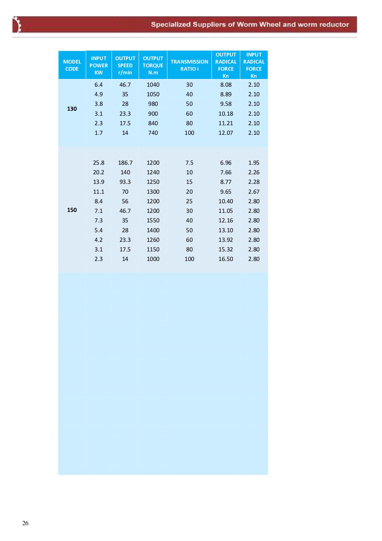
  18. MODEL CODE INPUT POWER KW OUTPUT SPEED r/min OUTPUT TORQUE

    N.m TRANSMISSION RATIO i OUTPUT RADICAL FORCE Kn INPUT RADICAL FORCE Kn 130 6.4 46.7 1040 30 8.08 2.10 4.9 35 1050 40 8.89 2.10 3.8 28 980 50 9.58 2.10 3.1 23.3 900 60 10.18 2.10 2.3 17.5 840 80 11.21 2.10 1.7 14 740 100 12.07 2.10 150 25.8 186.7 1200 7.5 6.96 1.95 20.2 140 1240 10 7.66 2.26 13.9 93.3 1250 15 8.77 2.28 11.1 70 1300 20 9.65 2.67 8.4 56 1200 25 10.40 2.80 7.1 46.7 1200 30 11.05 2.80 7.3 35 1550 40 12.16 2.80 5.4 28 1400 50 13.10 2.80 4.2 23.3 1260 60 13.92 2.80 3.1 17.5 1150 80 15.32 2.80 2.3 14 1000 100 16.50 2.80 26
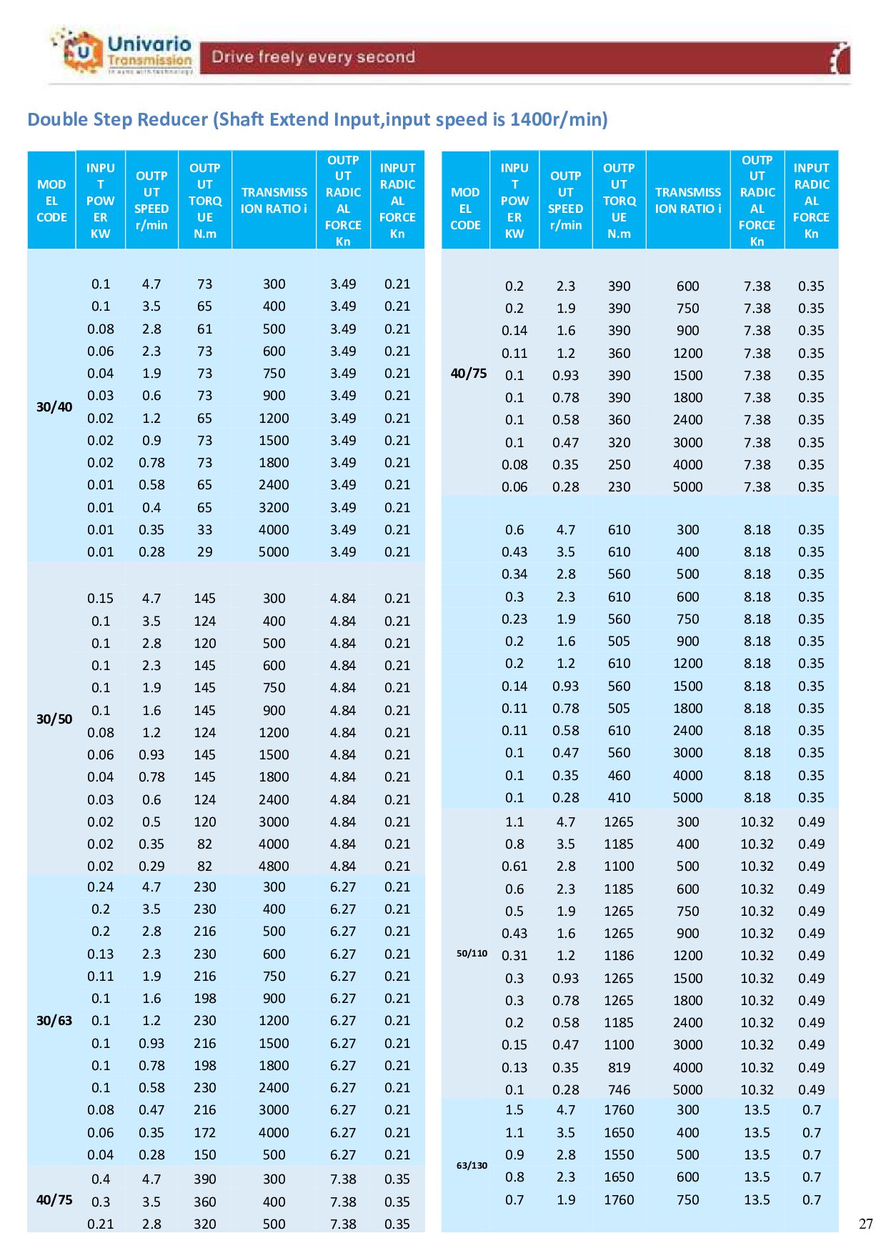
  19. Double Step Reducer (Shaft Extend Input,input speed is 1400r/min) MOD

    EL CODE INPU T POW ER KW OUTP UT SPEED r/min OUTP UT TORQ UE N.m TRANSMISS ION RATIO i OUTP UT RADIC AL FORCE Kn INPUT RADIC AL FORCE Kn MOD EL CODE INPU T POW ER KW OUTP UT SPEED r/min OUTP UT TORQ UE N.m TRANSMISS ION RATIO i OUTP UT RADIC AL FORCE Kn INPUT RADIC AL FORCE Kn 30/40 40/75 0.1 4.7 73 300 3.49 0.21 0.2 2.3 390 600 7.38 0.35 0.1 3.5 65 400 3.49 0.21 0.2 1.9 390 750 7.38 0.35 0.08 2.8 61 500 3.49 0.21 0.14 1.6 390 900 7.38 0.35 0.06 2.3 73 600 3.49 0.21 0.11 1.2 360 1200 7.38 0.35 0.04 1.9 73 750 3.49 0.21 0.1 0.93 390 1500 7.38 0.35 0.03 0.6 73 900 3.49 0.21 0.1 0.78 390 1800 7.38 0.35 0.02 1.2 65 1200 3.49 0.21 0.1 0.58 360 2400 7.38 0.35 0.02 0.9 73 1500 3.49 0.21 0.1 0.47 320 3000 7.38 0.35 0.02 0.78 73 1800 3.49 0.21 0.08 0.35 250 4000 7.38 0.35 0.01 0.58 65 2400 3.49 0.21 0.06 0.28 230 5000 7.38 0.35 0.01 0.4 65 3200 3.49 0.21 0.01 0.35 33 4000 3.49 0.21 0.6 4.7 610 300 8.18 0.35 0.01 0.28 29 5000 3.49 0.21 0.43 3.5 610 400 8.18 0.35 30/50 0.34 2.8 560 500 8.18 0.35 0.15 4.7 145 300 4.84 0.21 0.3 2.3 610 600 8.18 0.35 0.1 3.5 124 400 4.84 0.21 0.23 1.9 560 750 8.18 0.35 0.1 2.8 120 500 4.84 0.21 0.2 1.6 505 900 8.18 0.35 0.1 2.3 145 600 4.84 0.21 0.2 1.2 610 1200 8.18 0.35 0.1 1.9 145 750 4.84 0.21 0.14 0.93 560 1500 8.18 0.35 0.1 1.6 145 900 4.84 0.21 0.11 0.78 505 1800 8.18 0.35 0.08 1.2 124 1200 4.84 0.21 0.11 0.58 610 2400 8.18 0.35 0.06 0.93 145 1500 4.84 0.21 0.1 0.47 560 3000 8.18 0.35 0.04 0.78 145 1800 4.84 0.21 0.1 0.35 460 4000 8.18 0.35 0.03 0.6 124 2400 4.84 0.21 0.1 0.28 410 5000 8.18 0.35 0.02 0.5 120 3000 4.84 0.21 50/110 1.1 4.7 1265 300 10.32 0.49 0.02 0.35 82 4000 4.84 0.21 0.8 3.5 1185 400 10.32 0.49 0.02 0.29 82 4800 4.84 0.21 0.61 2.8 1100 500 10.32 0.49 30/63 0.24 4.7 230 300 6.27 0.21 0.6 2.3 1185 600 10.32 0.49 0.2 3.5 230 400 6.27 0.21 0.5 1.9 1265 750 10.32 0.49 0.2 2.8 216 500 6.27 0.21 0.43 1.6 1265 900 10.32 0.49 0.13 2.3 230 600 6.27 0.21 0.31 1.2 1186 1200 10.32 0.49 0.11 1.9 216 750 6.27 0.21 0.3 0.93 1265 1500 10.32 0.49 0.1 1.6 198 900 6.27 0.21 0.3 0.78 1265 1800 10.32 0.49 0.1 1.2 230 1200 6.27 0.21 0.2 0.58 1185 2400 10.32 0.49 0.1 0.93 216 1500 6.27 0.21 0.15 0.47 1100 3000 10.32 0.49 0.1 0.78 198 1800 6.27 0.21 0.13 0.35 819 4000 10.32 0.49 0.1 0.58 230 2400 6.27 0.21 0.1 0.28 746 5000 10.32 0.49 0.08 0.47 216 3000 6.27 0.21 63/130 1.5 4.7 1760 300 13.5 0.7 0.06 0.35 172 4000 6.27 0.21 1.1 3.5 1650 400 13.5 0.7 0.04 0.28 150 500 6.27 0.21 0.9 2.8 1550 500 13.5 0.7 40/75 0.4 4.7 390 300 7.38 0.35 0.8 2.3 1650 600 13.5 0.7 0.3 3.5 360 400 7.38 0.35 0.7 1.9 1760 750 13.5 0.7 0.21 2.8 320 500 7.38 0.35 27
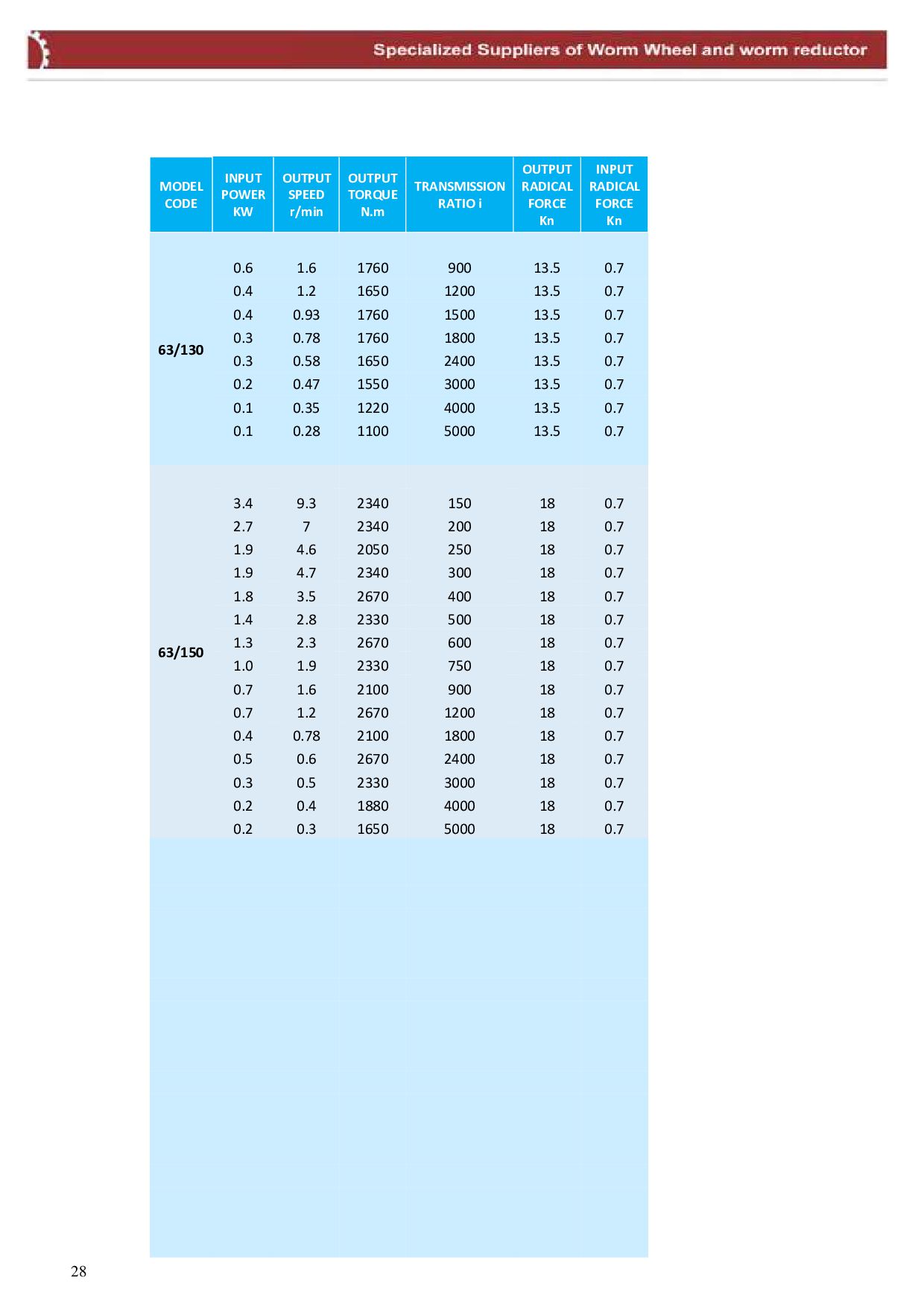
  20. MODEL CODE INPUT POWER KW OUTPUT SPEED r/min OUTPUT TORQUE

    N.m TRANSMISSION RATIO i OUTPUT RADICAL FORCE Kn INPUT RADICAL FORCE Kn 63/130 0.6 1.6 1760 900 13.5 0.7 0.4 1.2 1650 1200 13.5 0.7 0.4 0.93 1760 1500 13.5 0.7 0.3 0.78 1760 1800 13.5 0.7 0.3 0.58 1650 2400 13.5 0.7 0.2 0.47 1550 3000 13.5 0.7 0.1 0.35 1220 4000 13.5 0.7 0.1 0.28 1100 5000 13.5 0.7 63/150 3.4 9.3 2340 150 18 0.7 2.7 7 2340 200 18 0.7 1.9 4.6 2050 250 18 0.7 1.9 4.7 2340 300 18 0.7 1.8 3.5 2670 400 18 0.7 1.4 2.8 2330 500 18 0.7 1.3 2.3 2670 600 18 0.7 1.0 1.9 2330 750 18 0.7 0.7 1.6 2100 900 18 0.7 0.7 1.2 2670 1200 18 0.7 0.4 0.78 2100 1800 18 0.7 0.5 0.6 2670 2400 18 0.7 0.3 0.5 2330 3000 18 0.7 0.2 0.4 1880 4000 18 0.7 0.2 0.3 1650 5000 18 0.7 28
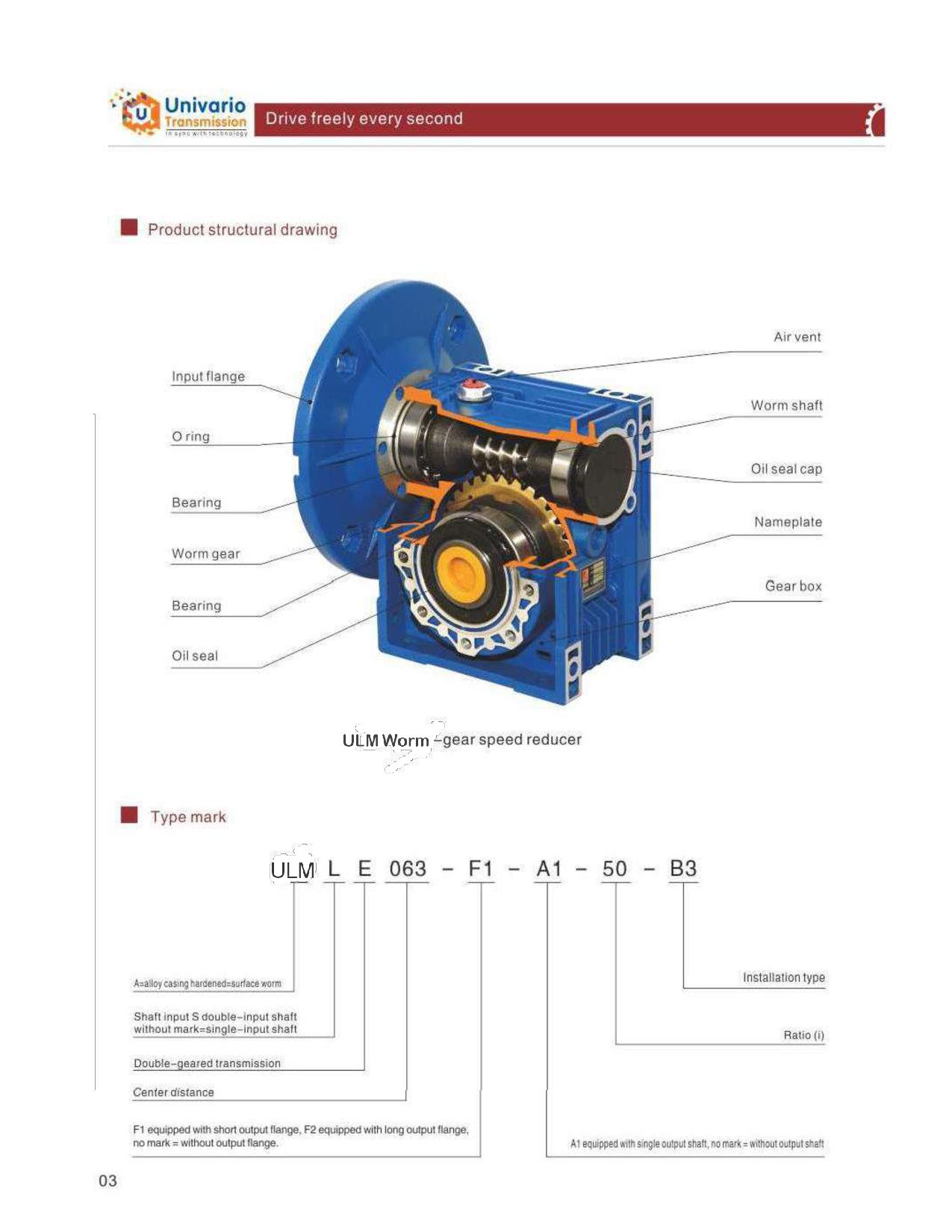
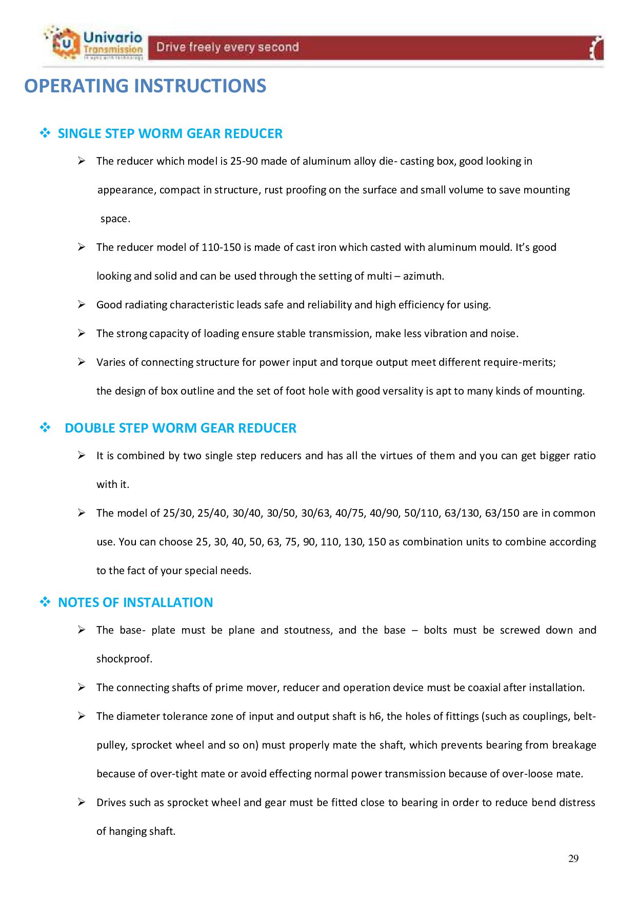
  21. OPERATING INSTRUCTIONS  SINGLE STEP WORM GEAR REDUCER  The

    reducer which model is 25-90 made of aluminum alloy die- casting box, good looking in appearance, compact in structure, rust proofing on the surface and small volume to save mounting space.  The reducer model of 110-150 is made of cast iron which casted with aluminum mould. It’s good looking and solid and can be used through the setting of multi – azimuth.  Good radiating characteristic leads safe and reliability and high efficiency for using.  The strong capacity of loading ensure stable transmission, make less vibration and noise.  Varies of connecting structure for power input and torque output meet different require-merits; the design of box outline and the set of foot hole with good versality is apt to many kinds of mounting.  DOUBLE STEP WORM GEAR REDUCER  It is combined by two single step reducers and has all the virtues of them and you can get bigger ratio with it.  The model of 25/30, 25/40, 30/40, 30/50, 30/63, 40/75, 40/90, 50/110, 63/130, 63/150 are in common use. You can choose 25, 30, 40, 50, 63, 75, 90, 110, 130, 150 as combination units to combine according to the fact of your special needs.  NOTES OF INSTALLATION  The base- plate must be plane and stoutness, and the base – bolts must be screwed down and shockproof.  The connecting shafts of prime mover, reducer and operation device must be coaxial after installation.  The diameter tolerance zone of input and output shaft is h6, the holes of fittings (such as couplings, belt- pulley, sprocket wheel and so on) must properly mate the shaft, which prevents bearing from breakage because of over-tight mate or avoid effecting normal power transmission because of over-loose mate.  Drives such as sprocket wheel and gear must be fitted close to bearing in order to reduce bend distress of hanging shaft. 29
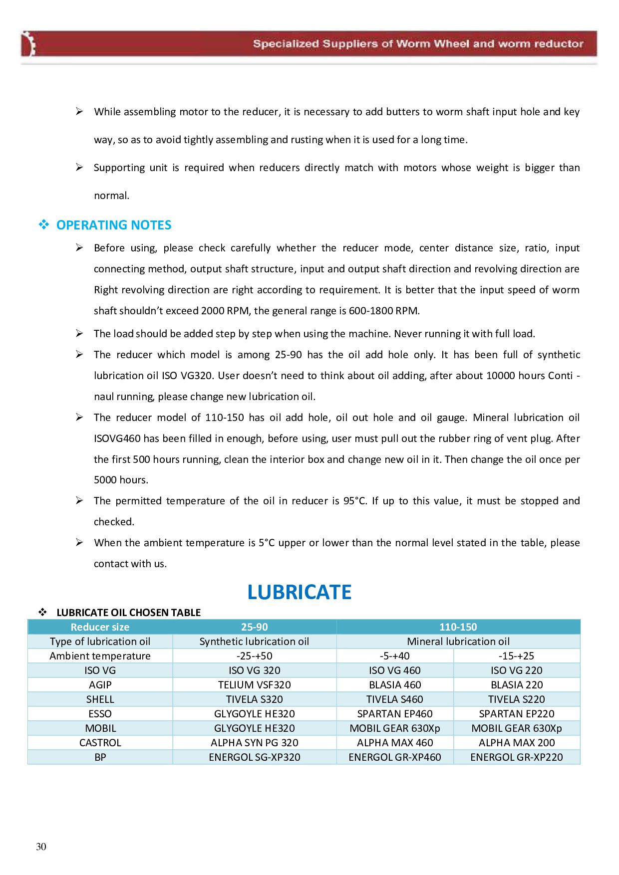
  22.  While assembling motor to the reducer, it is necessary

    to add butters to worm shaft input hole and key way, so as to avoid tightly assembling and rusting when it is used for a long time.  Supporting unit is required when reducers directly match with motors whose weight is bigger than normal.  OPERATING NOTES  Before using, please check carefully whether the reducer mode, center distance size, ratio, input connecting method, output shaft structure, input and output shaft direction and revolving direction are Right revolving direction are right according to requirement. It is better that the input speed of worm shaft shouldn’t exceed 2000 RPM, the general range is 600-1800 RPM.  The load should be added step by step when using the machine. Never running it with full load.  The reducer which model is among 25-90 has the oil add hole only. It has been full of synthetic lubrication oil ISO VG320. User doesn’t need to think about oil adding, after about 10000 hours Conti - naul running, please change new lubrication oil.  The reducer model of 110-150 has oil add hole, oil out hole and oil gauge. Mineral lubrication oil ISOVG460 has been filled in enough, before using, user must pull out the rubber ring of vent plug. After the first 500 hours running, clean the interior box and change new oil in it. Then change the oil once per 5000 hours.  The permitted temperature of the oil in reducer is 95°C. If up to this value, it must be stopped and checked.  When the ambient temperature is 5°C upper or lower than the normal level stated in the table, please contact with us. LUBRICATE  LUBRICATE OIL CHOSEN TABLE Reducer size 25-90 110-150 Type of lubrication oil Synthetic lubrication oil Mineral lubrication oil Ambient temperature -25-+50 -5-+40 -15-+25 ISO VG ISO VG 320 ISO VG 460 ISO VG 220 AGIP TELIUM VSF320 BLASIA 460 BLASIA 220 SHELL TIVELA S320 TIVELA S460 TIVELA S220 ESSO GLYGOYLE HE320 SPARTAN EP460 SPARTAN EP220 MOBIL GLYGOYLE HE320 MOBIL GEAR 630Xp MOBIL GEAR 630Xp CASTROL ALPHA SYN PG 320 ALPHA MAX 460 ALPHA MAX 200 BP ENERGOL SG-XP320 ENERGOL GR-XP460 ENERGOL GR-XP220 30
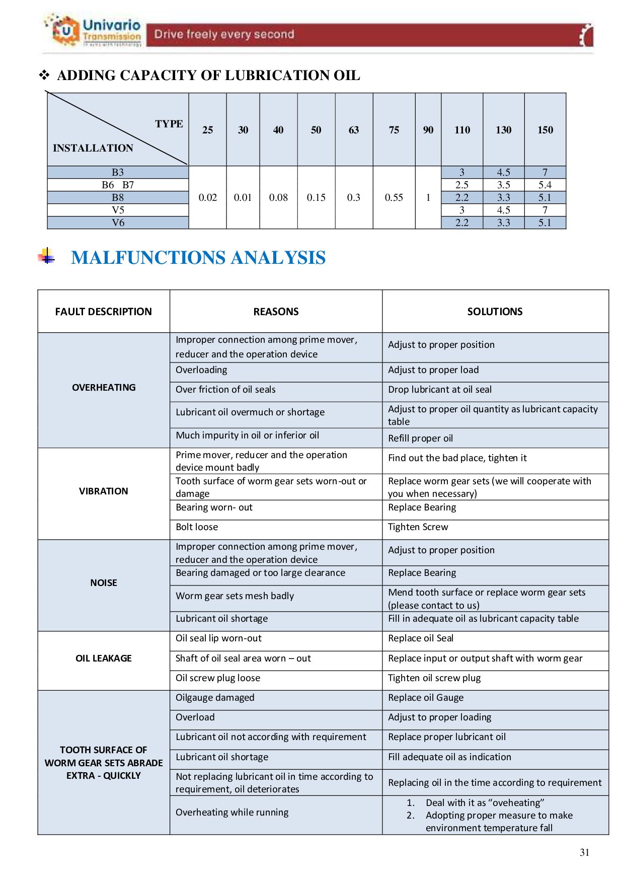
  23.  ADDING CAPACITY OF LUBRICATION OIL TYPE INSTALLATION 25 30

    40 50 63 75 90 110 130 150 B3 0.02 0.01 0.08 0.15 0.3 0.55 1 3 4.5 7 B6 B7 2.5 3.5 5.4 B8 2.2 3.3 5.1 V5 3 4.5 7 V6 2.2 3.3 5.1 MALFUNCTIONS ANALYSIS FAULT DESCRIPTION REASONS SOLUTIONS OVERHEATING Improper connection among prime mover, reducer and the operation device Adjust to proper position Overloading Adjust to proper load Over friction of oil seals Drop lubricant at oil seal Lubricant oil overmuch or shortage Adjust to proper oil quantity as lubricant capacity table Much impurity in oil or inferior oil Refill proper oil VIBRATION Prime mover, reducer and the operation device mount badly Find out the bad place, tighten it Tooth surface of worm gear sets worn-out or damage Replace worm gear sets (we will cooperate with you when necessary) Bearing worn- out Replace Bearing Bolt loose Tighten Screw NOISE Improper connection among prime mover, reducer and the operation device Adjust to proper position Bearing damaged or too large clearance Replace Bearing Worm gear sets mesh badly Mend tooth surface or replace worm gear sets (please contact to us) Lubricant oil shortage Fill in adequate oil as lubricant capacity table OIL LEAKAGE Oil seal lip worn-out Replace oil Seal Shaft of oil seal area worn – out Replace input or output shaft with worm gear Oil screw plug loose Tighten oil screw plug TOOTH SURFACE OF WORM GEAR SETS ABRADE EXTRA - QUICKLY Oilgauge damaged Replace oil Gauge Overload Adjust to proper loading Lubricant oil not according with requirement Replace proper lubricant oil Lubricant oil shortage Fill adequate oil as indication Not replacing lubricant oil in time according to requirement, oil deteriorates Replacing oil in the time according to requirement Overheating while running 1. Deal with it as “oveheating” 2. Adopting proper measure to make environment temperature fall 31