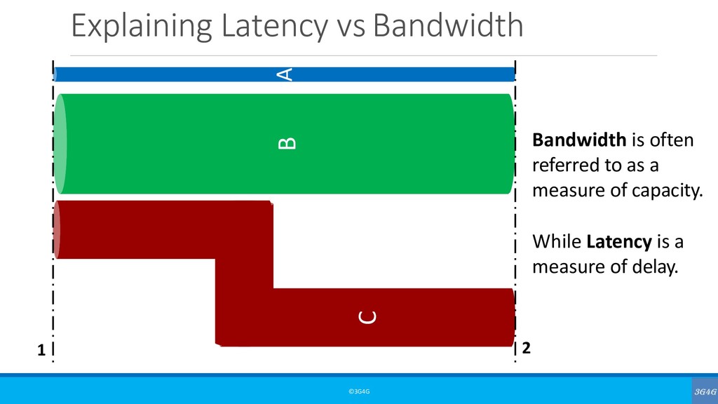
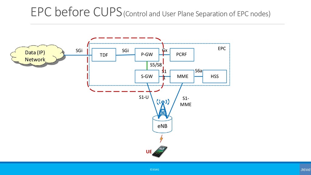
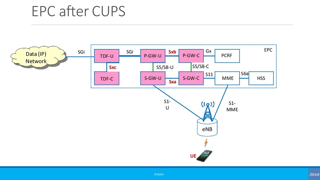
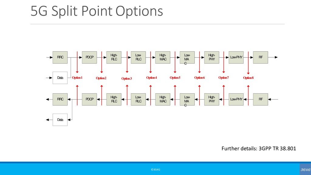
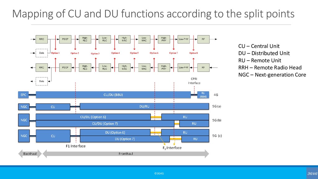
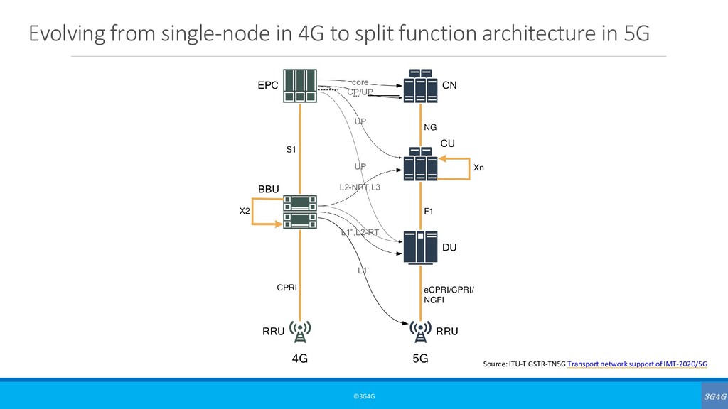
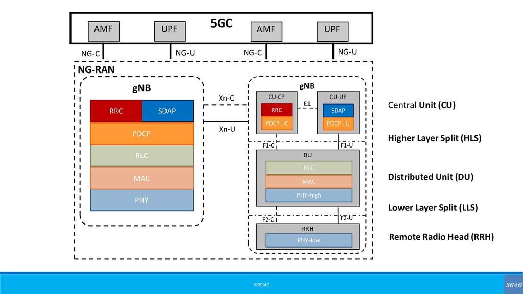
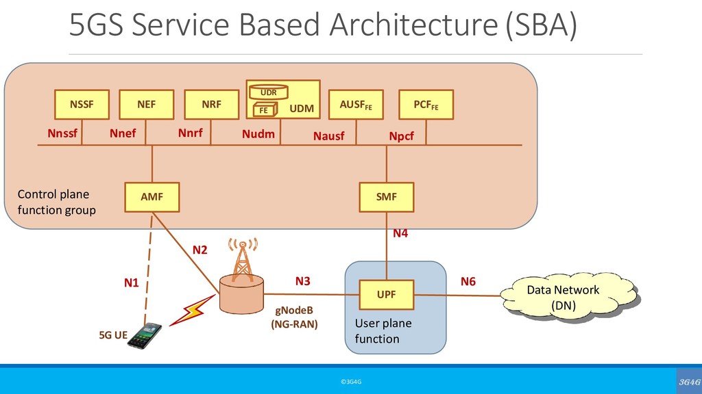
time it takes for a source to send a packet of data to a receiver. In simple terms, half of Ping time. This is also referred to as one way latency. Sometimes the term Round trip latency or round trip time (RTT) is also used to define latency. This is the same as ping time. Jitter is defined as the variation in the delay (or latency) of received packets. It is also referred to as ‘delay jitter’.
takes to transfer a given piece of information from a source to a destination, measured at the communication interface, from the moment it is transmitted by the source to the moment it is successfully received at the destination.
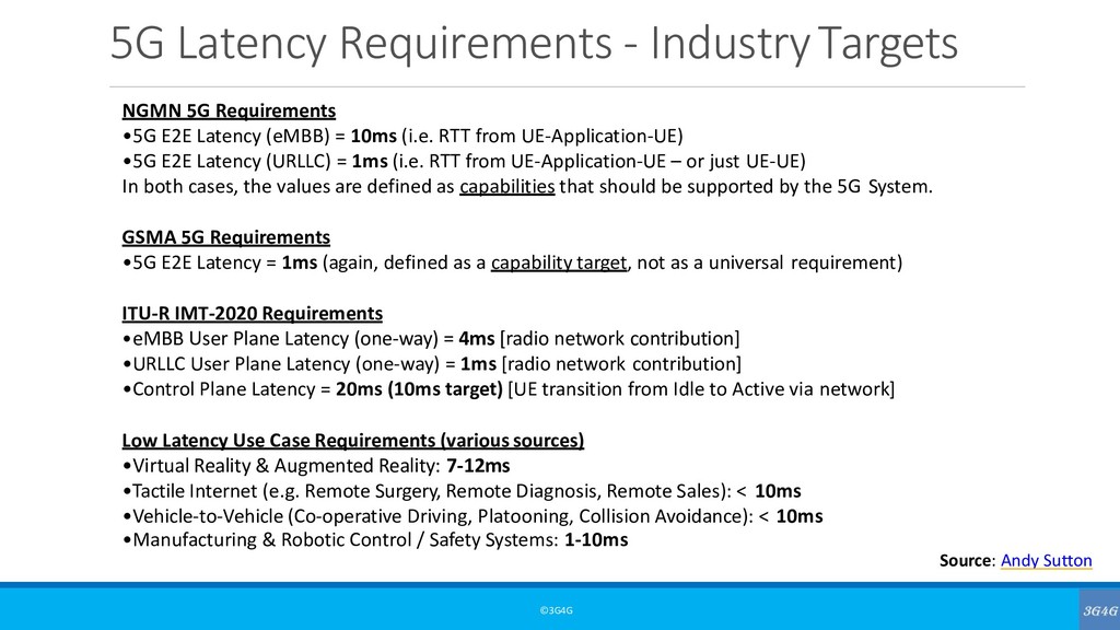
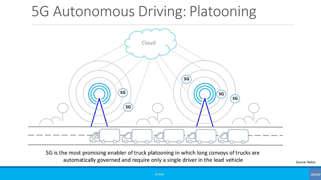
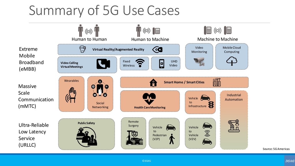
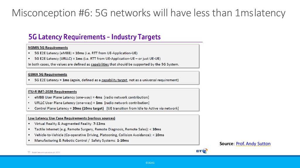
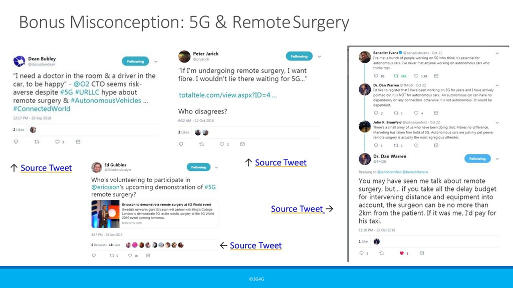
E2E Latency (eMBB) = 10ms (i.e. RTT from UE-Application-UE) •5G E2E Latency (URLLC) = 1ms (i.e. RTT from UE-Application-UE – or just UE-UE) In both cases, the values are defined as capabilities that should be supported by the 5G System. GSMA 5G Requirements •5G E2E Latency = 1ms (again, defined as a capability target, not as a universal requirement) ITU-R IMT-2020 Requirements •eMBB User Plane Latency (one-way) = 4ms [radio network contribution] •URLLC User Plane Latency (one-way) = 1ms [radio network contribution] •Control Plane Latency = 20ms (10ms target) [UE transition from Idle to Active via network] Low Latency Use Case Requirements (various sources) •Virtual Reality & Augmented Reality: 7-12ms •Tactile Internet (e.g. Remote Surgery, Remote Diagnosis, Remote Sales): < 10ms •Vehicle-to-Vehicle (Co-operative Driving, Platooning, Collision Avoidance): < 10ms •Manufacturing & Robotic Control / Safety Systems: 1-10ms Source: Andy Sutton
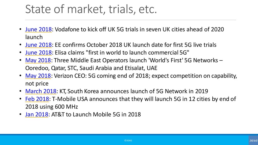
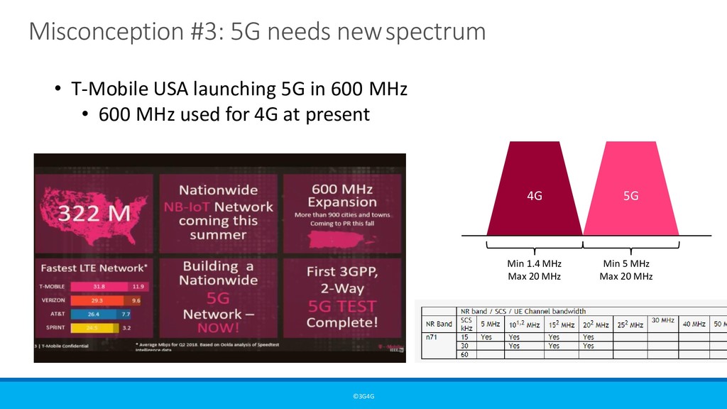
to kick off UK 5G trials in seven UK cities ahead of 2020 launch • June 2018: EE confirms October 2018 UK launch date for first 5G live trials • June 2018: Elisa claims "first in world to launch commercial 5G" • May 2018: Three Middle East Operators launch 'World's First' 5G Networks – Ooredoo, Qatar, STC, Saudi Arabia and Etisalat, UAE • May 2018: Verizon CEO: 5G coming end of 2018; expect competition on capability, not price • March 2018: KT, South Korea announces launch of 5G Network in 2019 • Feb 2018: T-Mobile USA announces that they will launch 5G in 12 cities by end of 2018 using 600 MHz • Jan 2018: AT&T to Launch Mobile 5G in 2018
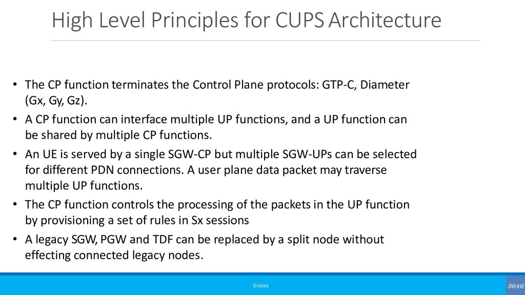
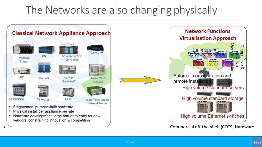
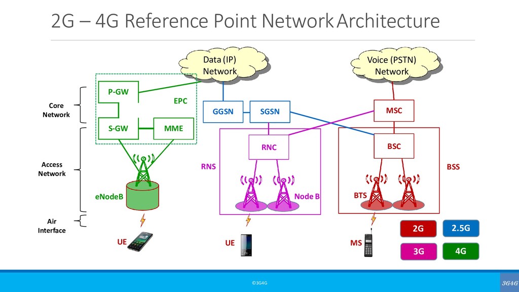
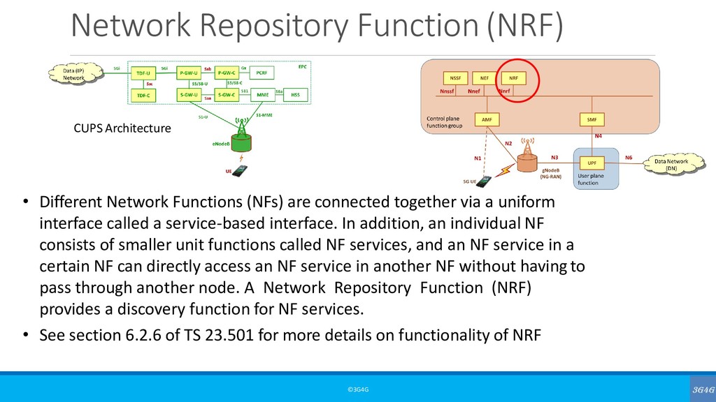
terminates the Control Plane protocols: GTP-C, Diameter (Gx, Gy, Gz). • A CP function can interface multiple UP functions, and a UP function can be shared by multiple CP functions. • An UE is served by a single SGW-CP but multiple SGW-UPs can be selected for different PDN connections. A user plane data packet may traverse multiple UP functions. • The CP function controls the processing of the packets in the UP function by provisioning a set of rules in Sx sessions • A legacy SGW, PGW and TDF can be replaced by a split node without effecting connected legacy nodes.
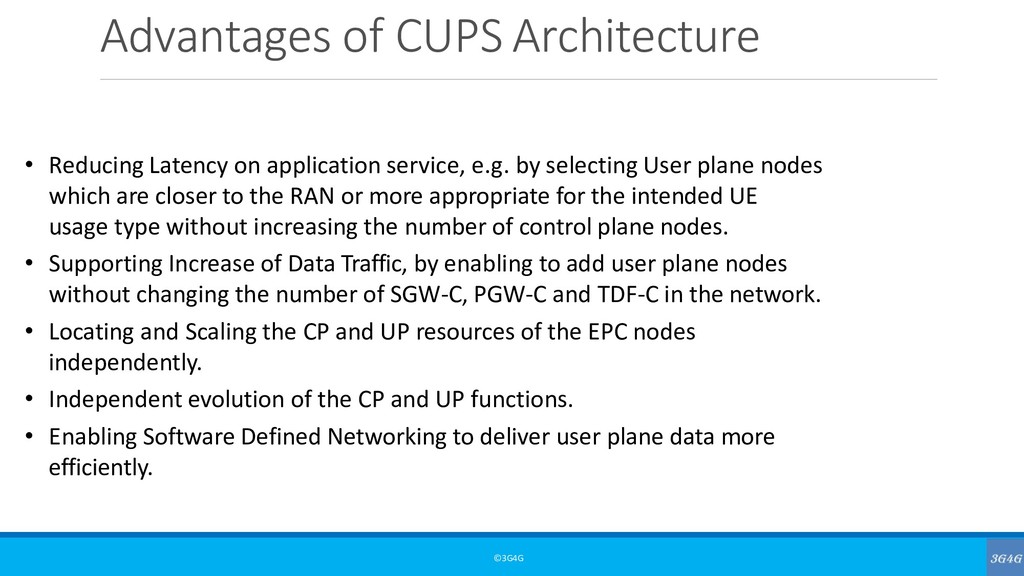
service, e.g. by selecting User plane nodes which are closer to the RAN or more appropriate for the intended UE usage type without increasing the number of control plane nodes. • Supporting Increase of Data Traffic, by enabling to add user plane nodes without changing the number of SGW-C, PGW-C and TDF-C in the network. • Locating and Scaling the CP and UP resources of the EPC nodes independently. • Independent evolution of the CP and UP functions. • Enabling Software Defined Networking to deliver user plane data more efficiently.
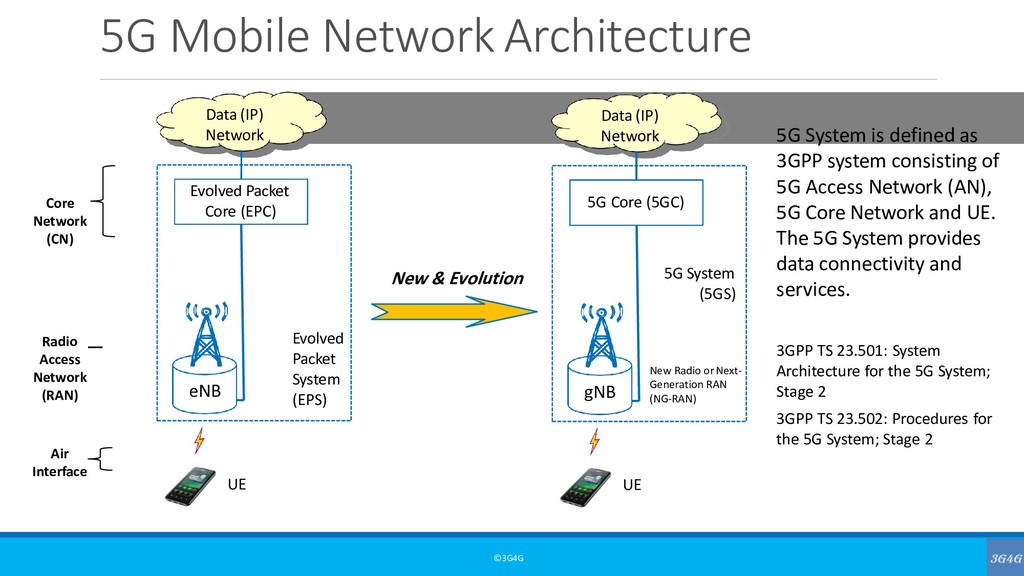
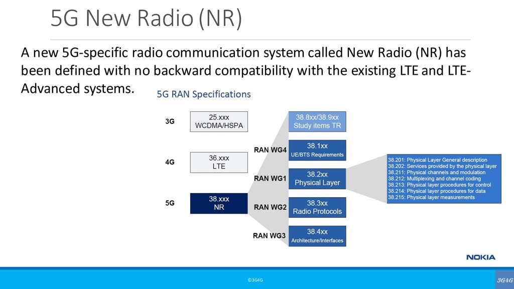
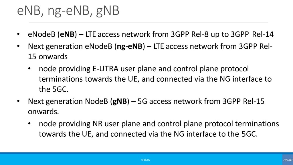
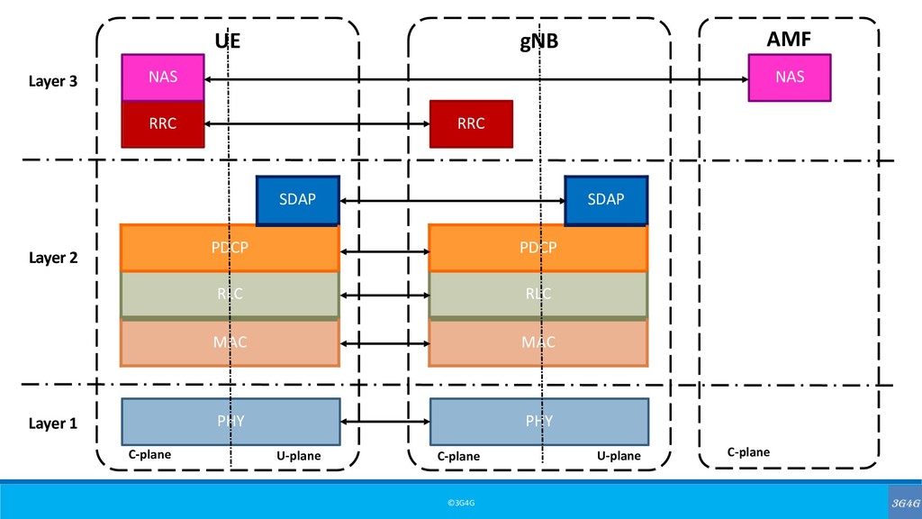
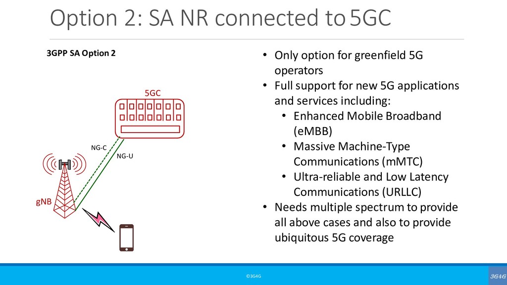
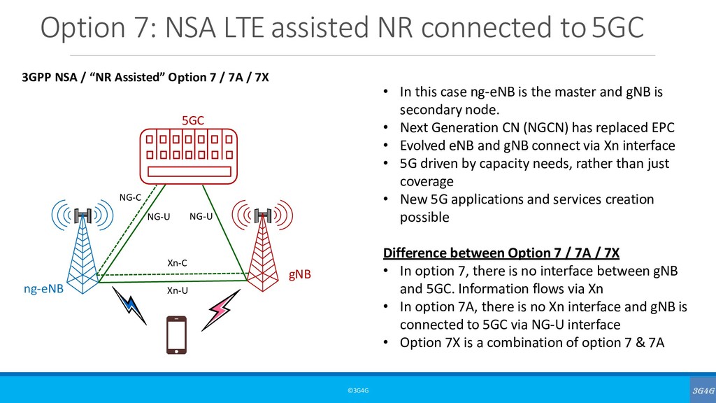
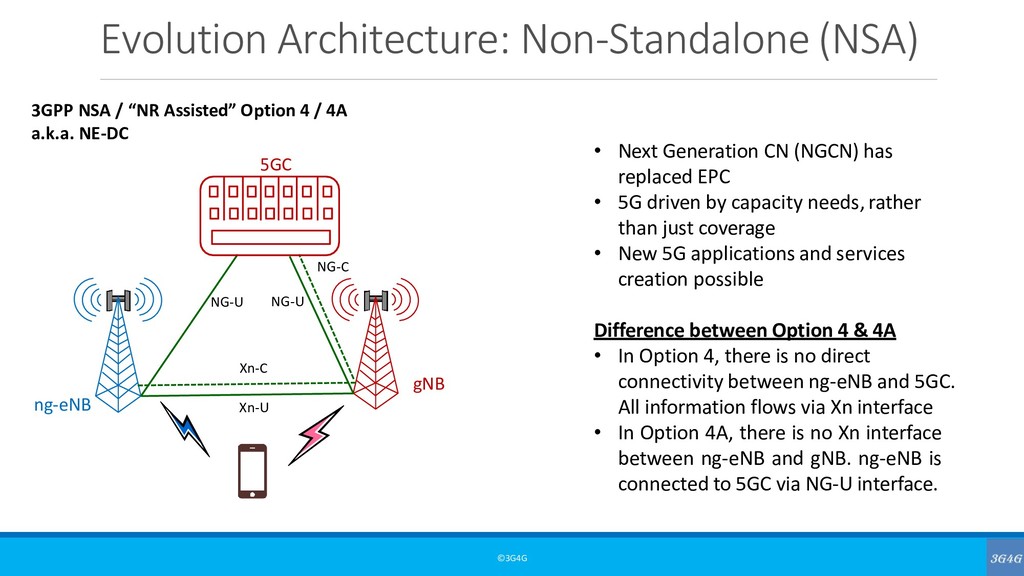
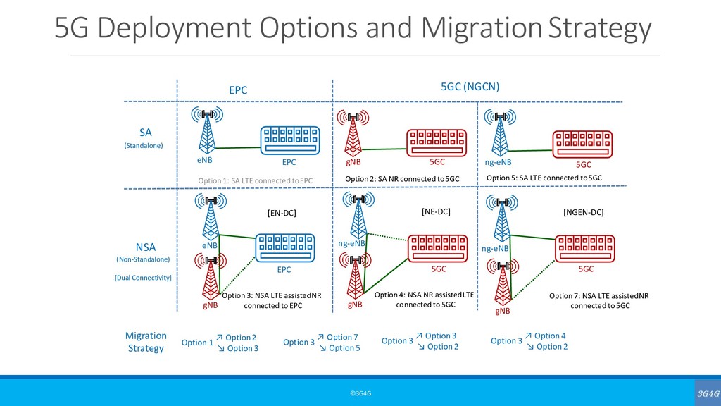
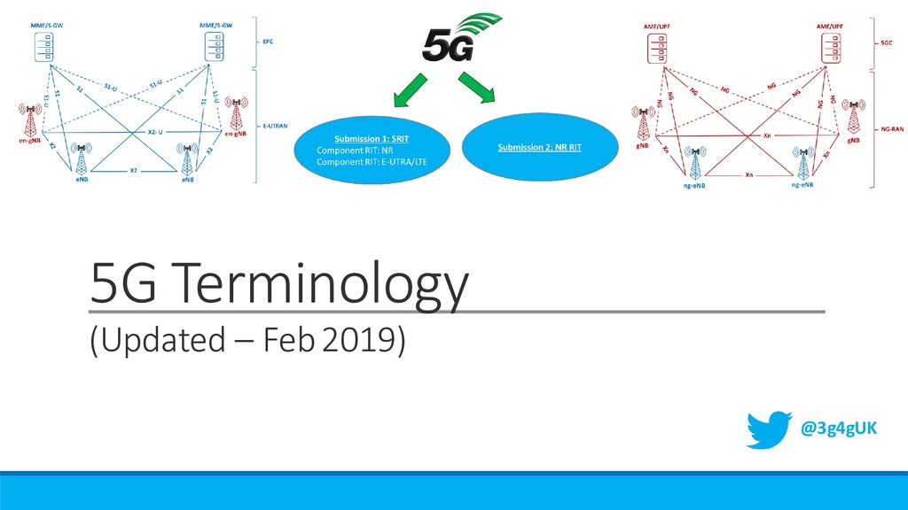
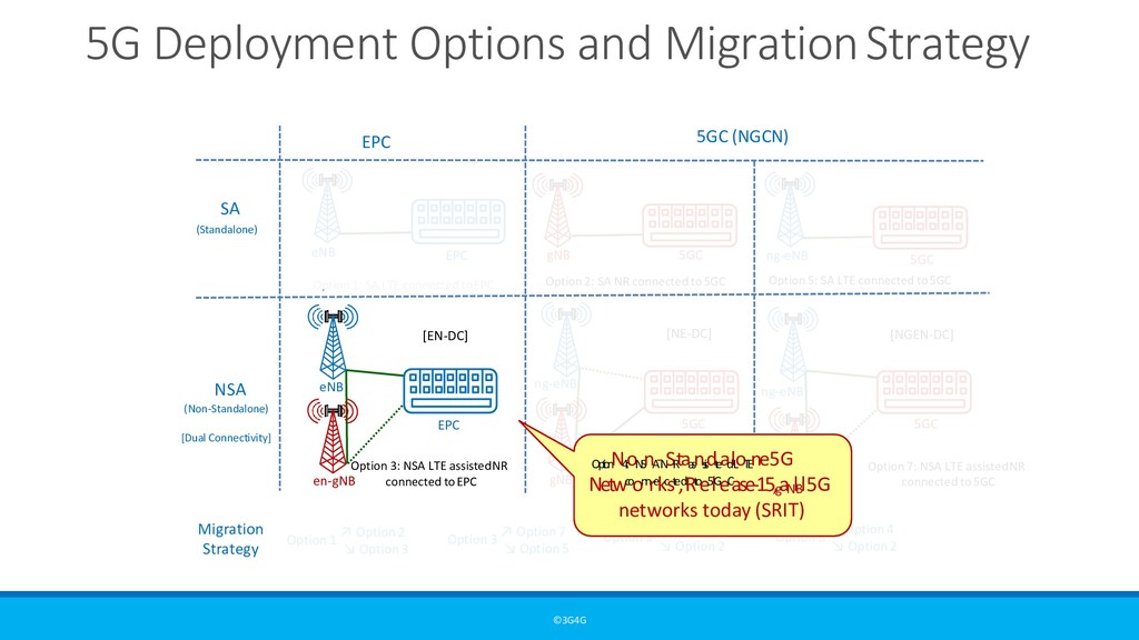
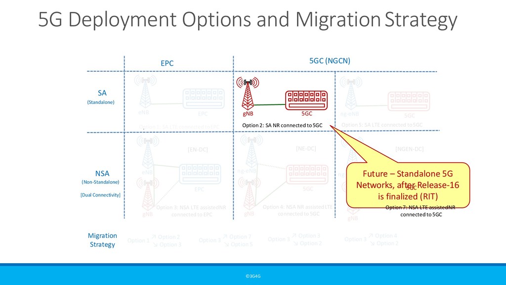
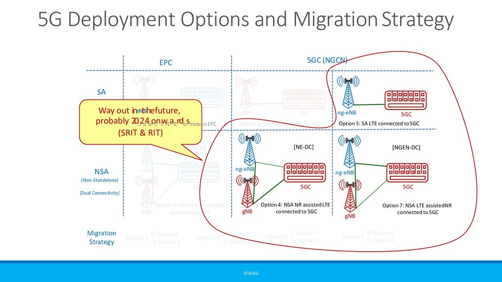
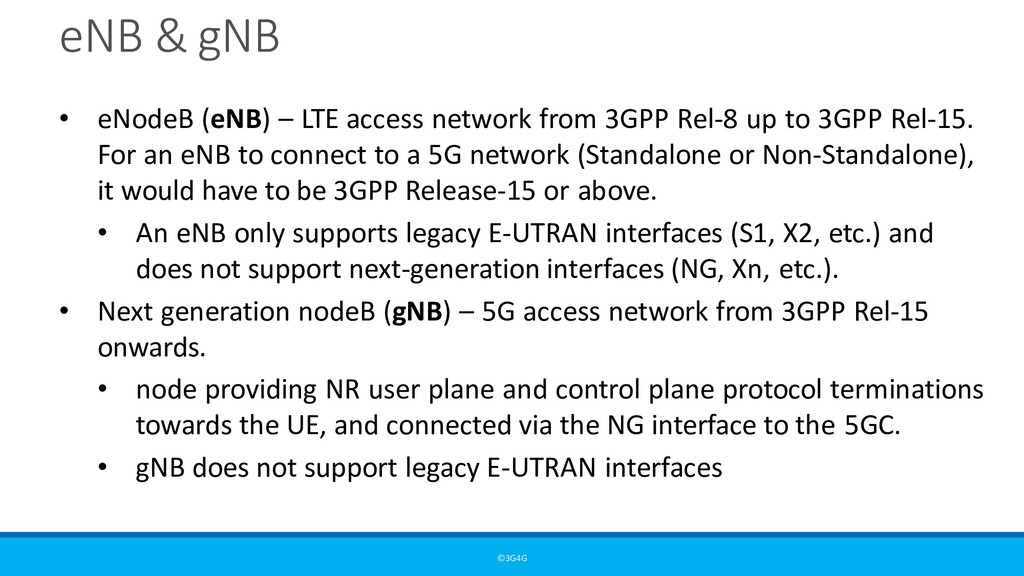
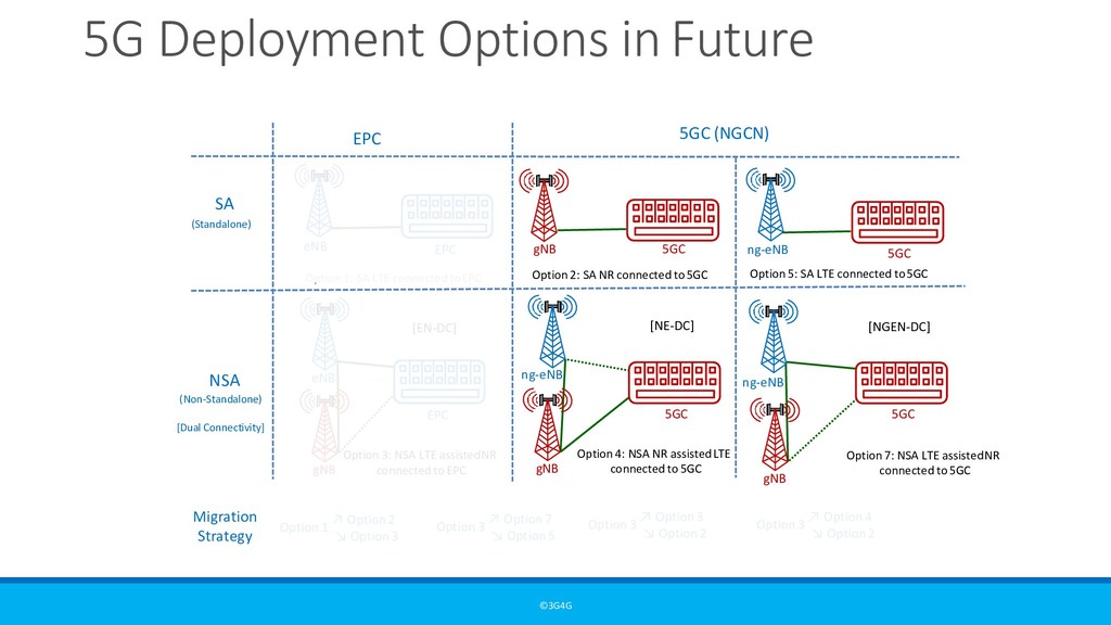
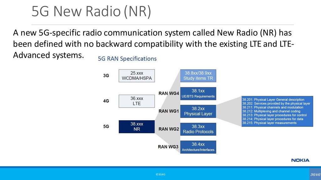
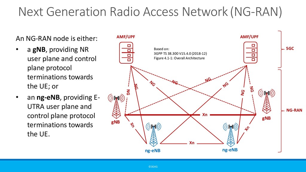
network from 3GPP Rel-8 up to 3GPP Rel-14 • Next generation eNodeB (ng-eNB) – LTE access network from 3GPP Rel- 15 onwards • node providing E-UTRA user plane and control plane protocol terminations towards the UE, and connected via the NG interface to the 5GC. • Next generation NodeB (gNB) – 5G access network from 3GPP Rel-15 onwards. • node providing NR user plane and control plane protocol terminations towards the UE, and connected via the NG interface to the 5GC.
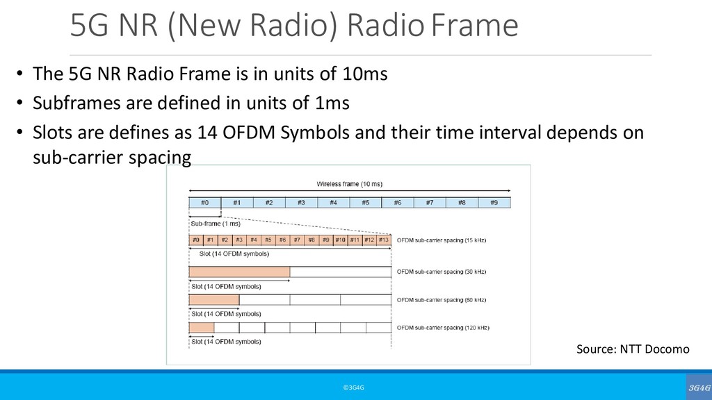
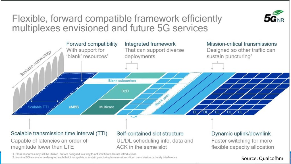
Radio Frame is in units of 10ms • Subframes are defined in units of 1ms • Slots are defines as 14 OFDM Symbols and their time interval depends on sub-carrier spacing Source: NTT Docomo
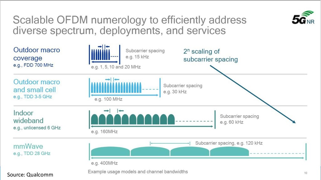
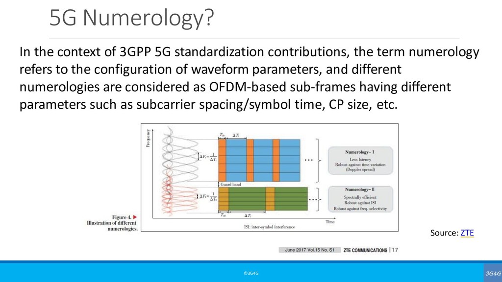
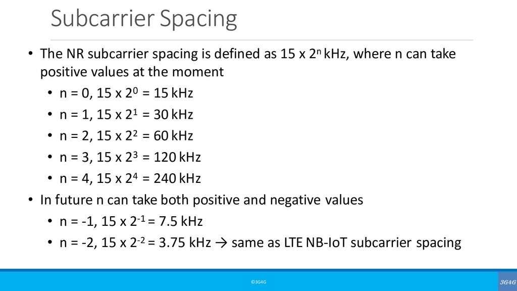
as 15 x 2n kHz, where n can take positive values at the moment • n = 0, 15 x 20 = 15 kHz • n = 1, 15 x 21 = 30 kHz • n = 2, 15 x 22 = 60 kHz • n = 3, 15 x 23 = 120 kHz • n = 4, 15 x 24 = 240 kHz • In future n can take both positive and negative values • n = -1, 15 x 2-1 = 7.5 kHz • n = -2, 15 x 2-2 = 3.75 kHz → same as LTE NB-IoT subcarrier spacing
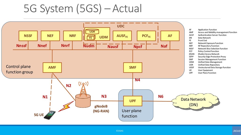
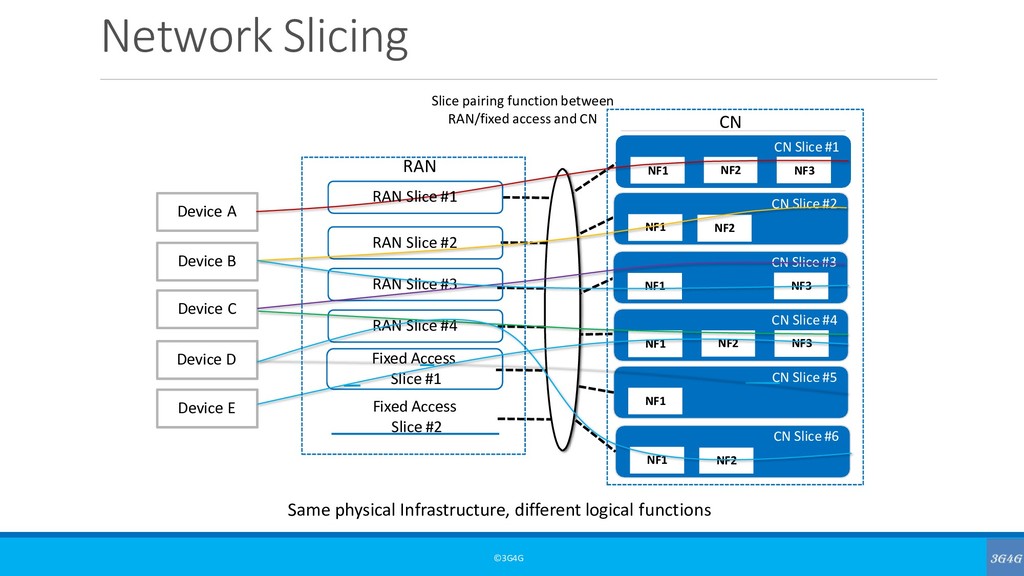
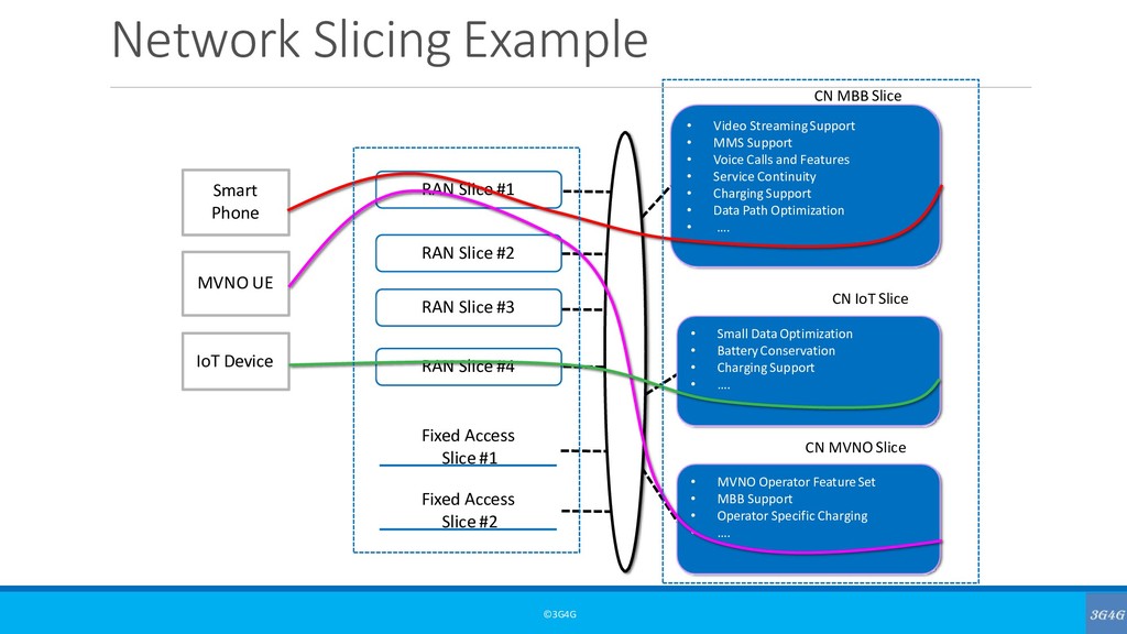
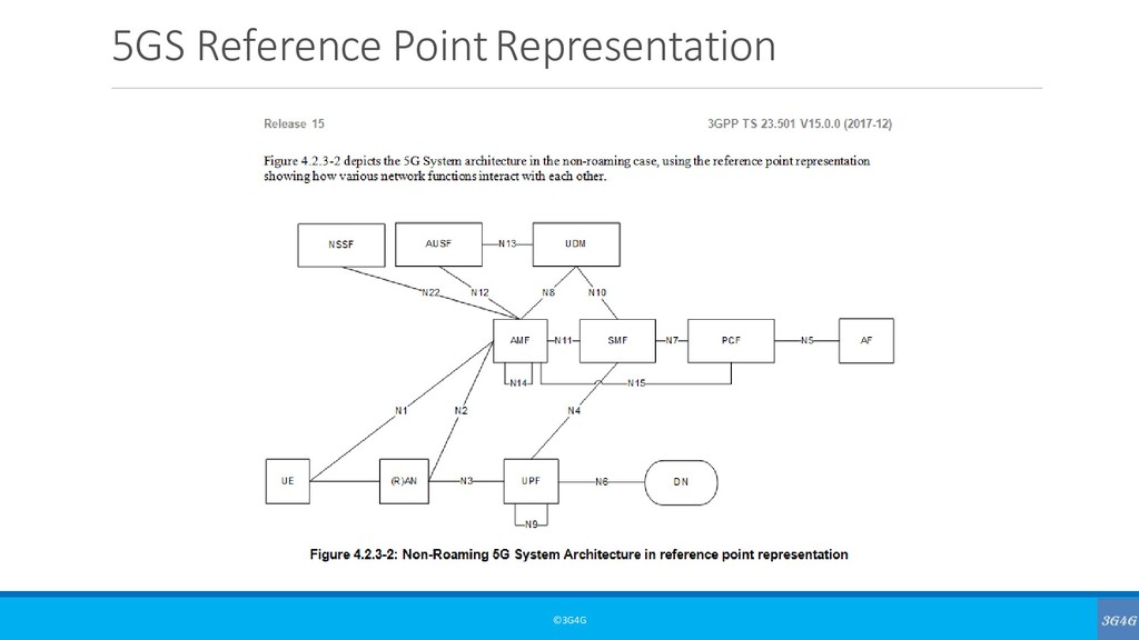
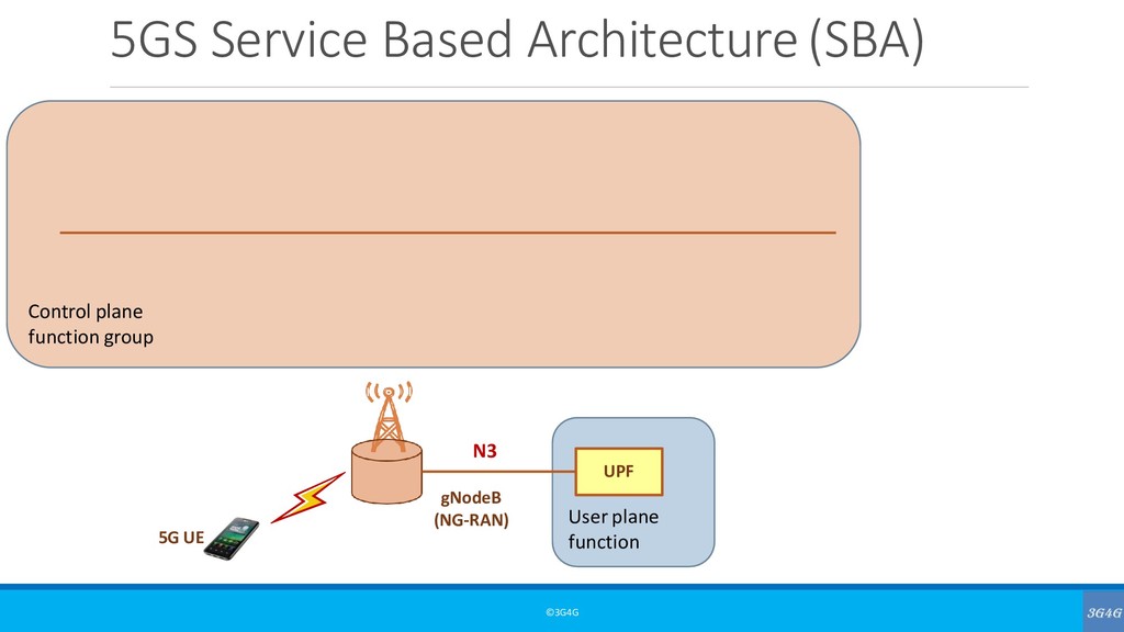
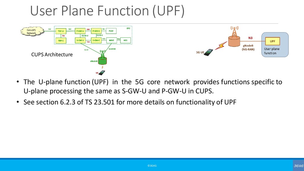
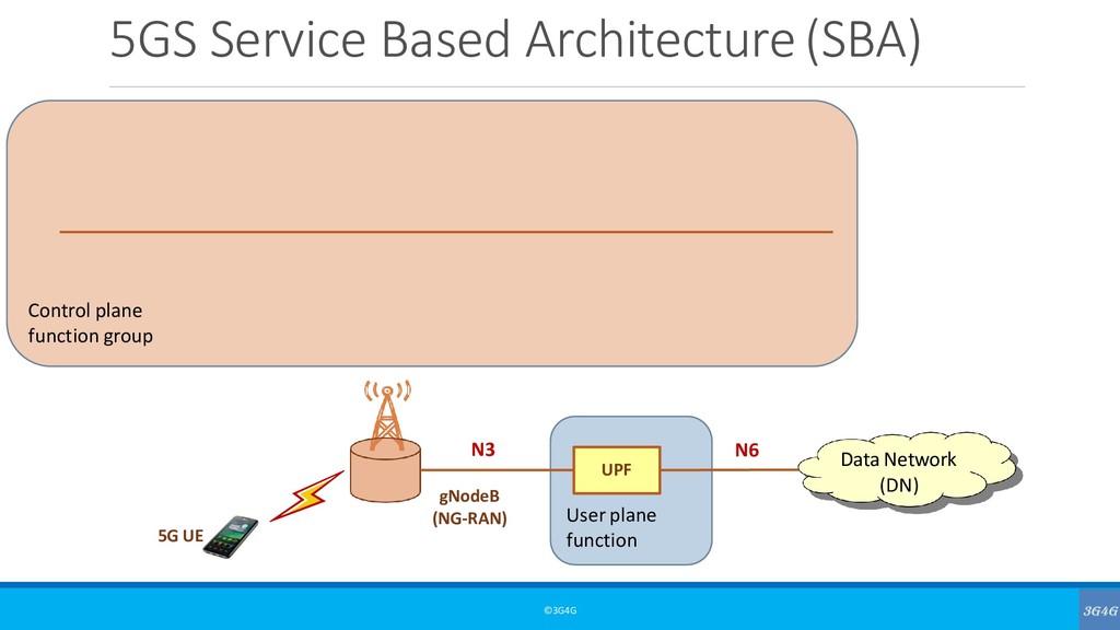
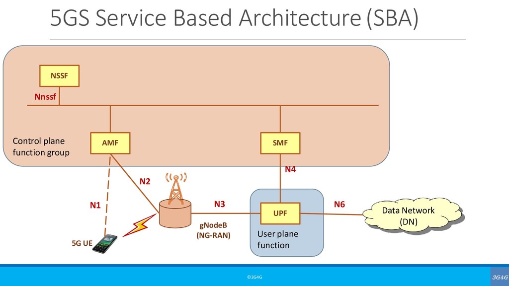
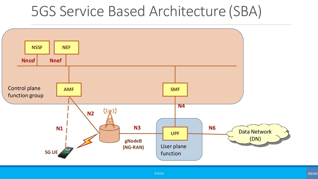
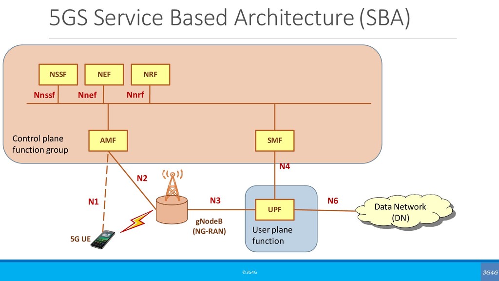
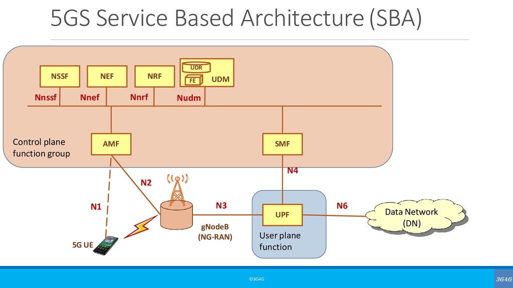
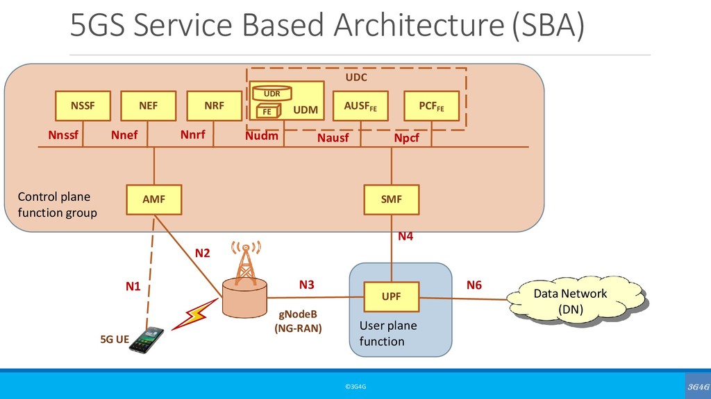
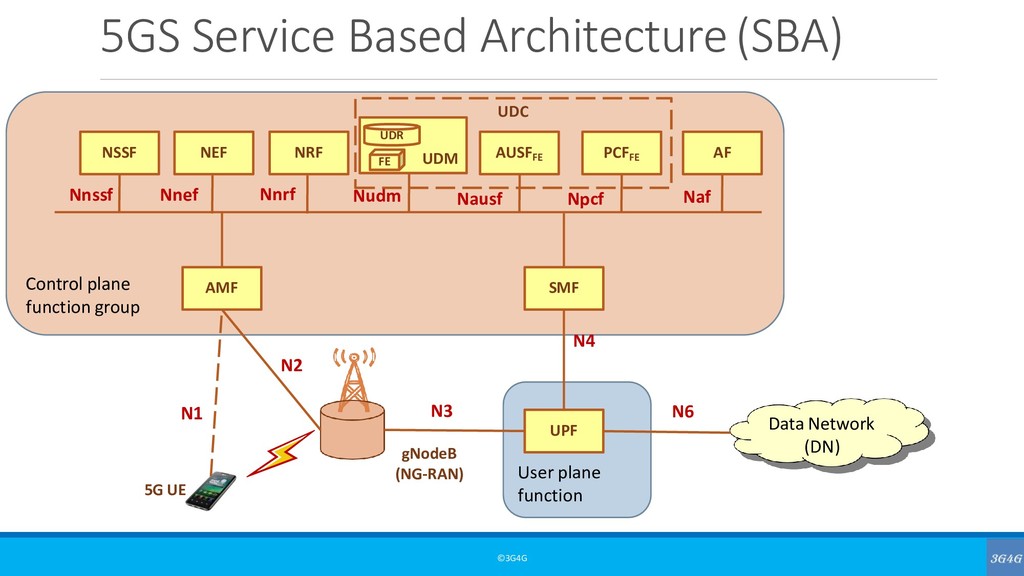
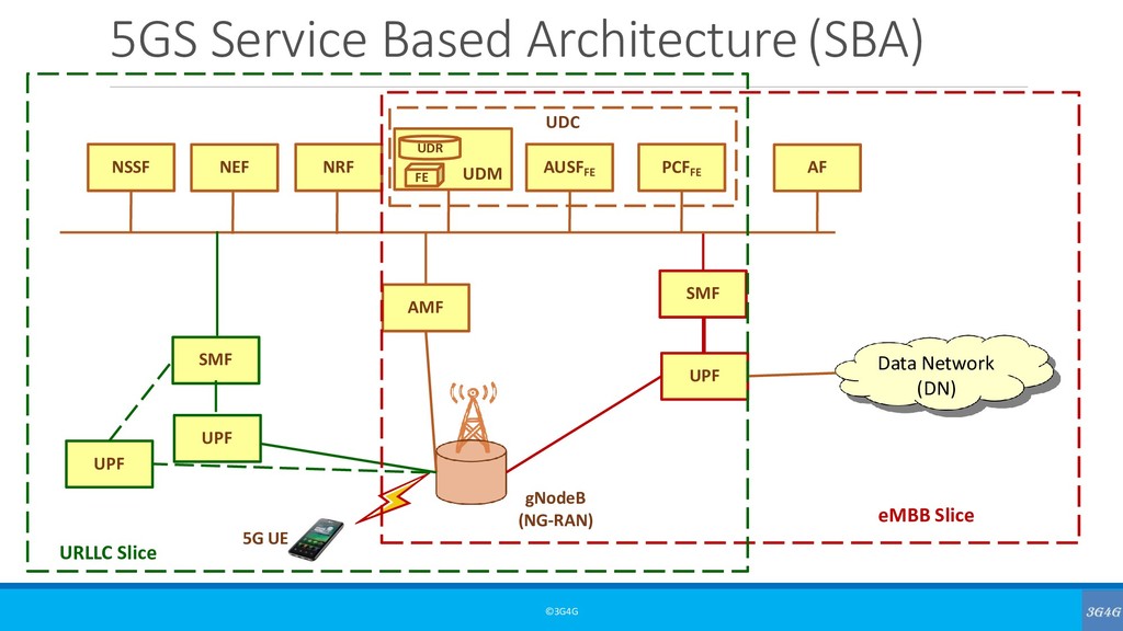
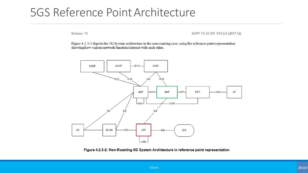
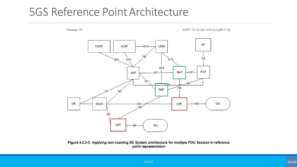
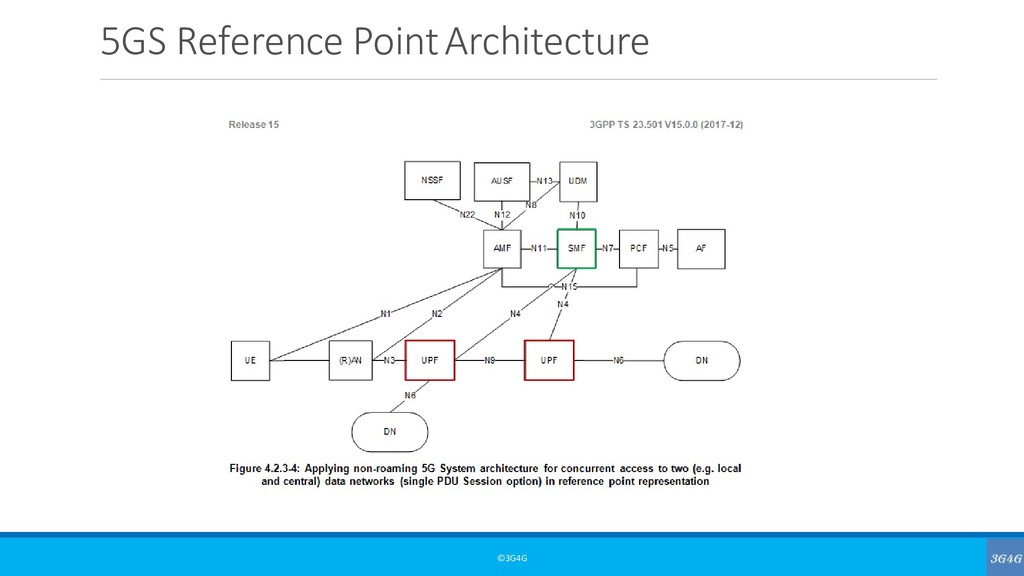
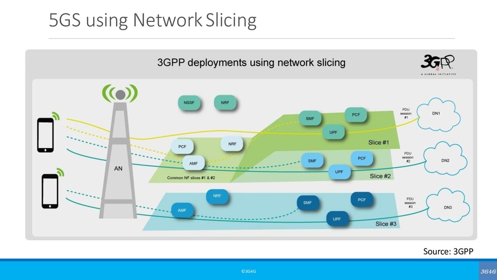
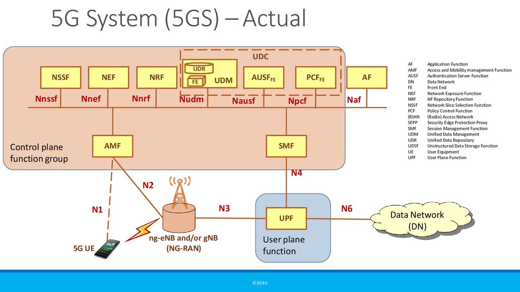
23.501 - The User plane function (UPF) includes the following functionality. Some or all of the UPF functionalities may be supported in a single instance of a UPF: • Anchor point for Intra-/Inter-RAT mobility (when applicable). • External PDU Session point of interconnect to Data Network. • Packet routing & forwarding (e.g. support of Uplink classifier to route traffic flows to an instance of a data network, support of Branching point to support multi-homed PDU session). • Packet inspection (e.g. Application detection based on service data flow template and the optional PFDs received from the SMF in addition). • User Plane part of policy rule enforcement, e.g. Gating, Redirection, Traffic steering). • Lawful intercept (UP collection). • Traffic usage reporting. • QoS handling for user plane, e.g. UL/DL rate enforcement, Reflective QoS marking in DL. • Uplink Traffic verification (SDF to QoS Flow mapping). • Transport level packet marking in the uplink and downlink. • Downlink packet buffering and downlink data notification triggering. • Sending and forwarding of one or more "end marker" to the source NG-RAN node. • ARP proxying as specified in IETF RFC 1027 and / or IPv6 Neighbour Solicitation Proxying as specified in IETF RFC 4861 functionality for the Ethernet PDUs. The UPF responds to the ARP and / or the IPv6 Neighbour Solicitation Request by providing the MAC address corresponding to the IP address sent in the request. NOTE:Not all of the UPF functionalities are required to be supported in an instance of user plane function of a Network Slice.
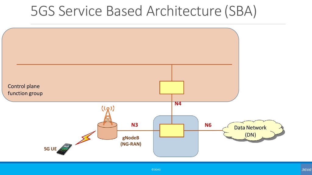
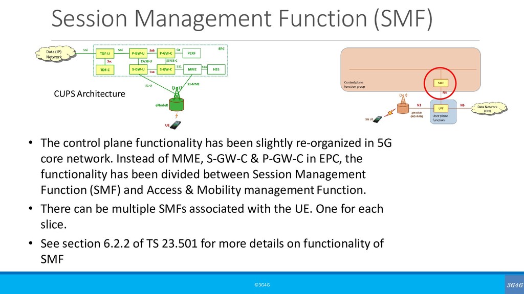
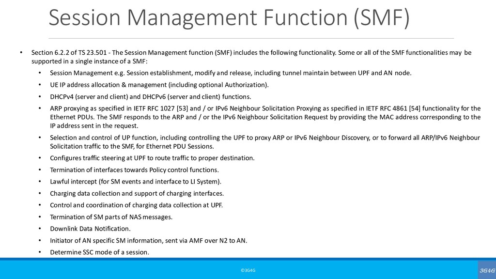
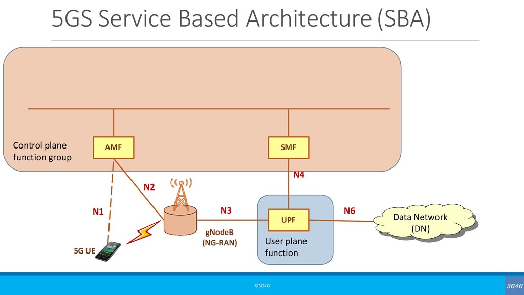
23.501 - The Session Management function (SMF) includes the following functionality. Some or all of the SMF functionalities may be supported in a single instance of a SMF: • Session Management e.g. Session establishment, modify and release, including tunnel maintain between UPF and AN node. • UE IP address allocation & management (including optional Authorization). • DHCPv4 (server and client) and DHCPv6 (server and client) functions. • ARP proxying as specified in IETF RFC 1027 [53] and / or IPv6 Neighbour Solicitation Proxying as specified in IETF RFC 4861 [54] functionality for the Ethernet PDUs. The SMF responds to the ARP and / or the IPv6 Neighbour Solicitation Request by providing the MAC address corresponding to the IP address sent in the request. • Selection and control of UP function, including controlling the UPF to proxy ARP or IPv6 Neighbour Discovery, or to forward all ARP/IPv6 Neighbour Solicitation traffic to the SMF,for Ethernet PDU Sessions. • Configures traffic steering at UPF to route traffic to proper destination. • Termination of interfaces towards Policy control functions. • Lawful intercept (for SM events and interface to LI System). • Charging data collection and support of charging interfaces. • Control and coordination of charging data collection at UPF. • Termination of SM parts of NAS messages. • Downlink Data Notification. • Initiator of AN specific SM information, sent via AMF over N2 to AN. • Determine SSC mode of a session.
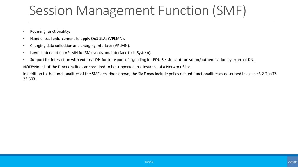
local enforcement to apply QoS SLAs (VPLMN). • Charging data collection and charging interface (VPLMN). • Lawful intercept (in VPLMN for SM events and interface to LI System). • Support for interaction with external DN for transport of signalling for PDU Session authorization/authentication by external DN. NOTE:Not all of the functionalities are required to be supported in a instance of a Network Slice. In addition to the functionalities of the SMF described above, the SMF may include policy related functionalities as described in clause 6.2.2 in TS 23.503.
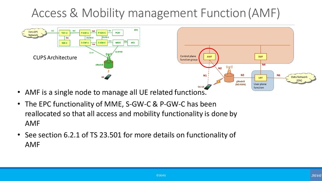
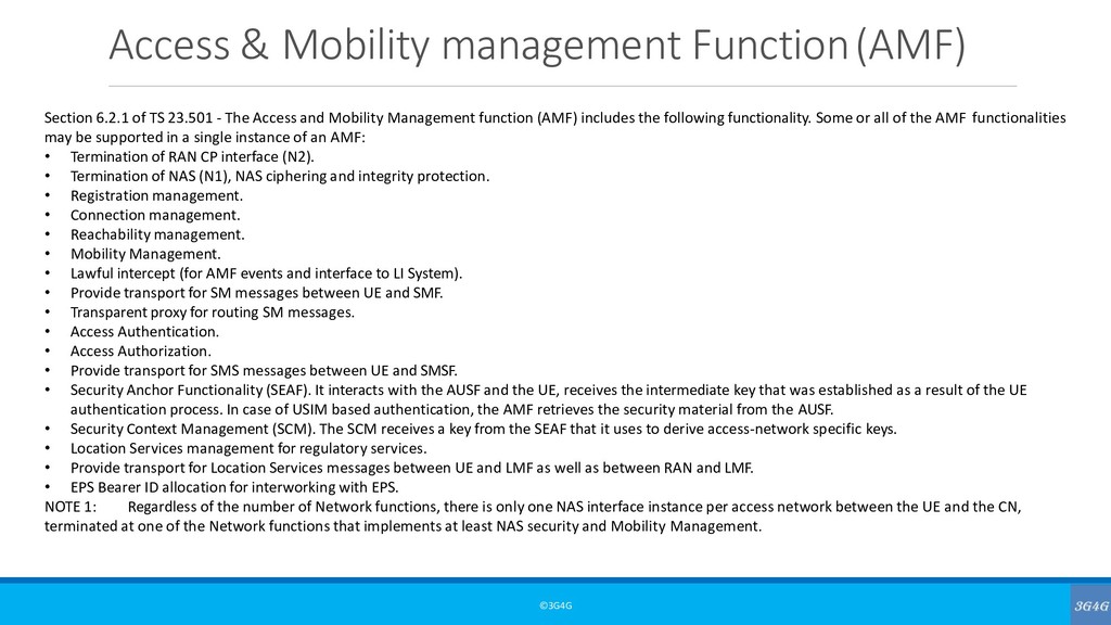
23.501 - The Access and Mobility Management function (AMF) includes the following functionality. Some or all of the AMF functionalities may be supported in a single instance of an AMF: • Termination of RAN CP interface (N2). • Termination of NAS (N1), NAS ciphering and integrity protection. • Registration management. • Connection management. • Reachability management. • Mobility Management. • Lawful intercept (for AMF events and interface to LI System). • Provide transport for SM messages between UE and SMF. • Transparent proxy for routing SM messages. • Access Authentication. • Access Authorization. • Provide transport for SMS messages between UE and SMSF. • Security Anchor Functionality (SEAF). It interacts with the AUSF and the UE, receives the intermediate key that was established as a result of the UE authentication process. In case of USIM based authentication, the AMF retrieves the security material from the AUSF. • Security Context Management (SCM). The SCM receives a key from the SEAF that it uses to derive access-network specific keys. • Location Services management for regulatory services. • Provide transport for Location Services messages between UE and LMF as well as between RAN and LMF. • EPS Bearer ID allocation for interworking with EPS. NOTE 1: Regardless of the number of Network functions, there is only one NAS interface instance per access network between the UE and the CN, terminated at one of the Network functions that implements at least NAS security and Mobility Management.
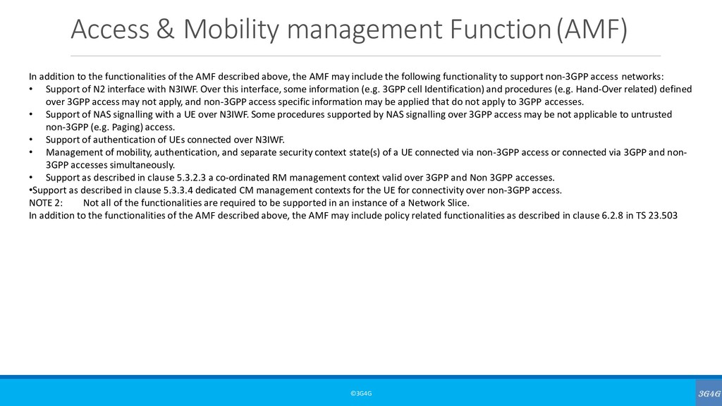
functionalities of the AMF described above, the AMF may include the following functionality to support non-3GPP access networks: • Support of N2 interface with N3IWF. Over this interface, some information (e.g. 3GPP cell Identification) and procedures (e.g. Hand-Over related) defined over 3GPP access may not apply, and non-3GPP access specific information may be applied that do not apply to 3GPP accesses. • Support of NAS signalling with a UE over N3IWF. Some procedures supported by NAS signalling over 3GPP access may be not applicable to untrusted non-3GPP (e.g. Paging) access. • Support of authentication of UEs connected over N3IWF. • Management of mobility, authentication, and separate security context state(s) of a UE connected via non-3GPP access or connected via 3GPP and non- 3GPP accesses simultaneously. • Support as described in clause 5.3.2.3 a co-ordinated RM management context valid over 3GPP and Non 3GPP accesses. •Support as described in clause 5.3.3.4 dedicated CM management contexts for the UE for connectivity over non-3GPP access. NOTE 2: Not all of the functionalities are required to be supported in an instance of a Network Slice. In addition to the functionalities of the AMF described above, the AMF may include policy related functionalities as described in clause 6.2.8 in TS 23.503
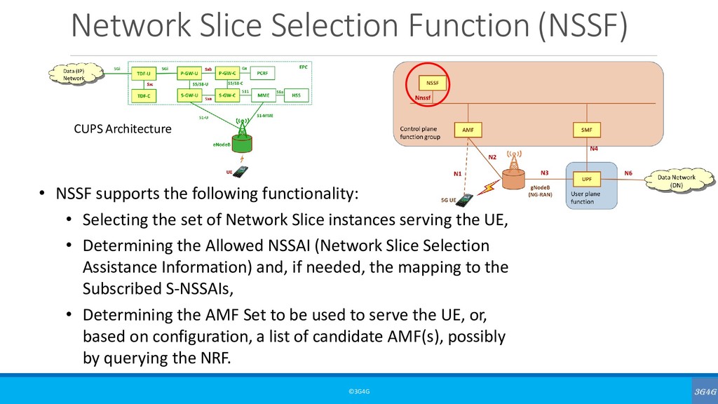
23.501 - The Network Slice Selection Function (NSSF) supports the followingfunctionality: • Selecting the set of Network Slice instances serving the UE, • Determining the Allowed NSSAI and, if needed, the mapping to the Subscribed S-NSSAIs, • Determining the AMF Set to be used to serve the UE, or, based on configuration, a list of candidate AMF(s), possibly by querying the NRF.
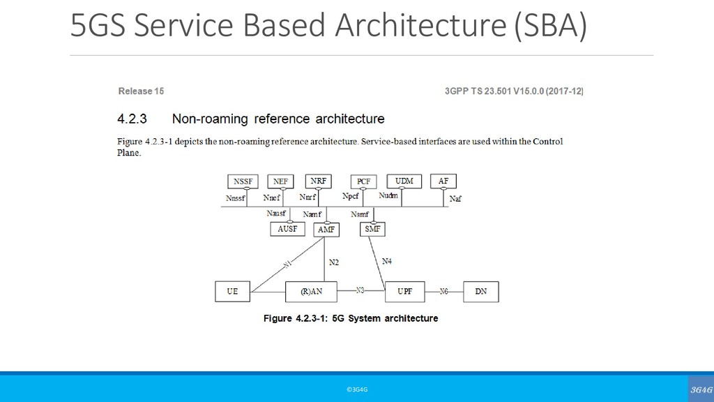
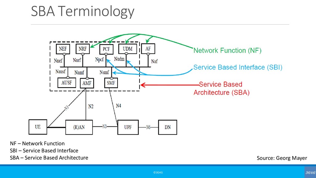
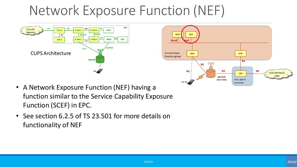
- The Network Exposure Function (NEF) supports the following independent functionality: • Exposure of capabilities and events: 3GPP NFs expose capabilities and events to other NFs via NEF. NF exposed capabilities and events may be securely exposed for e.g. 3rd party, Application Functions, Edge Computing as described in clause 5.13. NEF stores/retrieves information as structured data using a standardized interface (Nudr) to the Unified Data Repository (UDR). NOTE:The NEF can access the UDR located in the same PLMN as the NEF. • Secure provision of information from external application to 3GPP network: It provides a means for the Application Functions to securely provide information to 3GPP network, e.g. Expected UE Behaviour. In that case the NEF may authenticate and authorize and assist in throttling the Application Functions. • Translation of internal-external information: It translates between information exchanged with the AF and information exchanged with the internal network function. For example, it translates between an AF-Service-Identifier and internal 5G Core information such as DNN, S-NSSAI, as described in clause 5.6.7. In particular, NEF handles masking of network and user sensitive information to external AF's according to the network policy. • The Network Exposure Function receives information from other network functions (based on exposed capabilities of other network functions). NEF stores the received information as structured data using a standardized interface to a Unified Data Repository (UDR) (interface to be defined by 3GPP). The stored information can be accessed and "re-exposed" by the NEF to other network functions and Application Functions, and used for other purposes such as analytics. • A NEF may also support a PFD Function: The PFD Function in the NEF may store and retrieve PFD(s) in the UDR and shall provide PFD(s) to the SMF on the request of SMF (pull mode) or on the request of PFD management from NEF (push mode), as described in TS 23.503. A specific NEF instance may support one or more of the functionalities described above and consequently an individual NEF may support a subset of the APIs specified for capability exposure. NOTE:The NEF can access the UDR located in the same PLMN as the NEF.
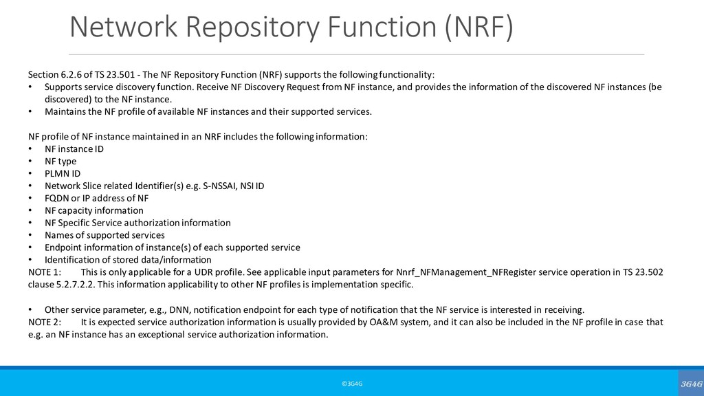
- The NF Repository Function (NRF) supports the followingfunctionality: • Supports service discovery function. Receive NF Discovery Request from NF instance, and provides the information of the discovered NF instances (be discovered) to the NF instance. • Maintains the NF profile of available NF instances and their supported services. NF profile of NF instance maintained in an NRF includes the followinginformation: • NF instance ID • NF type • PLMN ID • Network Slice related Identifier(s) e.g. S-NSSAI, NSI ID • FQDN or IP address of NF • NF capacity information • NF Specific Service authorization information • Names of supported services • Endpoint information of instance(s) of each supported service • Identification of stored data/information NOTE 1: This is only applicable for a UDR profile. See applicable input parameters for Nnrf_NFManagement_NFRegister service operation in TS 23.502 clause 5.2.7.2.2. This information applicability to other NF profiles is implementation specific. • Other service parameter, e.g., DNN, notification endpoint for each type of notification that the NF service is interested in receiving. NOTE 2: It is expected service authorization information is usually provided by OA&M system, and it can also be included in the NF profile in case that e.g. an NF instance has an exceptional service authorization information.
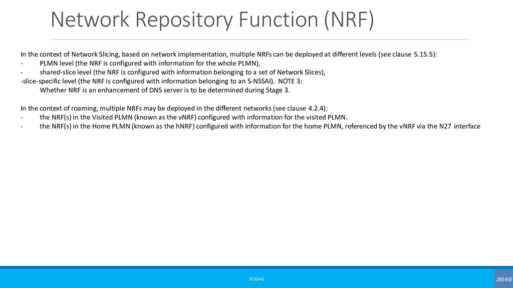
Slicing, based on network implementation, multiple NRFs can be deployed at different levels (see clause 5.15.5): - PLMN level (the NRF is configured with information for the whole PLMN), - shared-slice level (the NRF is configured with information belonging to a set of Network Slices), -slice-specific level (the NRF is configured with information belonging to an S-NSSAI). NOTE 3: Whether NRF is an enhancement of DNS server is to be determined during Stage 3. In the context of roaming, multiple NRFs may be deployed in the different networks (see clause 4.2.4): - the NRF(s) in the Visited PLMN (known as the vNRF) configured with information for the visited PLMN. - the NRF(s) in the Home PLMN (known as the hNRF) configured with information for the home PLMN, referenced by the vNRF via the N27 interface
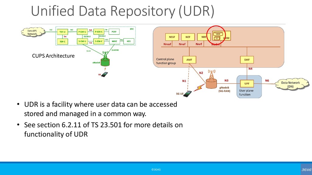
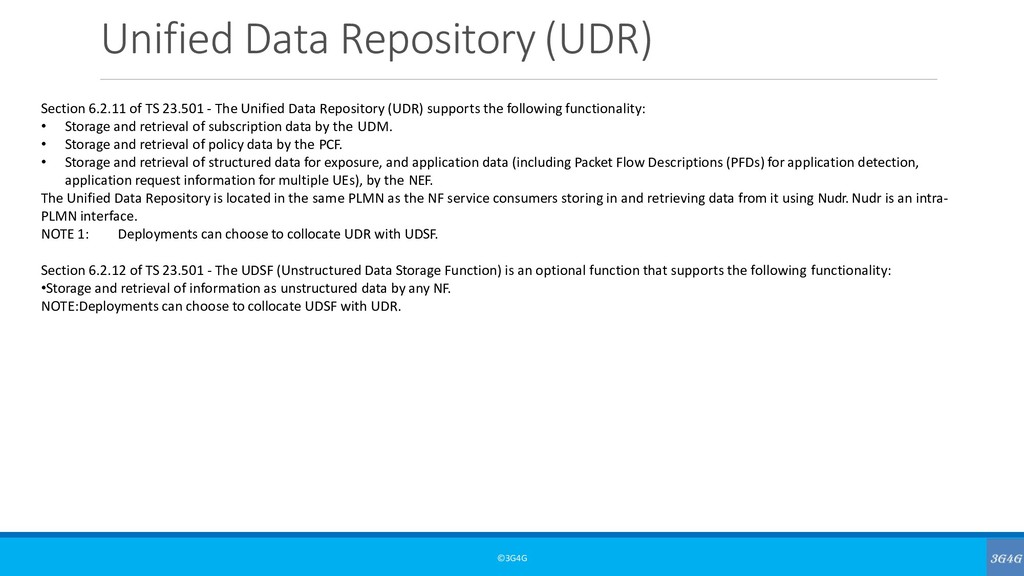
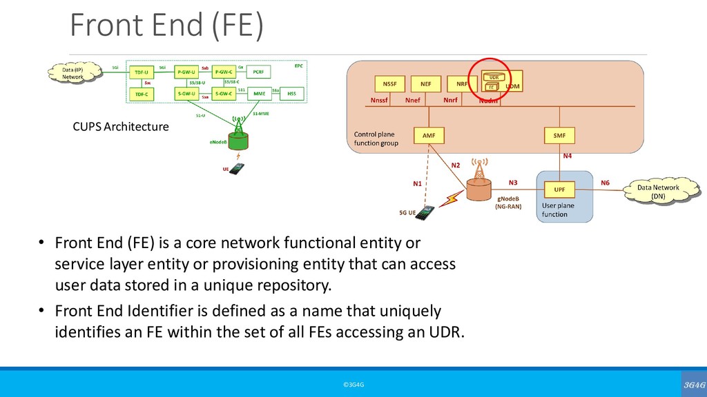
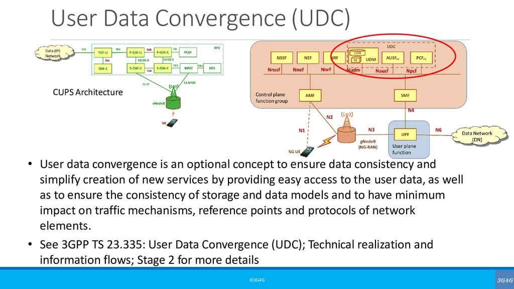
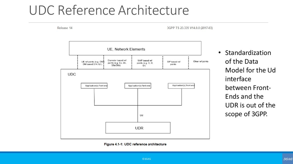
- The Unified Data Repository (UDR) supports the following functionality: • Storage and retrieval of subscription data by the UDM. • Storage and retrieval of policy data by the PCF. • Storage and retrieval of structured data for exposure, and application data (including Packet Flow Descriptions (PFDs) for application detection, application request information for multiple UEs), by the NEF. The Unified Data Repository is located in the same PLMN as the NF service consumers storing in and retrieving data from it using Nudr. Nudr is an intra- PLMN interface. NOTE 1: Deployments can choose to collocate UDR with UDSF. Section 6.2.12 of TS 23.501 - The UDSF (Unstructured Data Storage Function) is an optional function that supports the following functionality: •Storage and retrieval of information as unstructured data by any NF. NOTE:Deployments can choose to collocate UDSF with UDR.
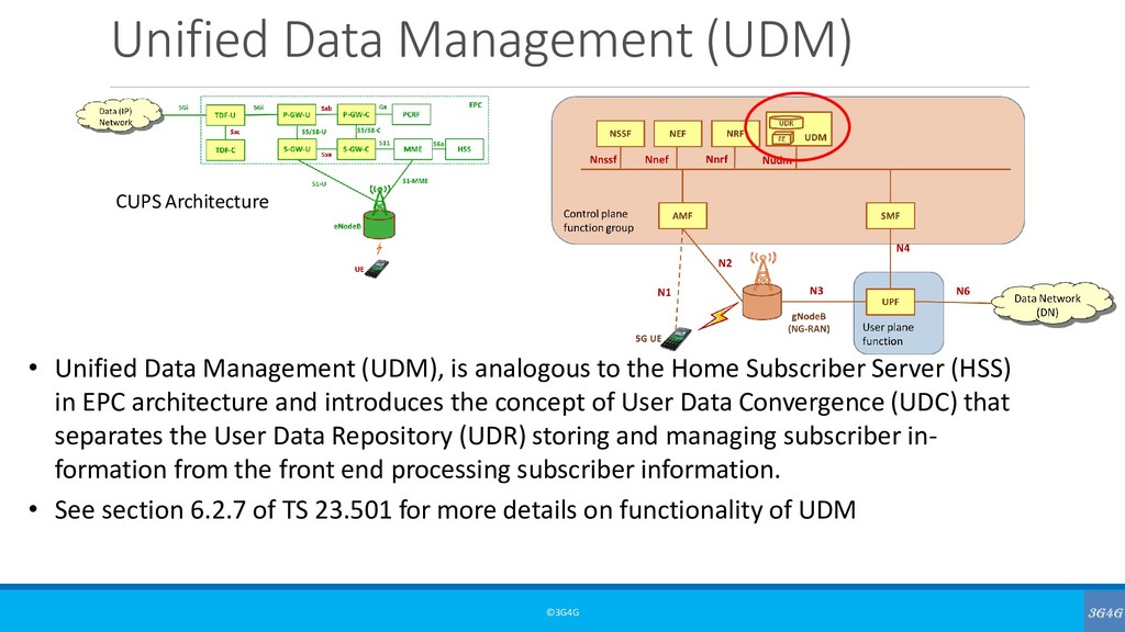
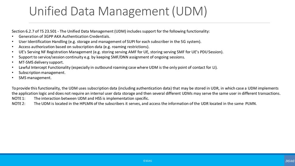
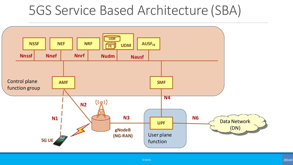
The Unified Data Management (UDM) includes support for the following functionality: • Generation of 3GPP AKA Authentication Credentials. • User Identification Handling (e.g. storage and management of SUPI for each subscriber in the 5G system). • Access authorization based on subscription data (e.g. roaming restrictions). • UE's Serving NF Registration Management (e.g. storing serving AMF for UE, storing serving SMF for UE's PDU Session). • Support to service/session continuity e.g. by keeping SMF/DNN assignment of ongoing sessions. • MT-SMS delivery support. • Lawful Intercept Functionality (especially in outbound roaming case where UDM is the only point of contact for LI). • Subscription management. • SMS management. To provide this functionality, the UDM uses subscription data (including authentication data) that may be stored in UDR, in which case a UDM implements the application logic and does not require an internal user data storage and then several different UDMs may serve the same user in different transactions. NOTE1: NOTE2: The interaction between UDM and HSS is implementation specific. The UDM is located in the HPLMN of the subscribers it serves, and access the information of the UDR located in the same PLMN.
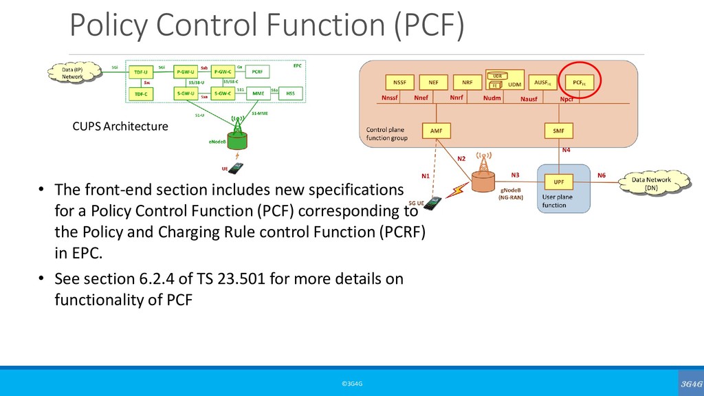
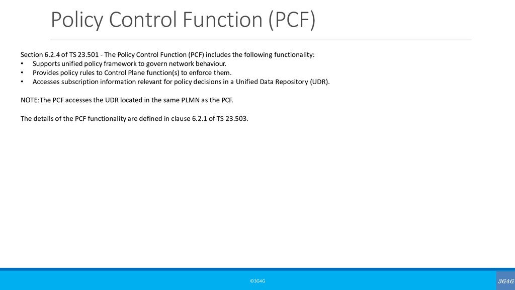
- The Policy Control Function (PCF) includes the following functionality: • Supports unified policy framework to govern network behaviour. • Provides policy rules to Control Plane function(s) to enforce them. • Accesses subscription information relevant for policy decisions in a Unified Data Repository (UDR). NOTE:The PCF accesses the UDR located in the same PLMN as the PCF. The details of the PCF functionality are defined in clause 6.2.1 of TS 23.503.
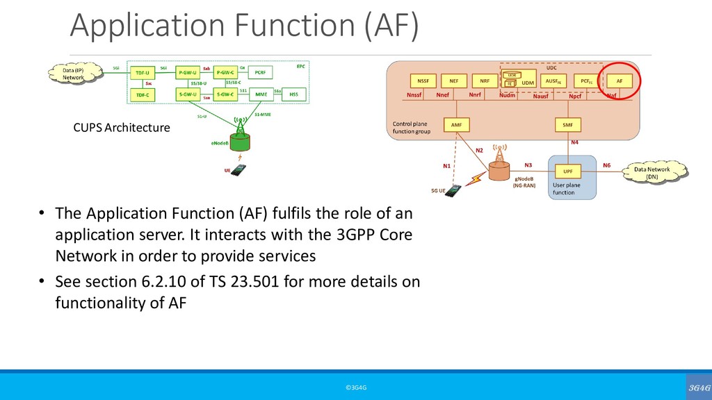
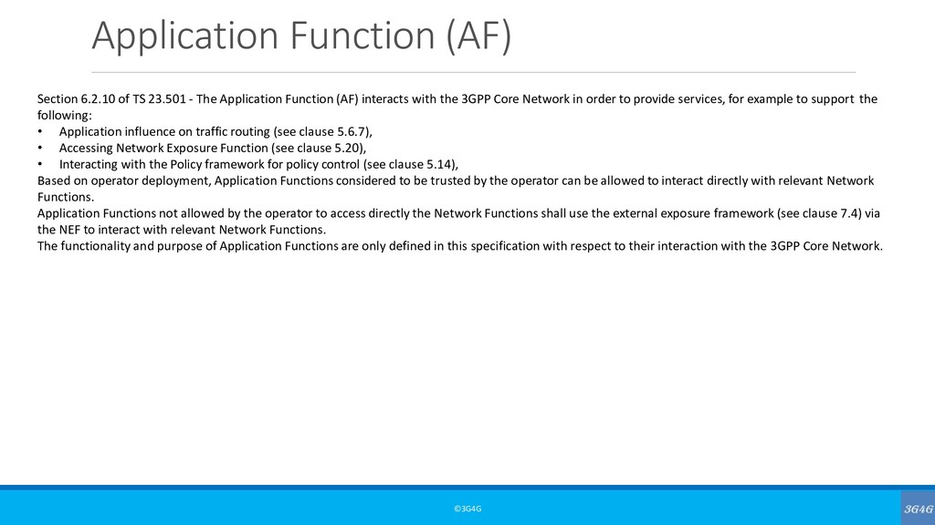
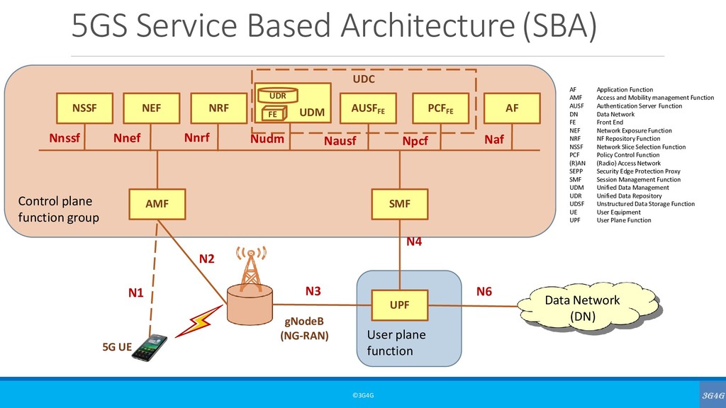
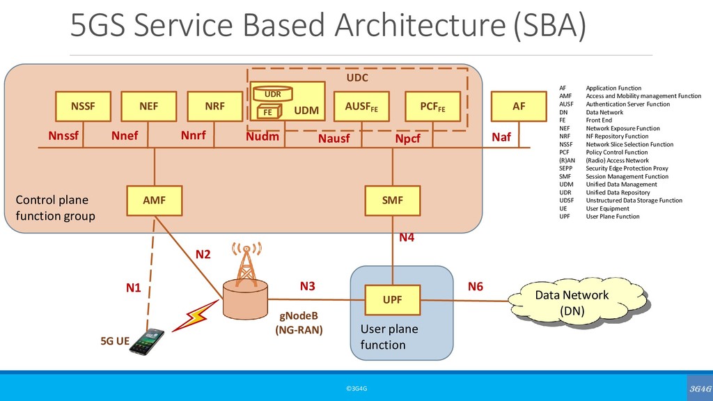
The Application Function (AF) interacts with the 3GPP Core Network in order to provide services, for example to support the following: • Application influence on traffic routing (see clause 5.6.7), • Accessing Network Exposure Function (see clause 5.20), • Interacting with the Policy framework for policy control (see clause 5.14), Based on operator deployment, Application Functions considered to be trusted by the operator can be allowed to interact directly with relevant Network Functions. Application Functions not allowed by the operator to access directly the Network Functions shall use the external exposure framework (see clause 7.4) via the NEF to interact with relevant Network Functions. The functionality and purpose of Application Functions are only defined in this specification with respect to their interaction with the 3GPP Core Network.
5G Resources – 3G4G • 5G – The 3G4G Blog • Rel-15 announcement on Standalone NR – 3GPP, June 2018 • Working towards full 5G in Rel-16 – 3GPP Webinar, July 2018 • Submission of initial 5G description for IMT-2020 – 3GPP, Jan 2018 • NGMN Overview on 5G RAN Functional Decomposition, Feb 2018 • Andy Sutton: 5G Network Architecture, Design and Optimisation – 3G4G Blog, Jan 2018 • 5G NR Resources, Qualcomm • UK5G Innovation Network
Feb. 2015 – This paper lays the foundation on the 5G vision. • 5G Americas: 5G Services & Use Cases, Nov. 2017 – Even though this is US centric, it looks at lots of verticals for the application of 5G • Nokia: Translating 5G use cases into viable business cases, April 2017 • 5G Americas: LTE to 5G – Cellular and Broadband Innovation, August 2017 • GSMA: The 5G era: Age of boundless connectivity and intelligent automation, Feb 2017 • Special Issue on 5G – Journal of ICT Standardization. Articles contributed by 3GPP colleagues, delegates & chairs. • GTI 5G Network Architecture White Paper, Feb 2018 • Deloitte/DCMS: The impacts of mobile broadband and 5G, June 2018 • NTT Docomo: 5G RAN Standardization Trends, Jan 2018
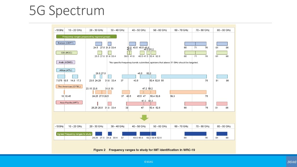
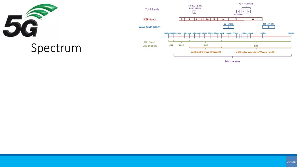
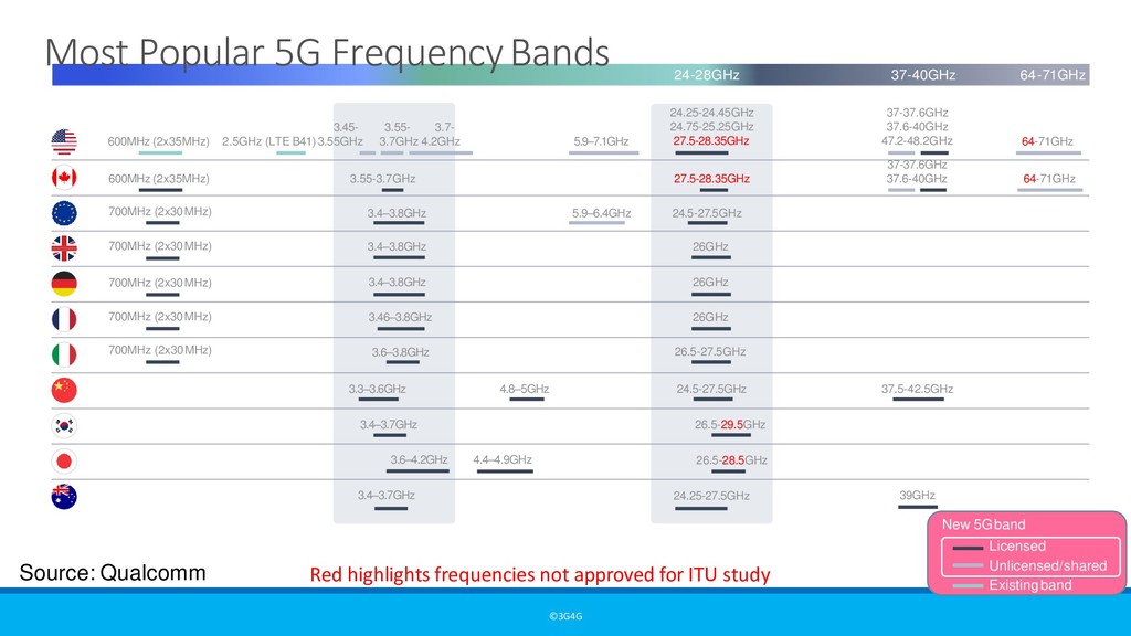
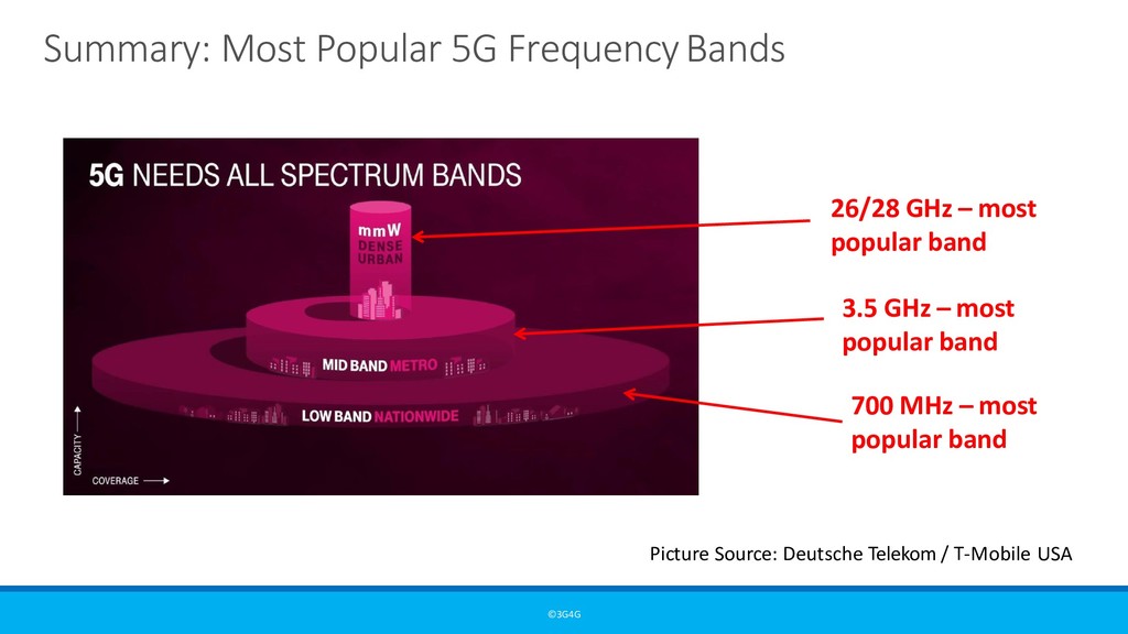
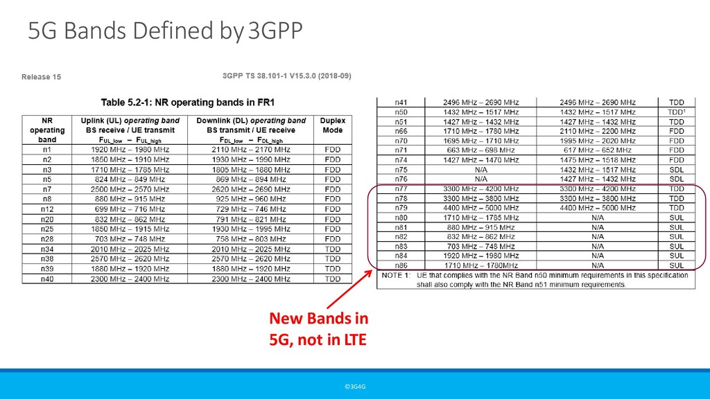
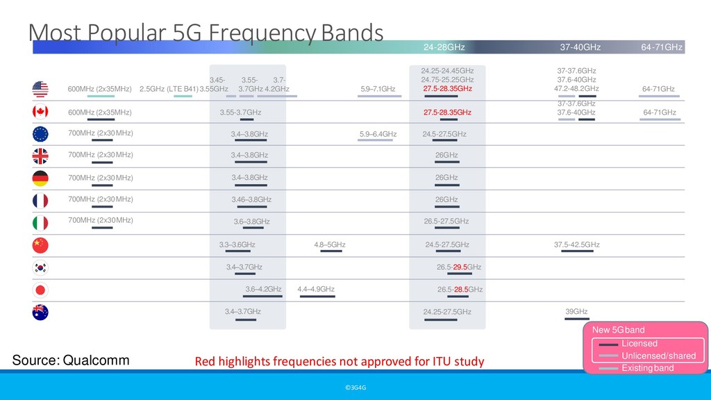
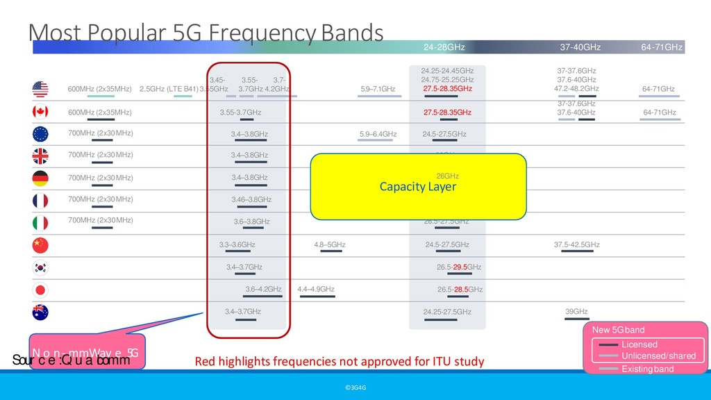
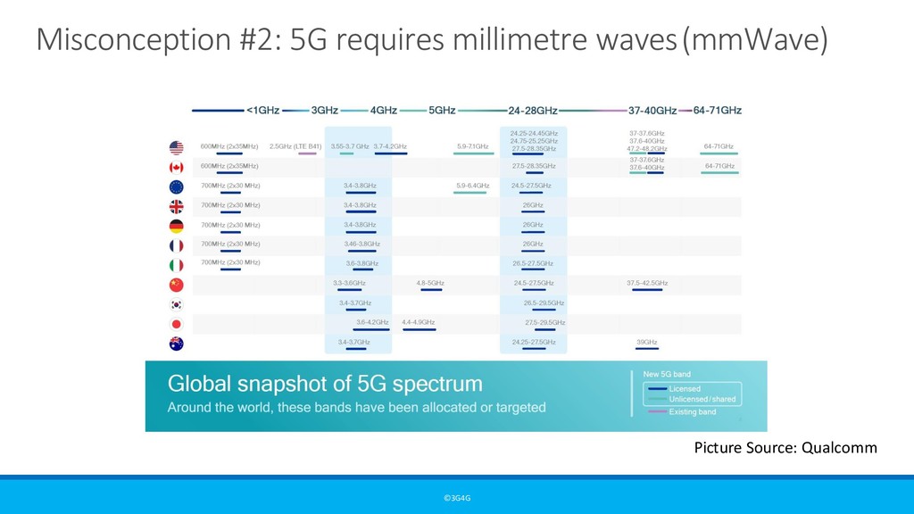
26GHz 3.4–3.8GHz 26GHz 3.46–3.8GHz 26GHz 3.6–3.8GHz 3.3–3.6GHz 4.8–5GHz 24.5-27.5GHz 37.5-42.5GHz 3.4–3.7GHz 26.5-29.5GHz 4.4–4.9GHz 26.5-28.5GHz 3.4–3.7GHz 39GHz 3.6–4.2GHz 64-71GHz 37-37.6GHz 37.6-40GHz 47.2-48.2GHz 5.9–6.4GHz 5.9–7.1GHz 600MHz (2x35MHz) 27.5-28.35GHz 64-71GHz 37-37.6GHz 37.6-40GHz 24.25-27.5GHz 26.5-27.5GHz 3.55- 3.7- 3.7GHz 4.2GHz 3.55-3.7GHz 700MHz (2x30MHz) 700MHz (2x30MHz) 700MHz (2x30MHz) 700MHz (2x30MHz) Most Popular 5G FrequencyBands <1GHz 3GHz 4GHz 5GHz 24-28GHz 37-40GHz 64-71GHz 3.45- 2.5GHz (LTE B41)3.55GHz Licensed Unlicensed/shared Existing band New 5Gband Red highlights frequencies not approved for ITU study Sour N c o e n : - Q m u m a W l c a o v m e m 5 G C3 . o4 – v3 e. 8 G raH z geLayer
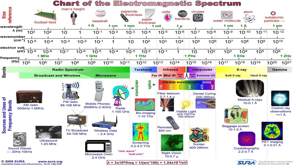
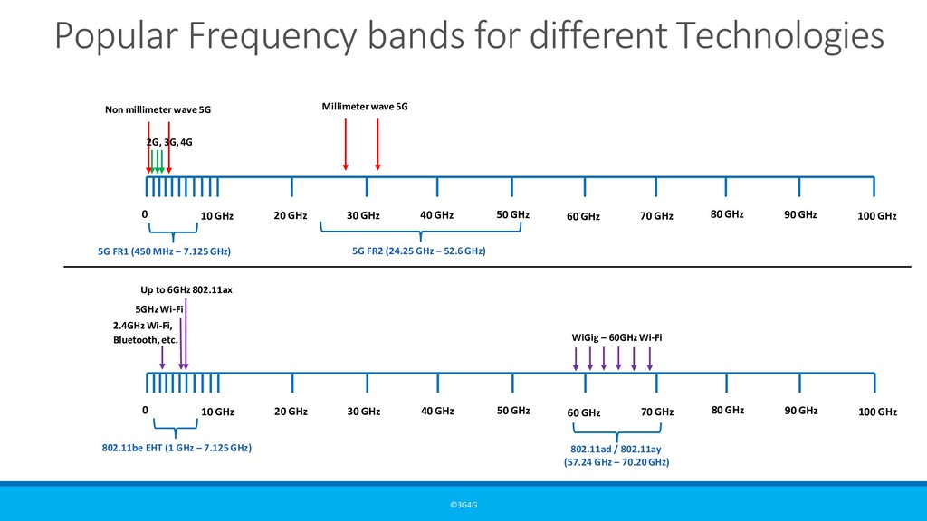
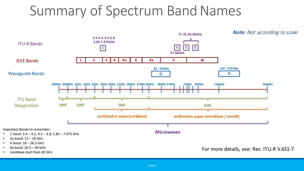
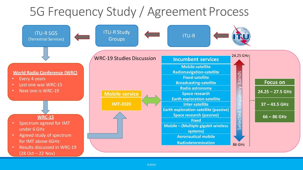
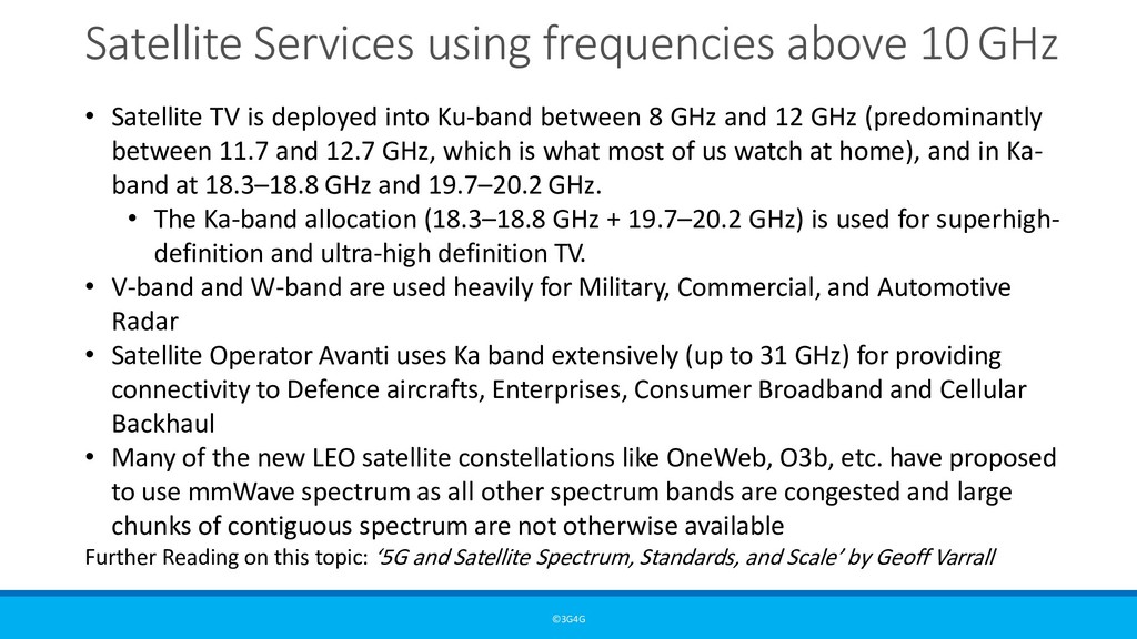
is deployed into Ku-band between 8 GHz and 12 GHz (predominantly between 11.7 and 12.7 GHz, which is what most of us watch at home), and in Ka- band at 18.3–18.8 GHz and 19.7–20.2 GHz. • The Ka-band allocation (18.3–18.8 GHz + 19.7–20.2 GHz) is used for superhigh- definition and ultra-high definition TV. • V-band and W-band are used heavily for Military, Commercial, and Automotive Radar • Satellite Operator Avanti uses Ka band extensively (up to 31 GHz) for providing connectivity to Defence aircrafts, Enterprises, Consumer Broadband and Cellular Backhaul • Many of the new LEO satellite constellations like OneWeb, O3b, etc. have proposed to use mmWave spectrum as all other spectrum bands are congested and large chunks of contiguous spectrum are not otherwise available Further Reading on this topic: ‘5G and Satellite Spectrum, Standards, and Scale’ by Geoff Varrall
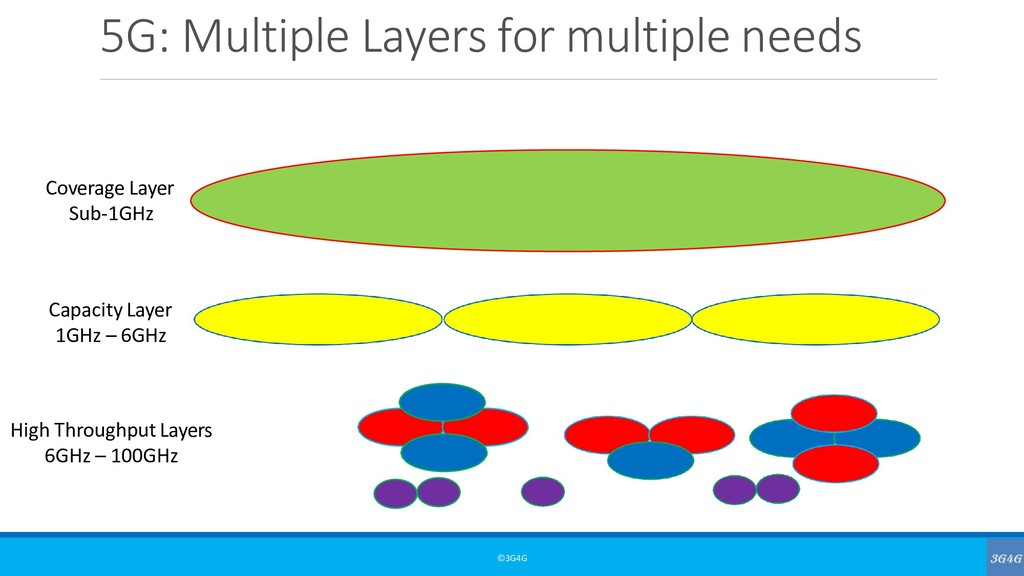
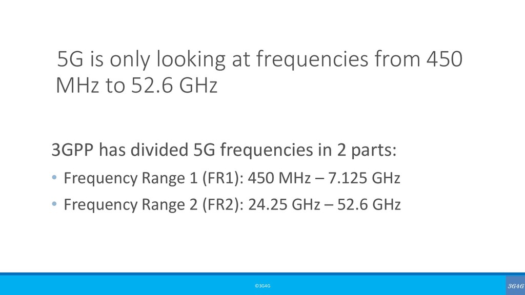
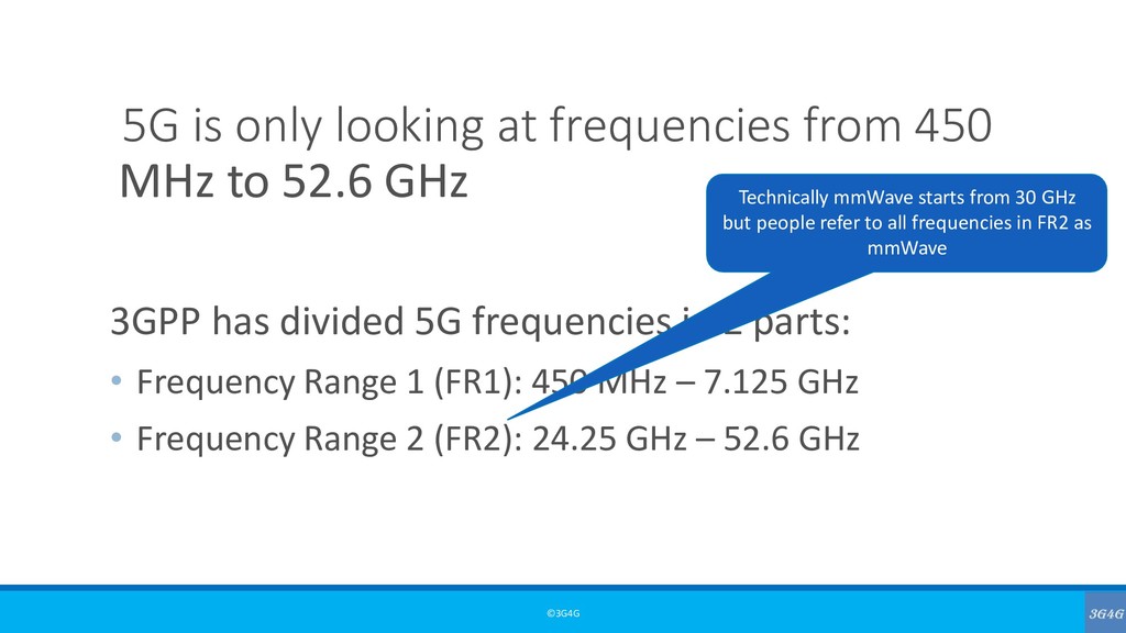
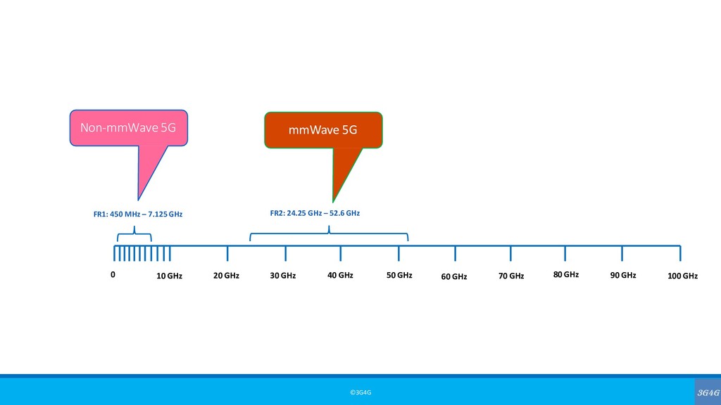
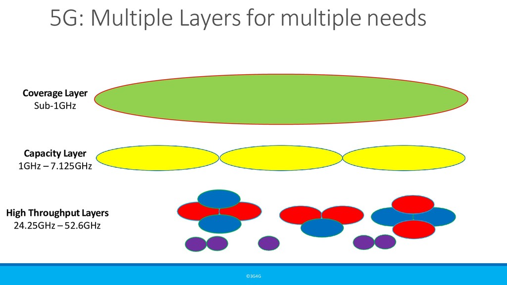
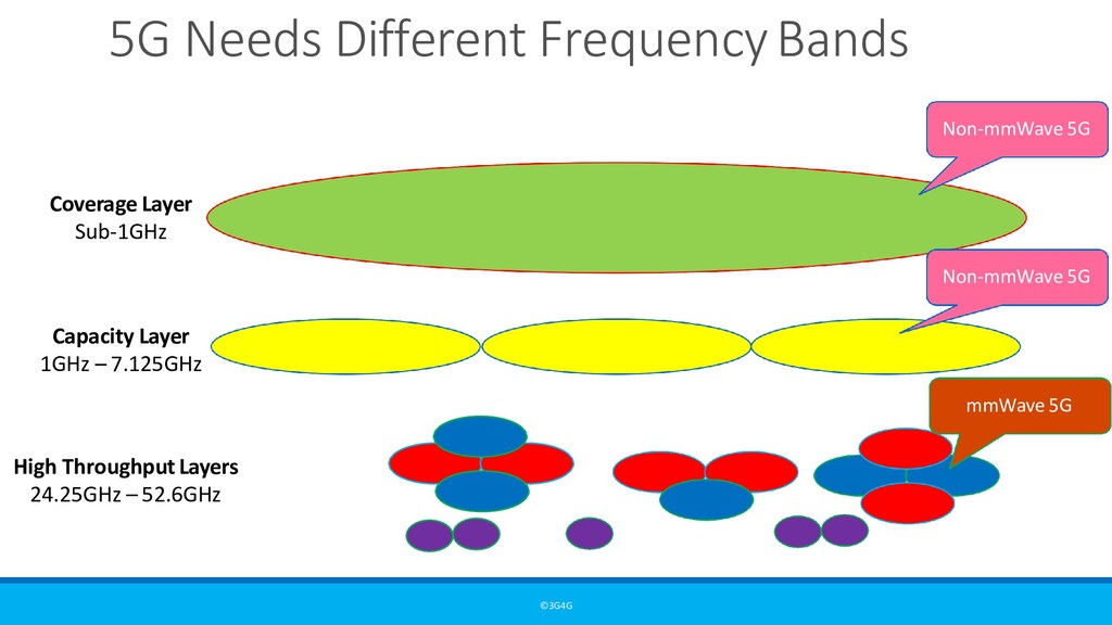
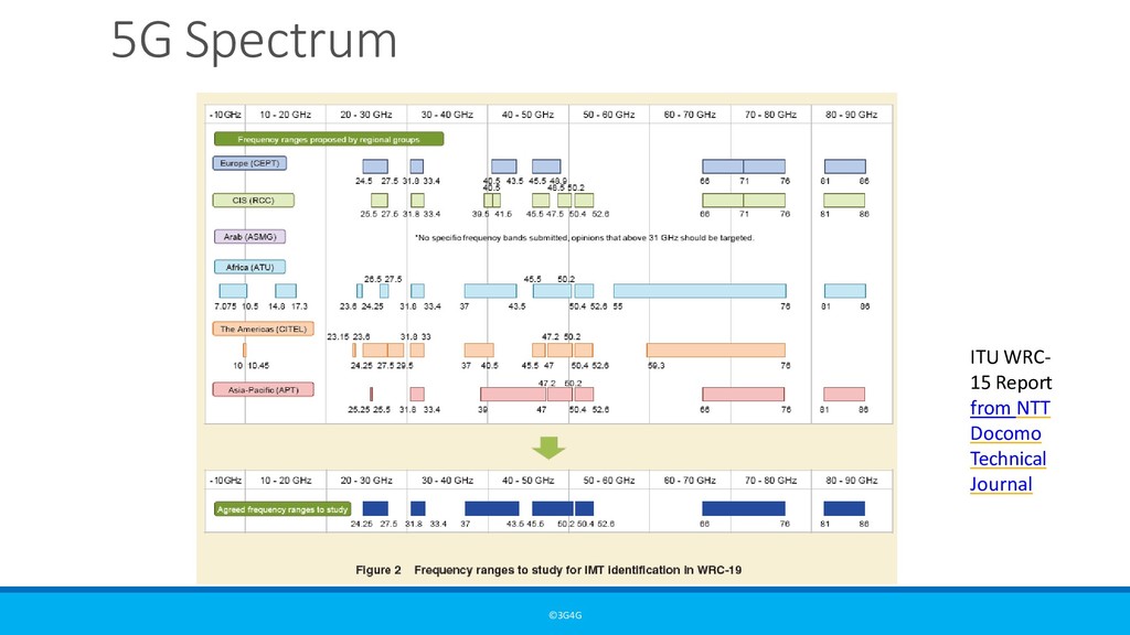
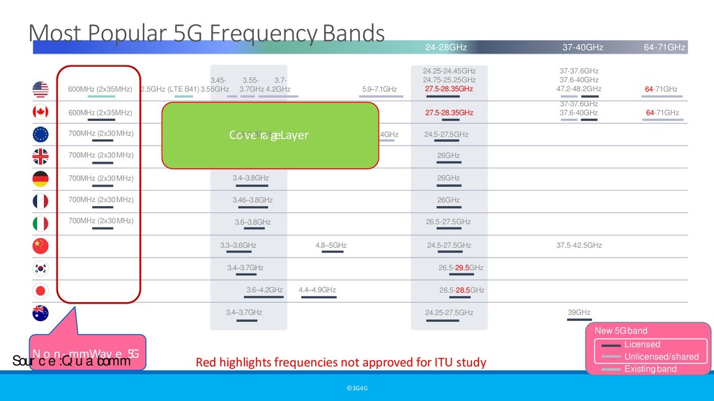
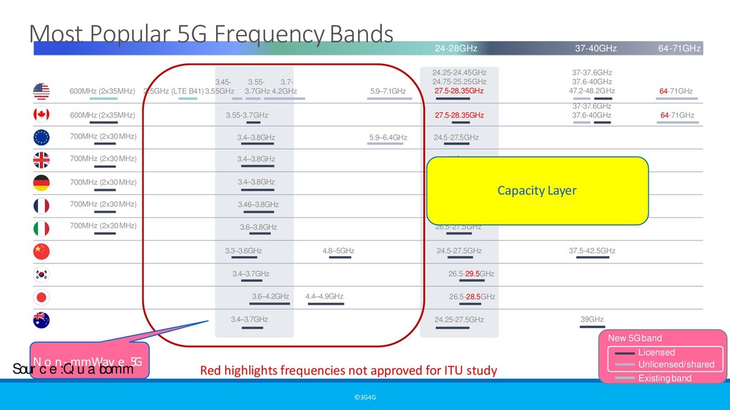
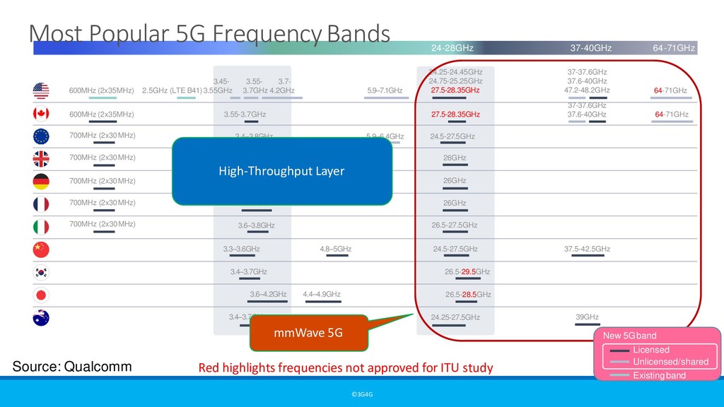
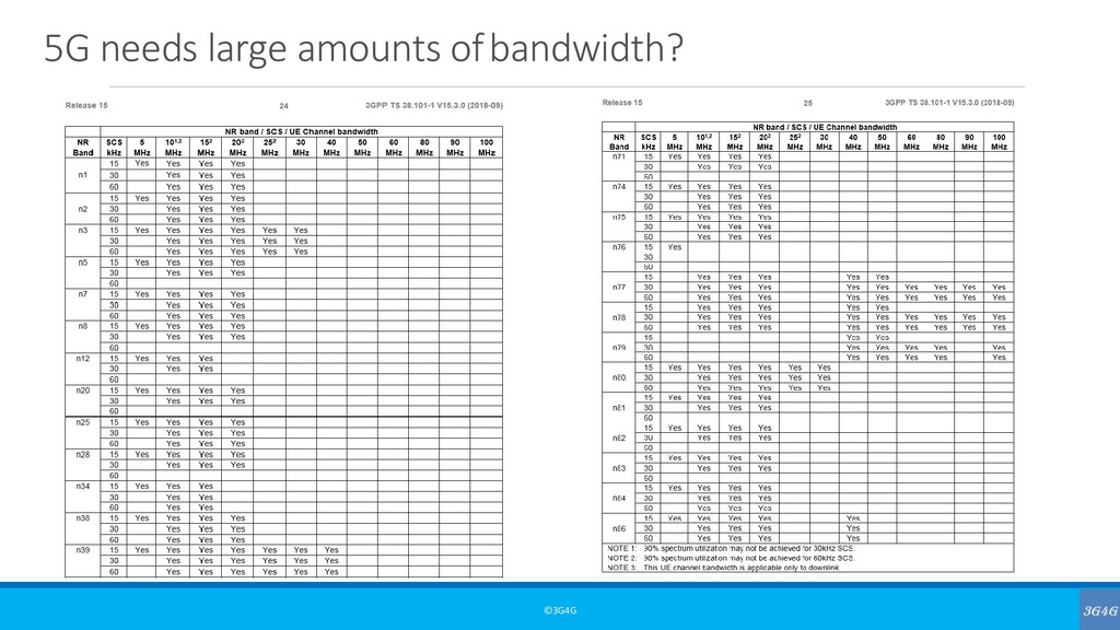
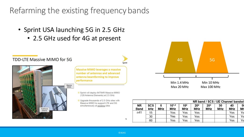
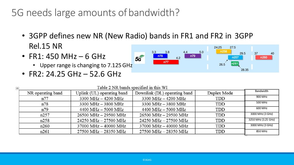
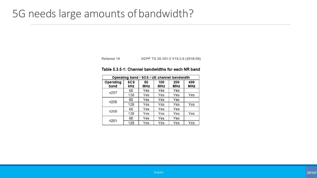
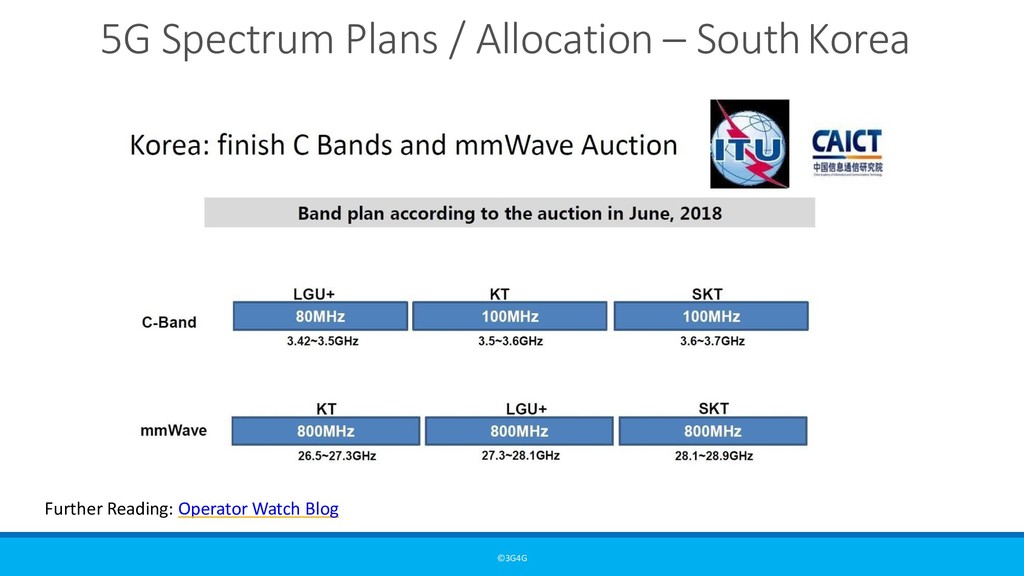
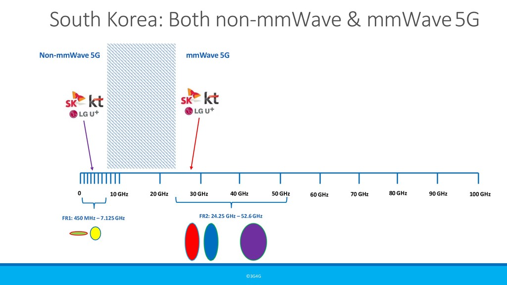
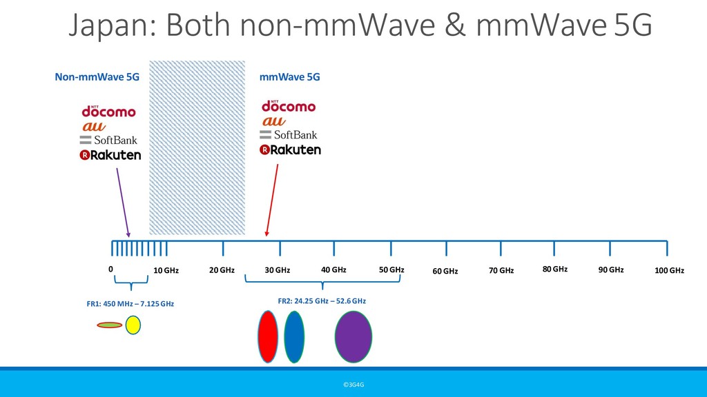
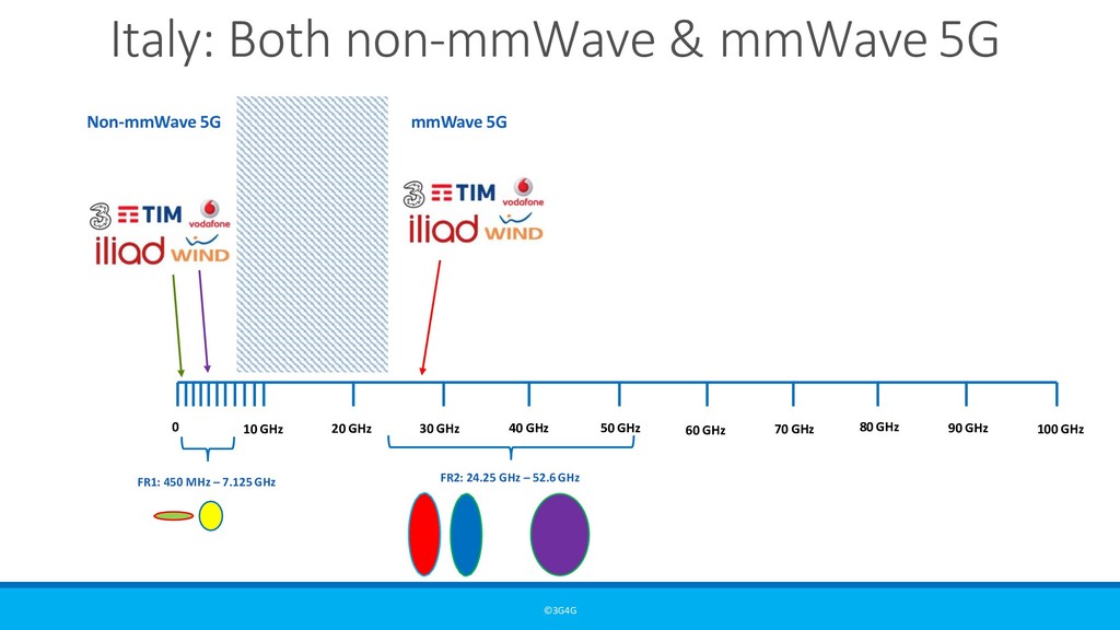
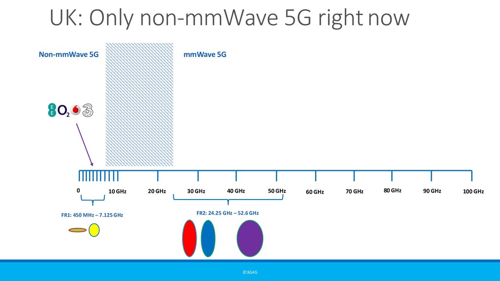
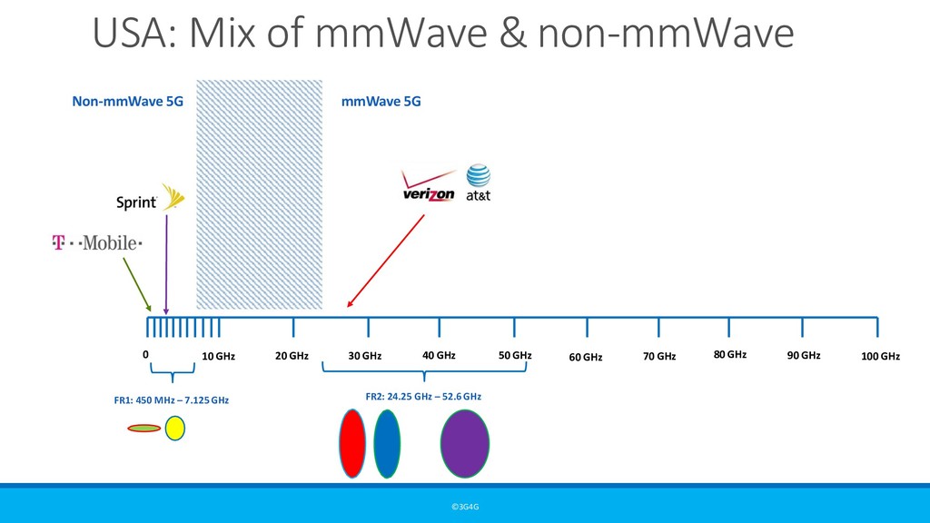
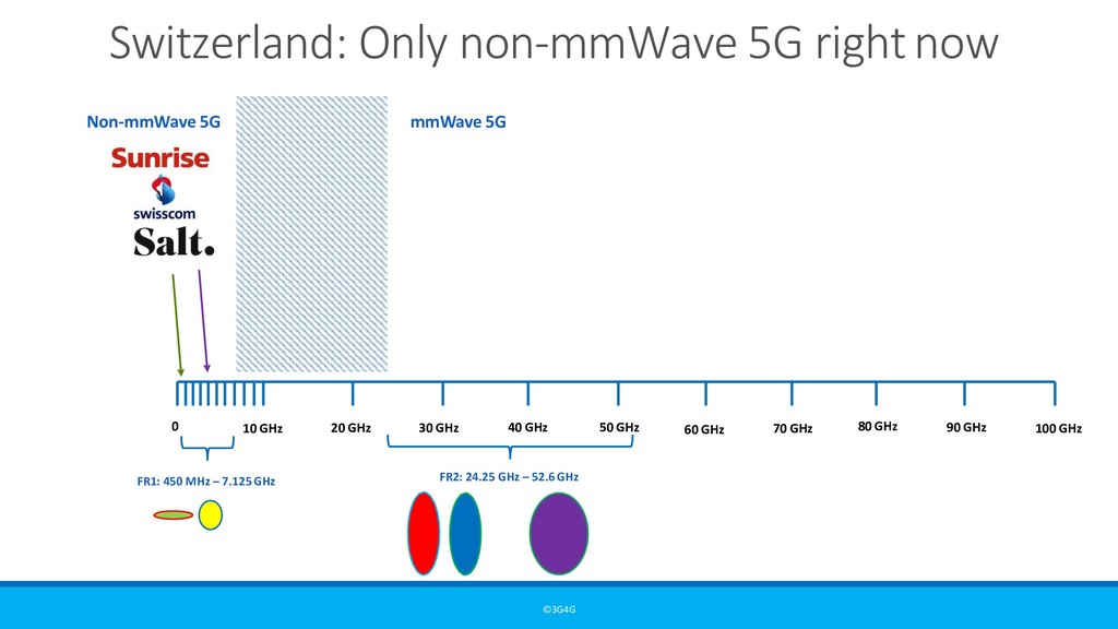
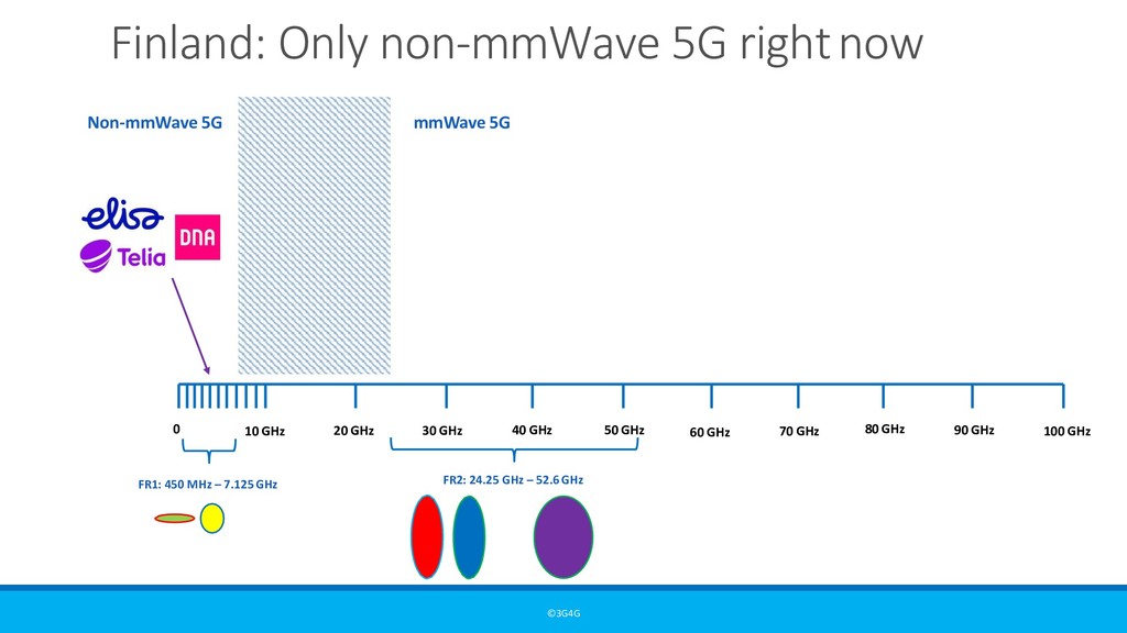
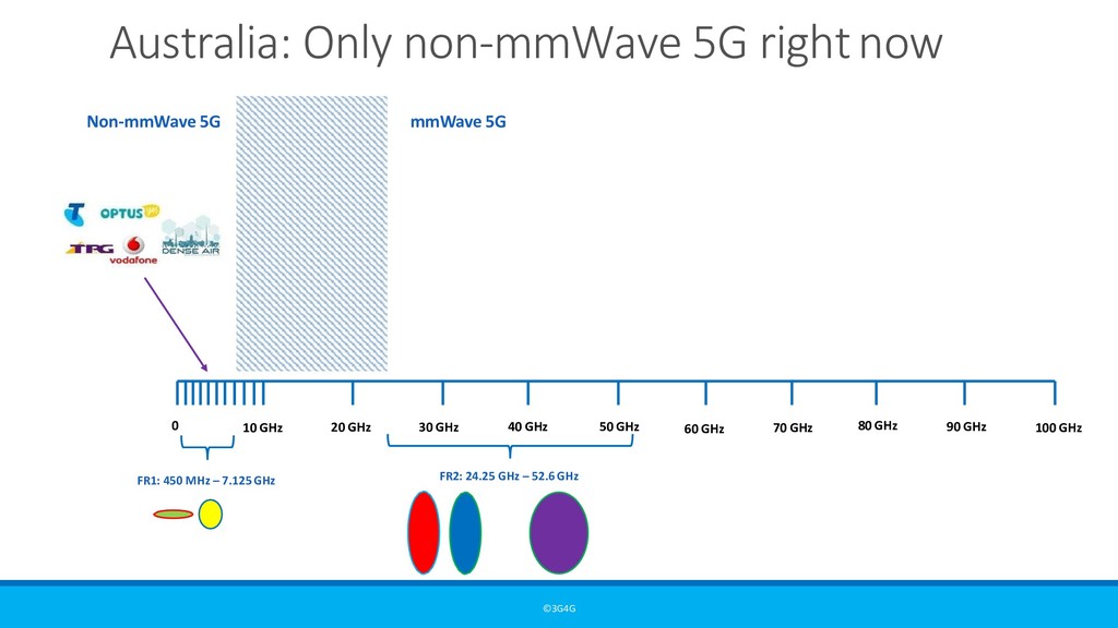
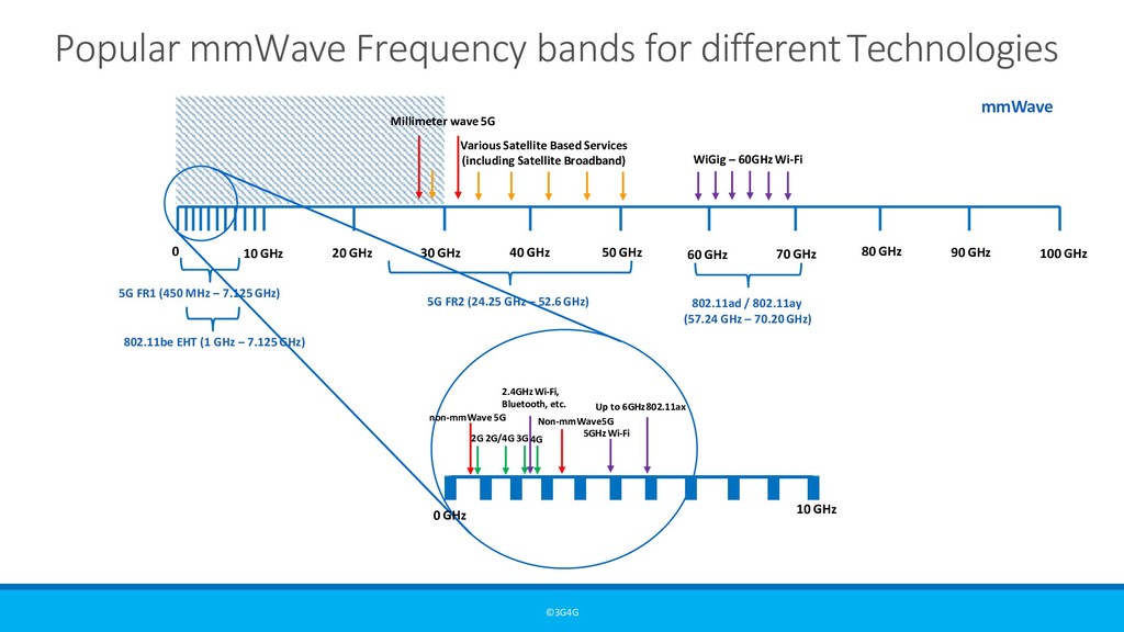
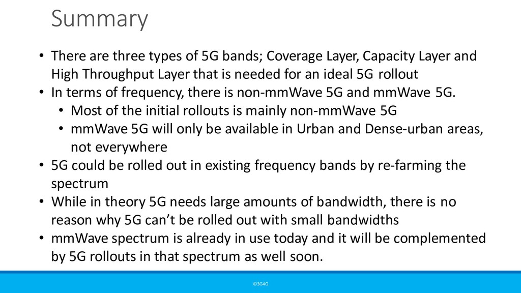
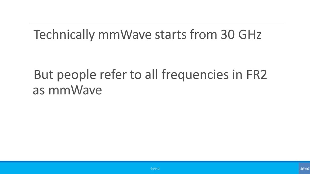
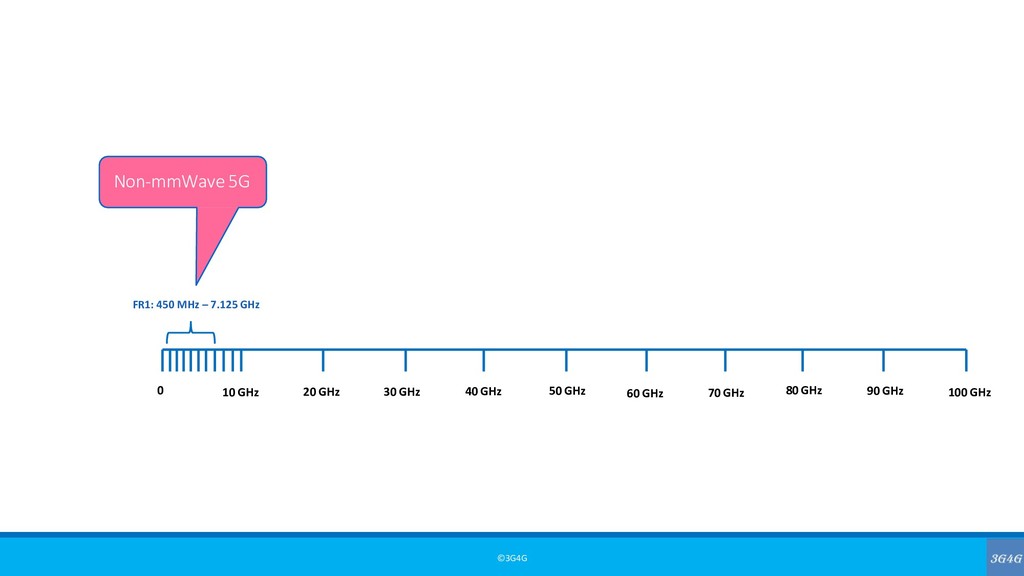
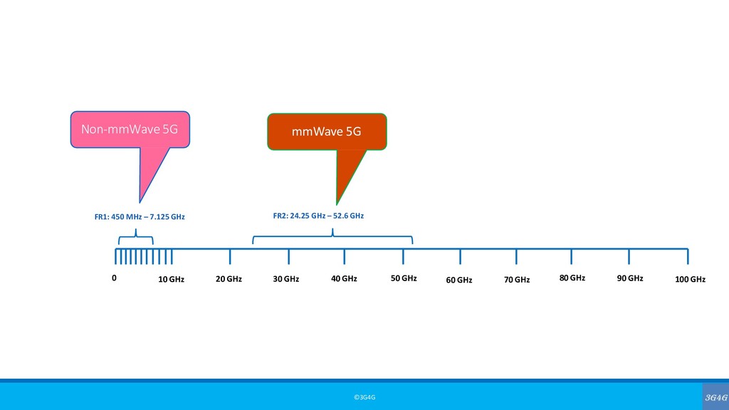
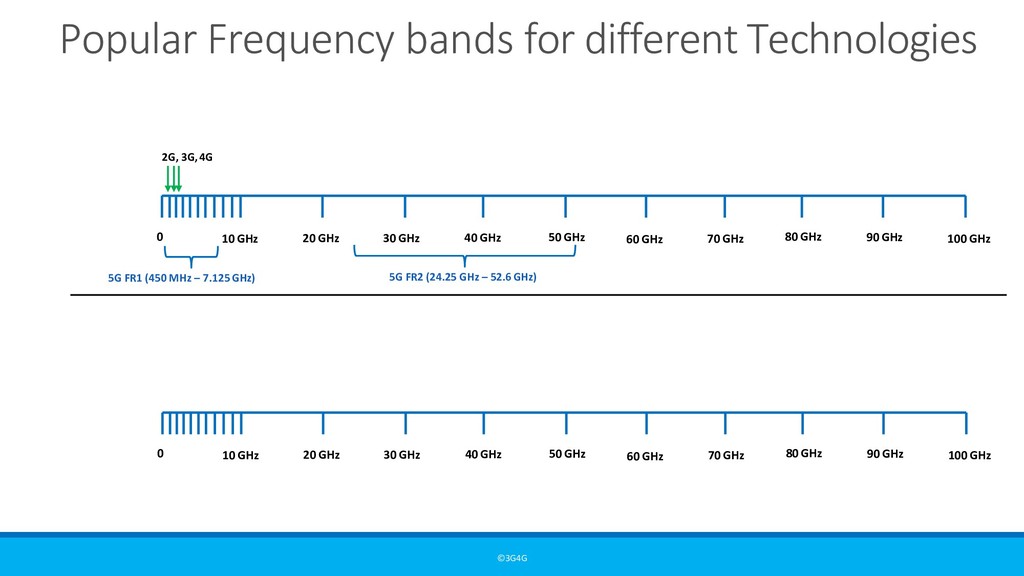
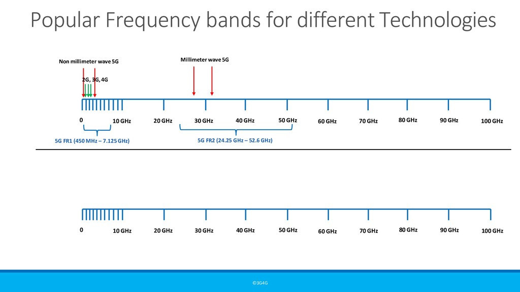
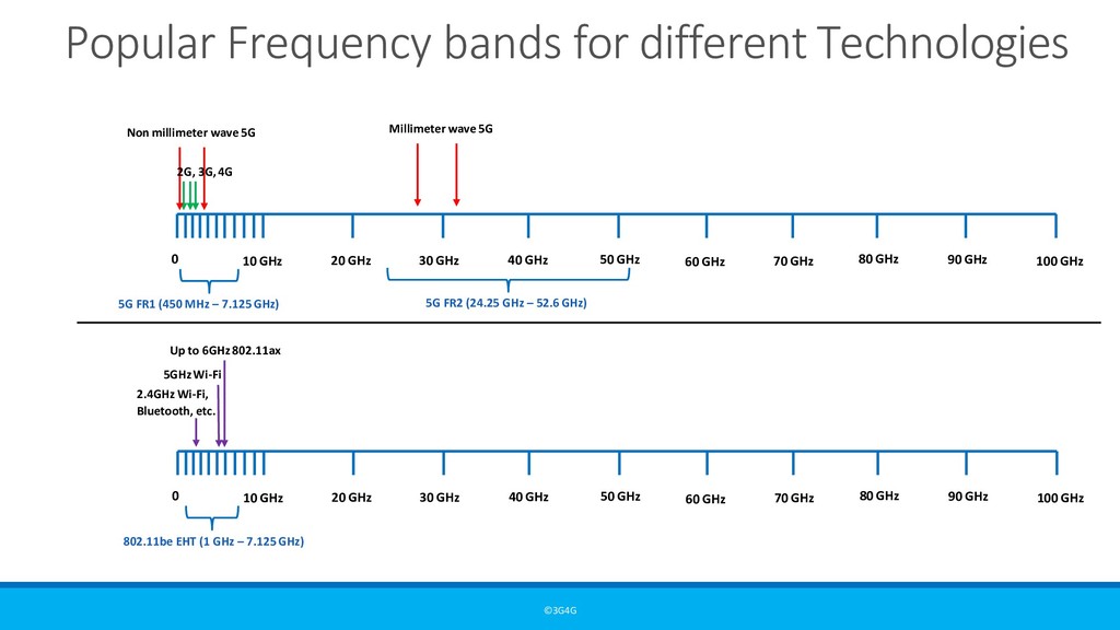
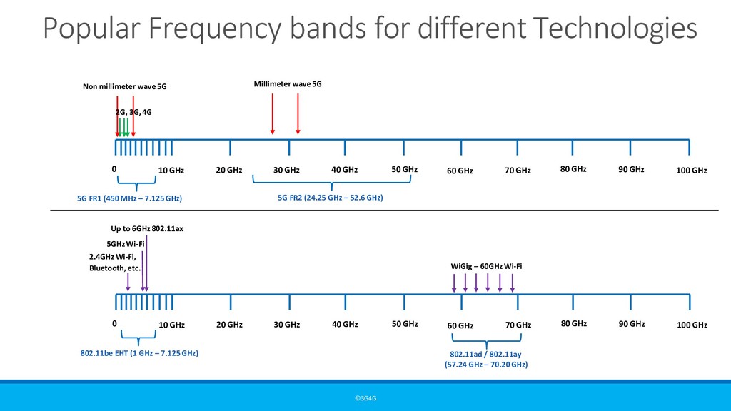
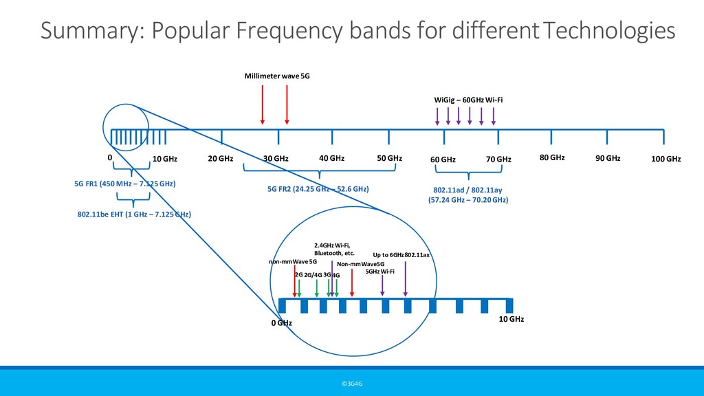
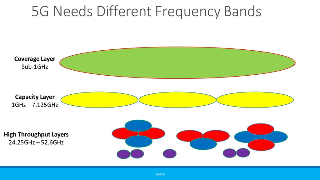
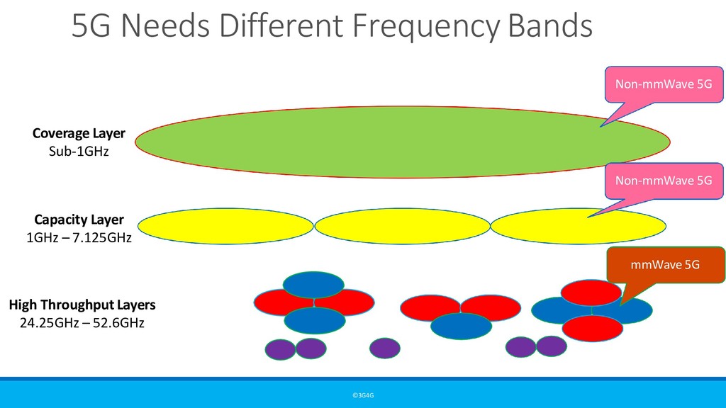
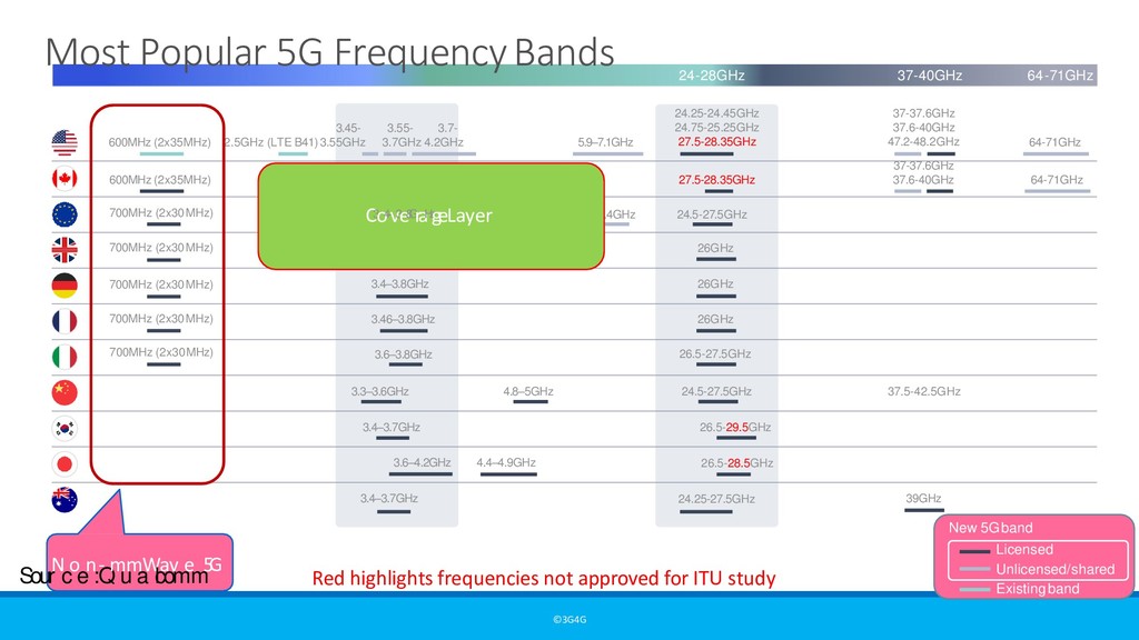
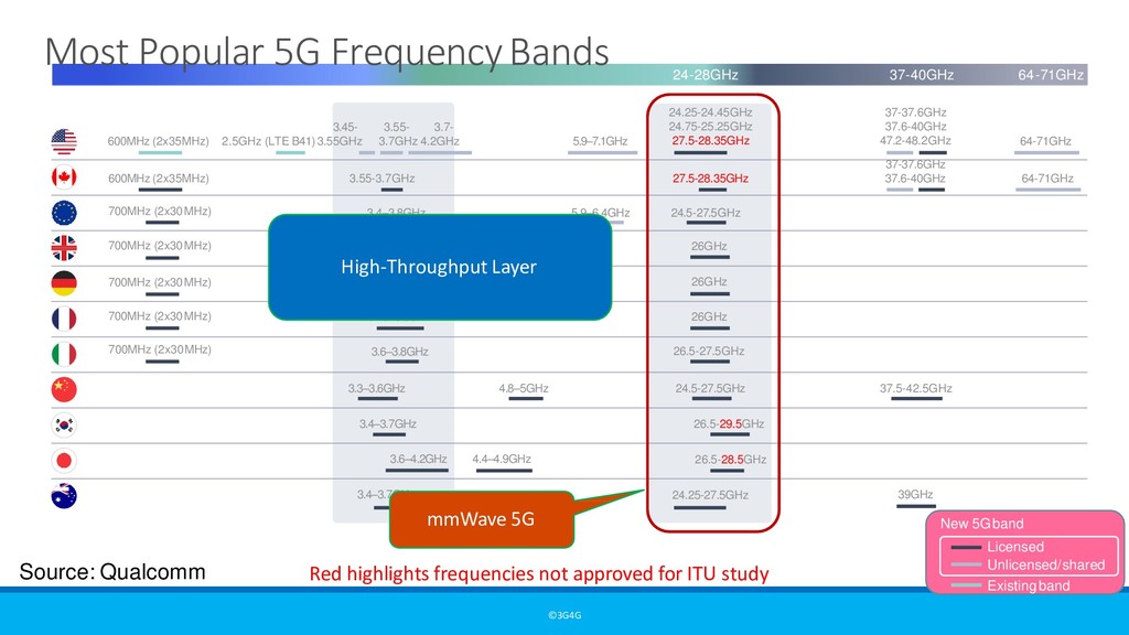
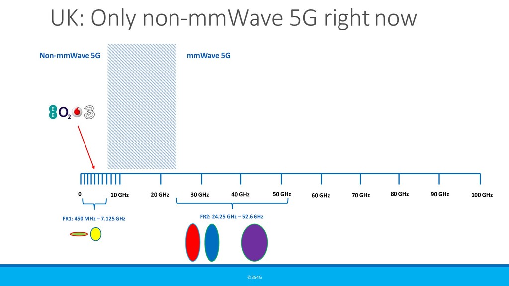
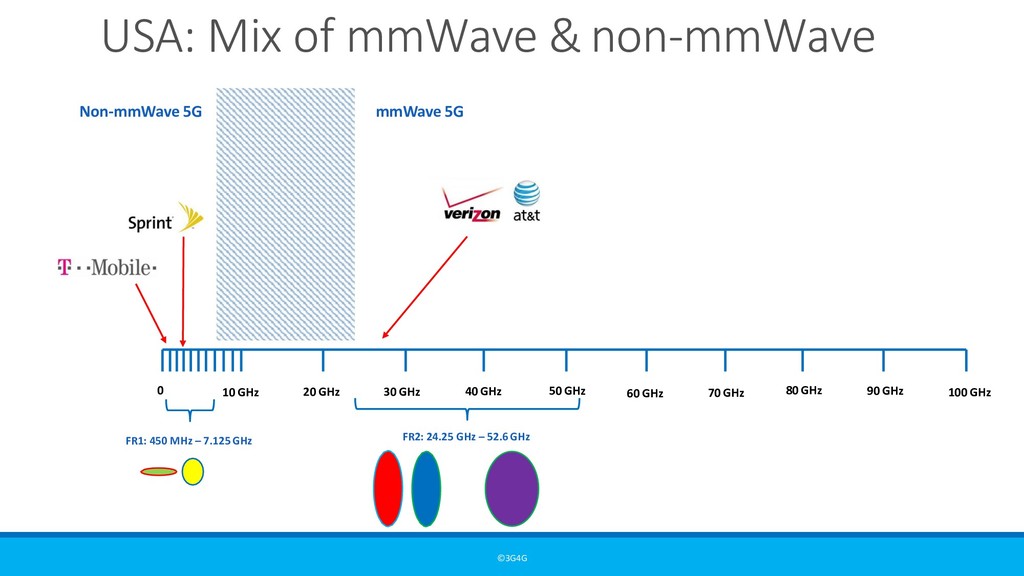
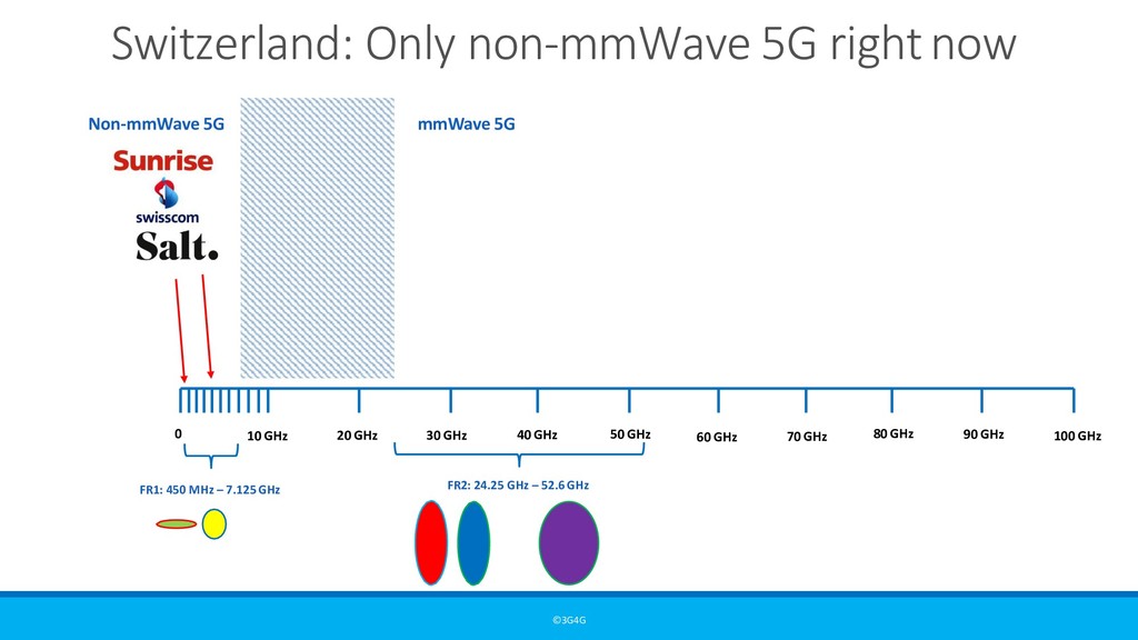
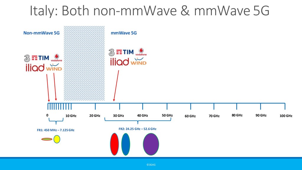
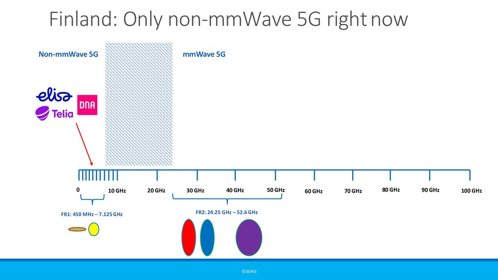
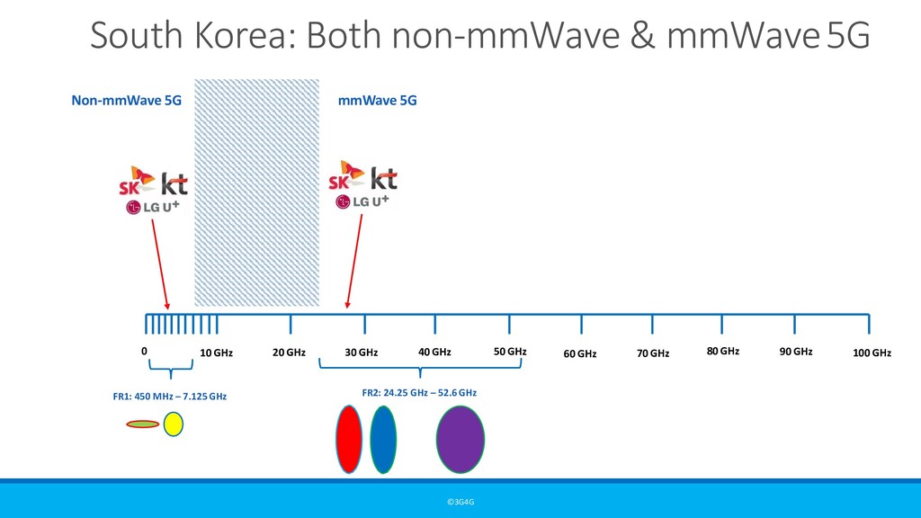
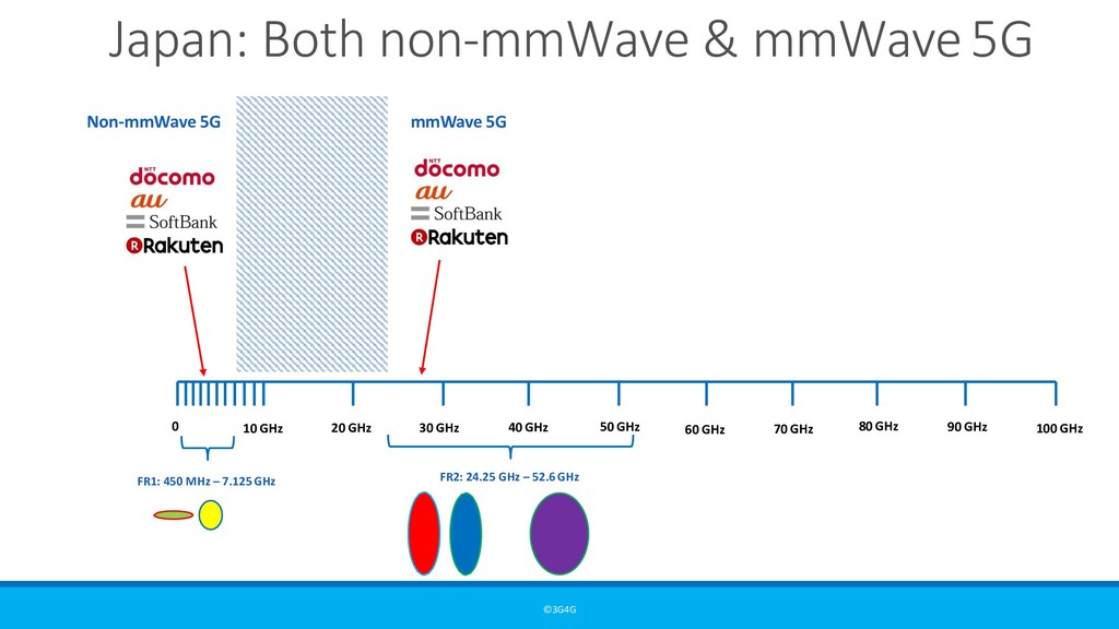
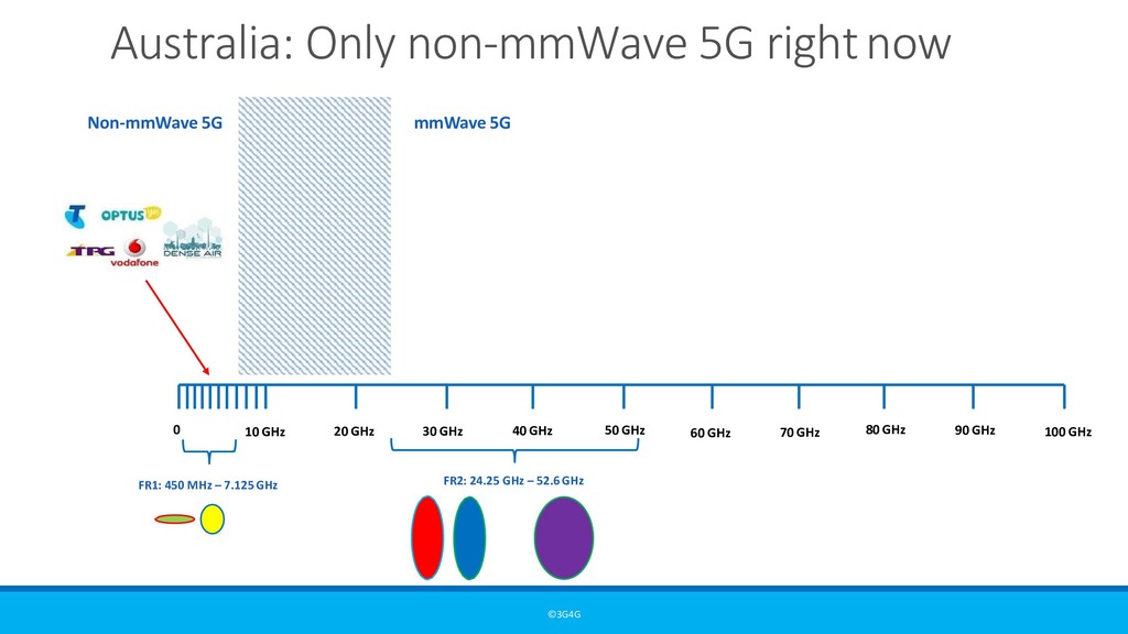
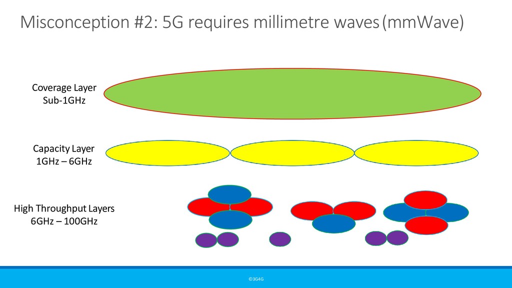
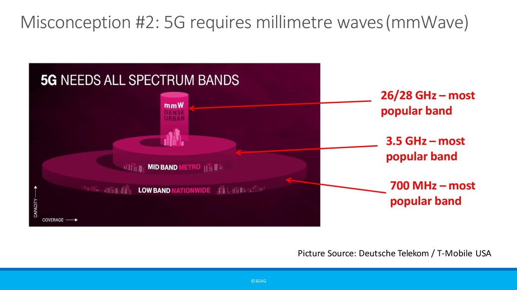
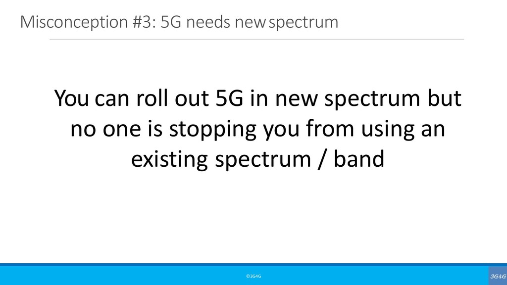
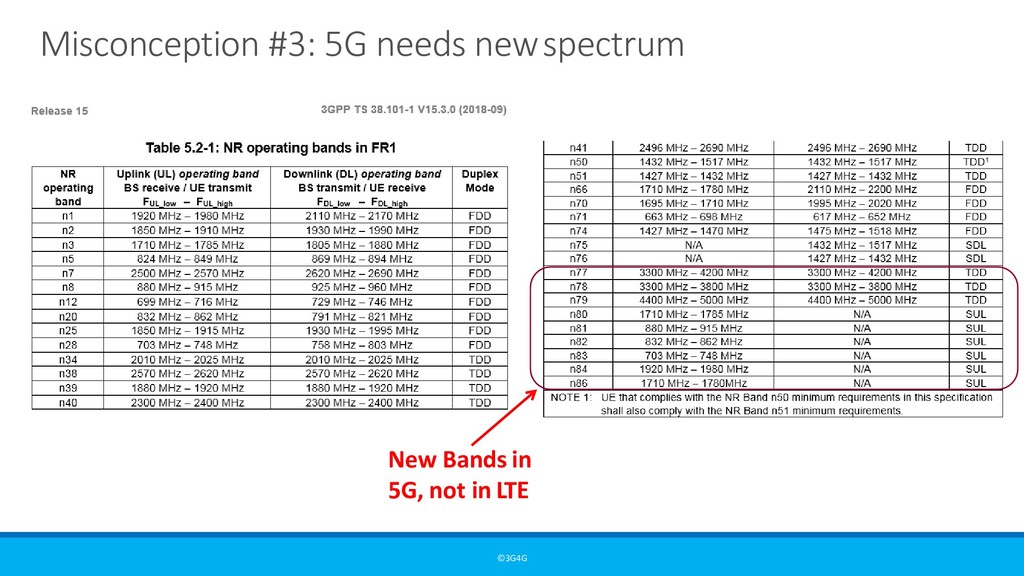
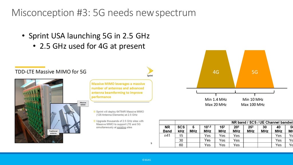
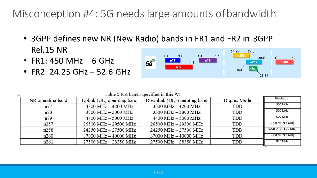
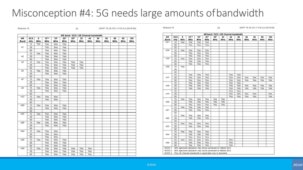
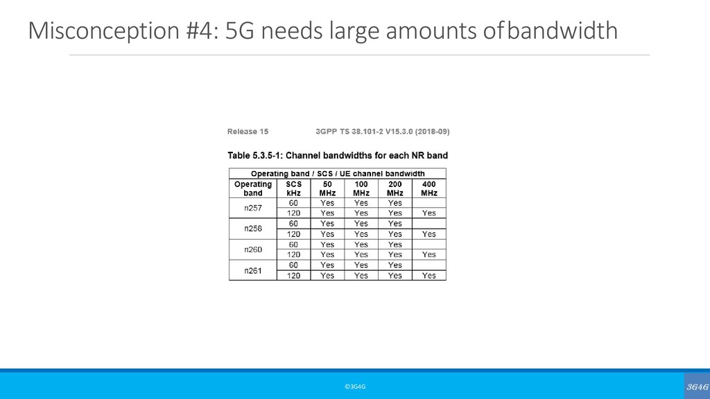
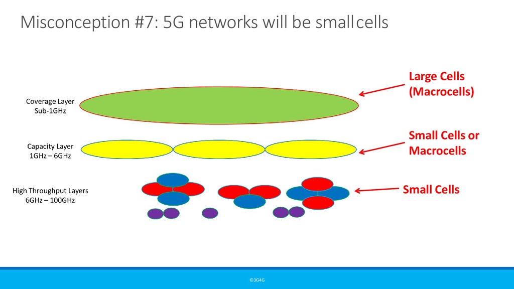
Coverage Layer, Capacity Layer and High Throughput Layer that is needed for an ideal 5G rollout • In terms of frequency, there is non-mmWave 5G and mmWave 5G. • Most of the initial rollouts is mainly non-mmWave 5G • mmWave 5G will only be available in Urban and Dense-urban areas, not everywhere • 5G could be rolled out in existing frequency bands by re-farming the spectrum • While in theory 5G needs large amounts of bandwidth, there is no reason why 5G can’t be rolled out with small bandwidths • mmWave spectrum is already in use today and it will be complemented by 5G rollouts in that spectrum as well soon.
26GHz 3.4–3.8GHz 26GHz 3.46–3.8GHz 26GHz 3.6–3.8GHz 3.3–3.6GHz 4.8–5GHz 24.5-27.5GHz 37.5-42.5GHz 3.4–3.7GHz 26.5-29.5GHz 4.4–4.9GHz 26.5-28.5GHz 3.4–3.7GHz 39GHz 3.6–4.2GHz 64-71GHz 37-37.6GHz 37.6-40GHz 47.2-48.2GHz 5.9–6.4GHz 5.9–7.1GHz 600MHz (2x35MHz) 27.5-28.35GHz 64-71GHz 37-37.6GHz 37.6-40GHz 24.25-27.5GHz 26.5-27.5GHz 3.55- 3.7- 3.7GHz 4.2GHz 3.55-3.7GHz 700MHz (2x30MHz) 700MHz (2x30MHz) 700MHz (2x30MHz) 700MHz (2x30MHz) Most Popular 5G FrequencyBands <1GHz 3GHz 4GHz 5GHz 24-28GHz 37-40GHz 64-71GHz 3.45- 2.5GHz (LTE B41)3.55GHz Licensed Unlicensed/shared Existing band New 5Gband Red highlights frequencies not approved for ITU study Sour N c o e n : - Q m u m a W l c a o v m e m 5 G C3 . o4 – v3 e. 8 G raH z geLayer
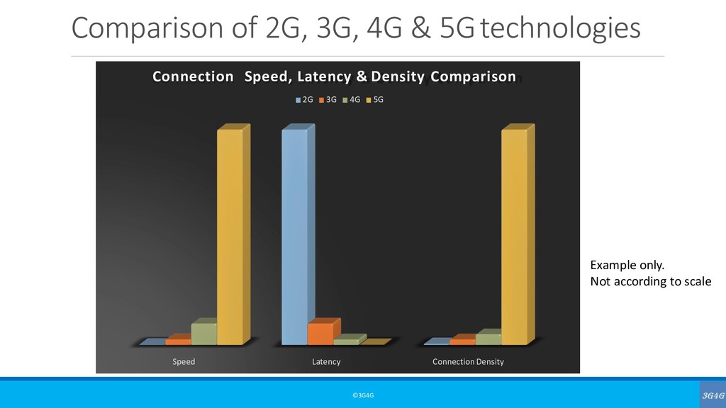
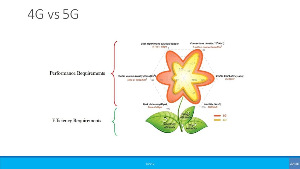
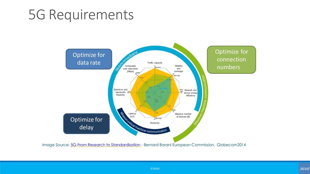
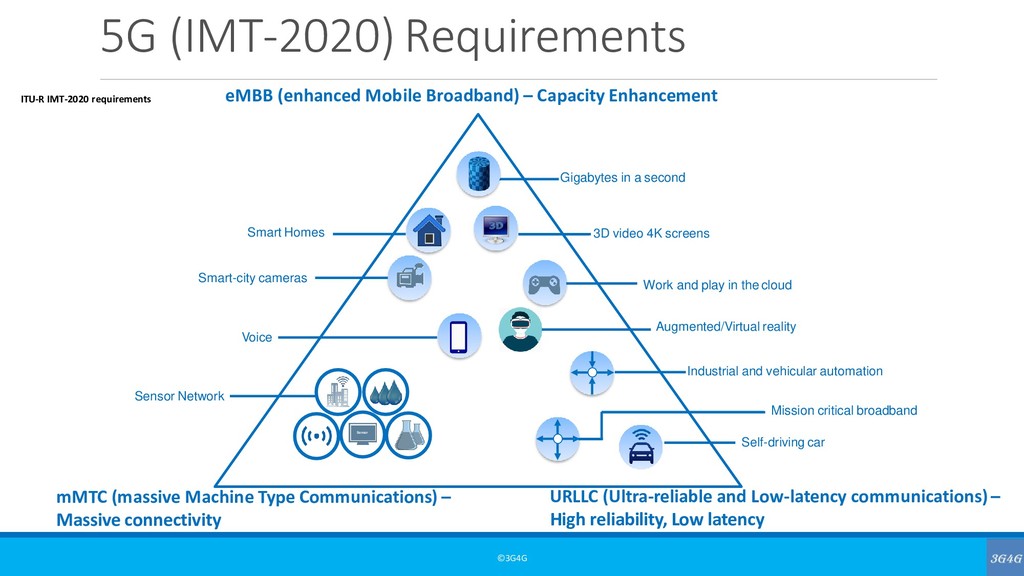
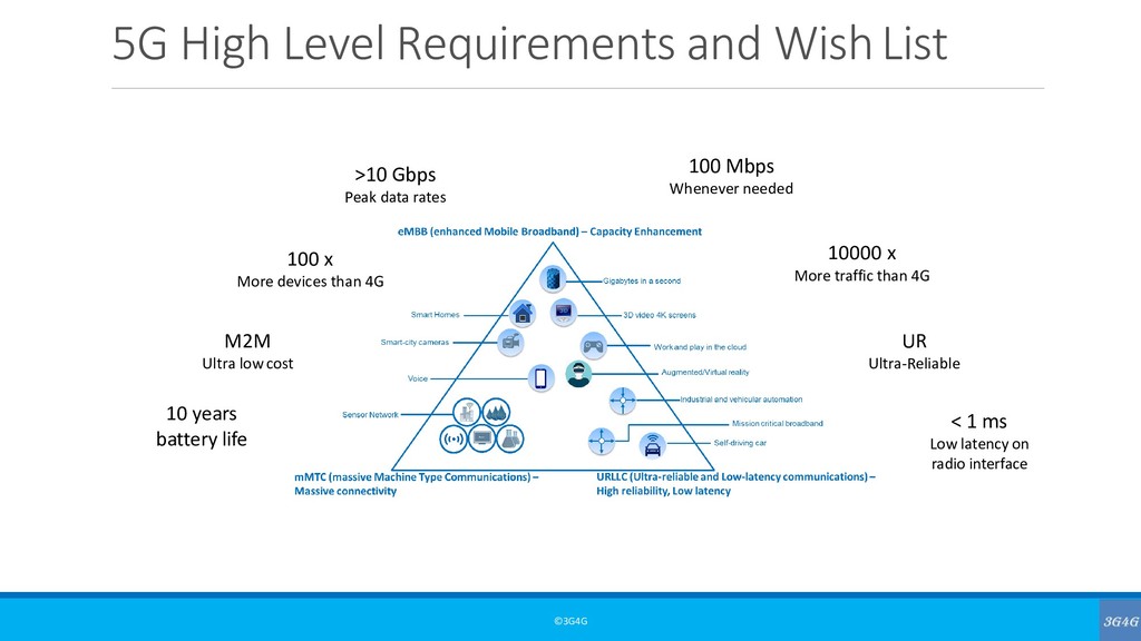
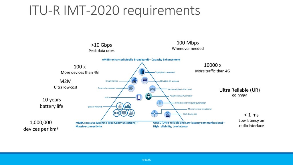
low cost 100 x More devices than 4G >10 Gbps Peak data rates 100 Mbps Whenever needed 10000 x More traffic than 4G Ultra Reliable (UR) 99.999% < 1 ms Low latency on radio interface 1,000,000 devices per km2
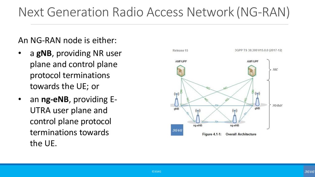
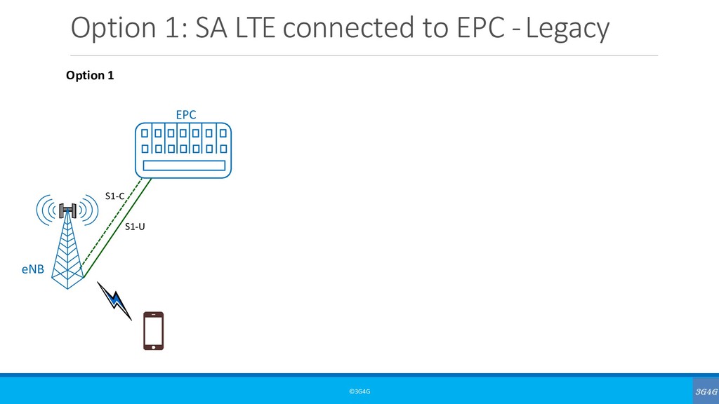
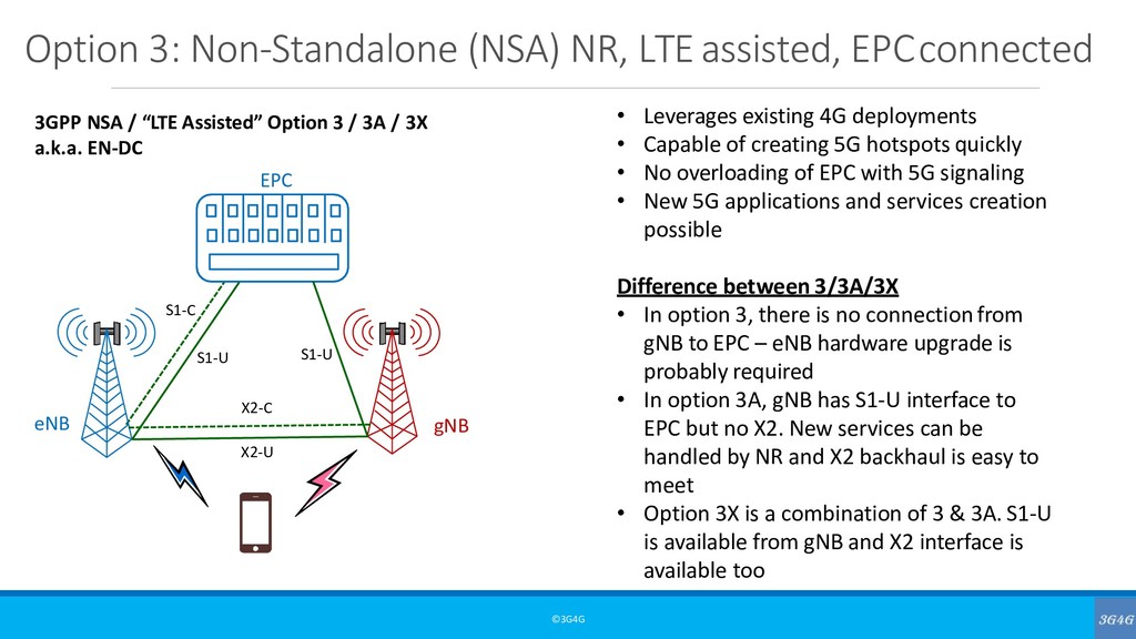
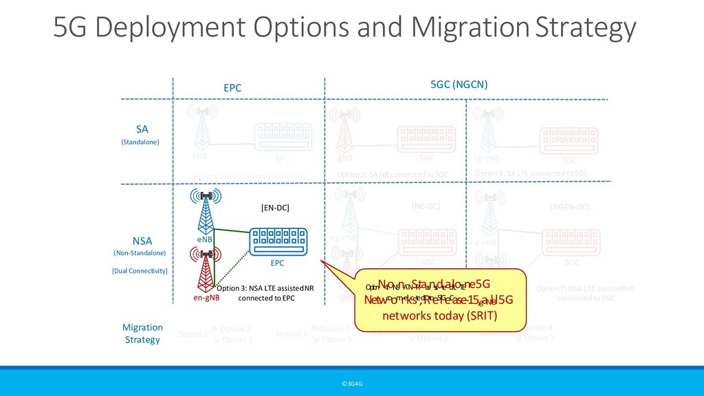
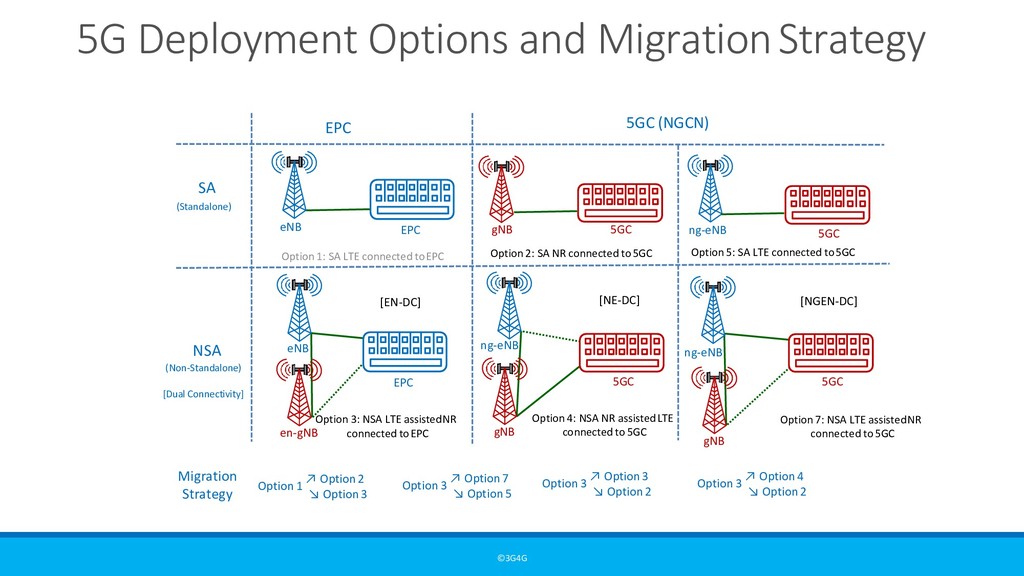
network from 3GPP Rel-8 up to 3GPP Rel-15. For an eNB to connect to a 5G network (Standalone or Non-Standalone), it would have to be 3GPP Release-15 or above. • An eNB only supports legacy E-UTRAN interfaces (S1, X2, etc.) and does not support next-generation interfaces (NG, Xn, etc.). • Next generation nodeB (gNB) – 5G access network from 3GPP Rel-15 onwards. • node providing NR user plane and control plane protocol terminations towards the UE, and connected via the NG interface to the 5GC. • gNB does not support legacy E-UTRAN interfaces
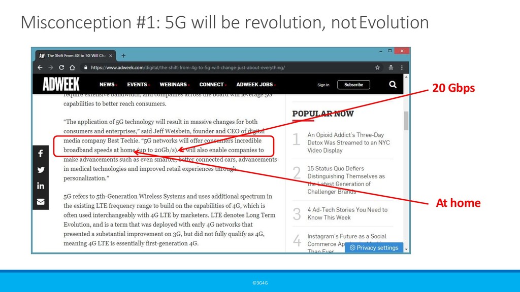
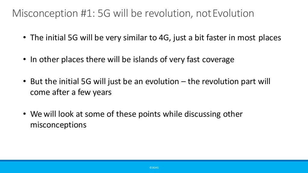
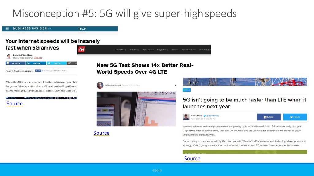
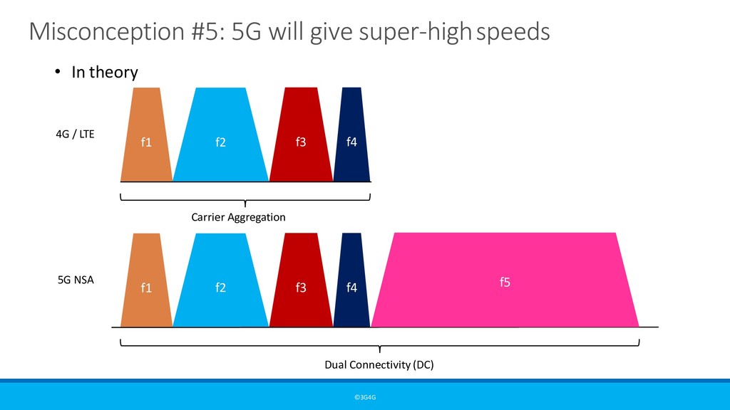
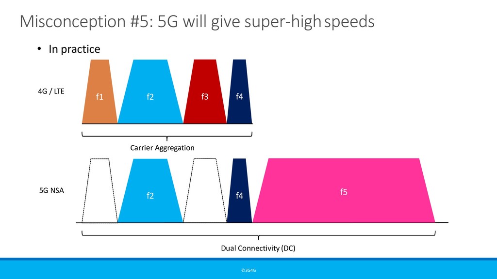
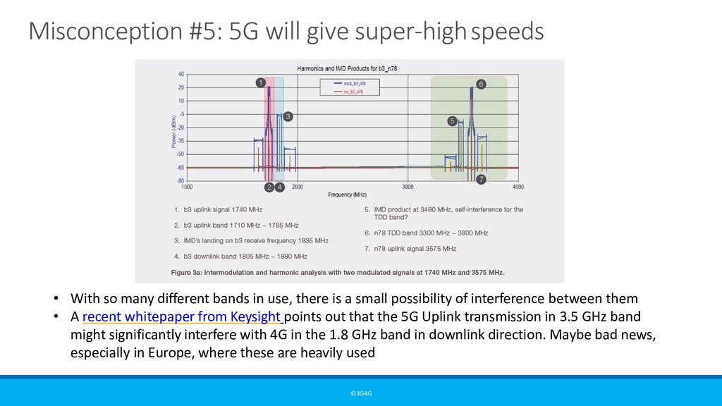
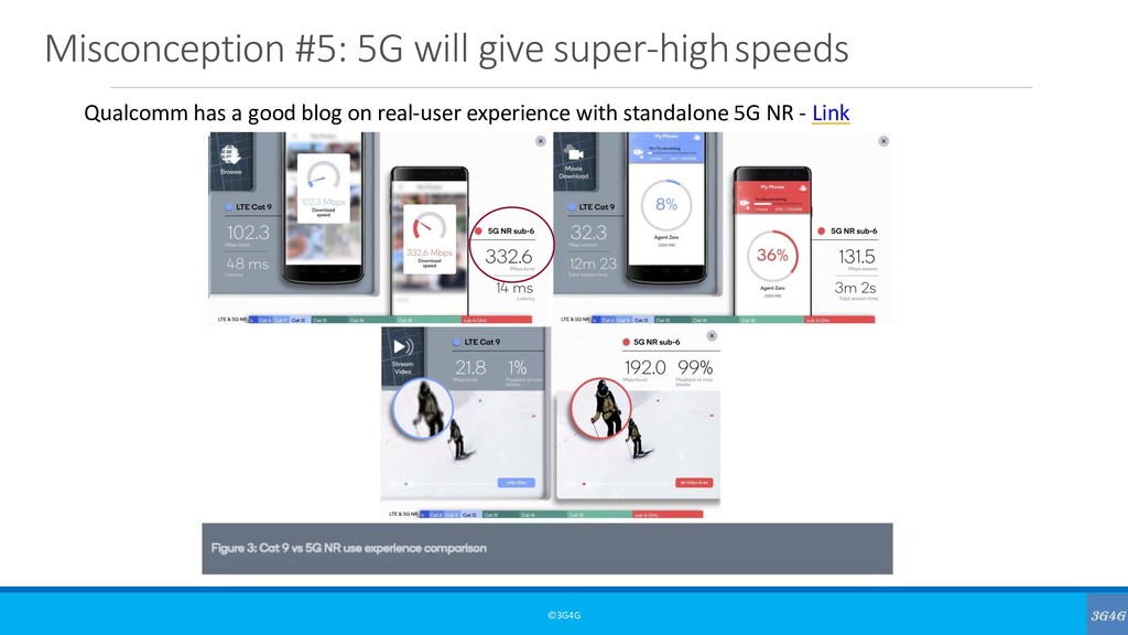
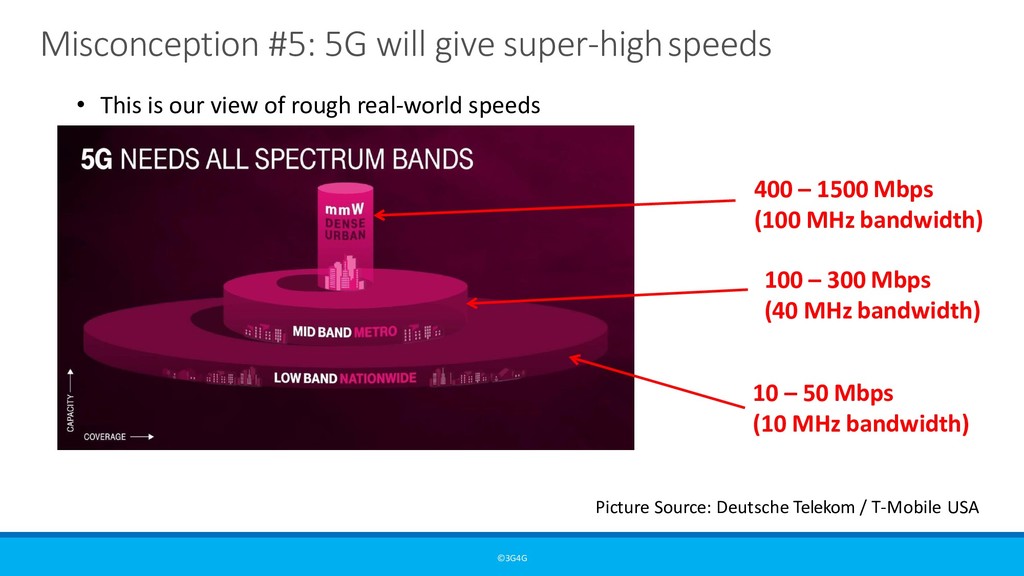
initial 5G will be very similar to 4G, just a bit faster in most places • In other places there will be islands of very fast coverage • But the initial 5G will just be an evolution – the revolution part will come after a few years • We will look at some of these points while discussing other misconceptions
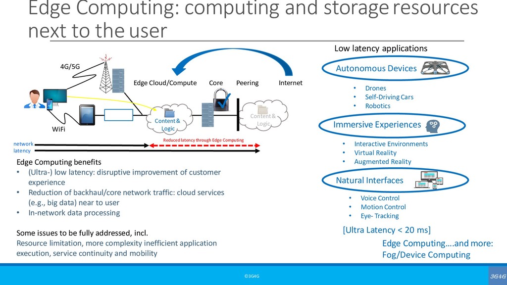
Latency is generally defined as the time it takes for a source to send a packet of data to a receiver. In simple terms, half of Ping time. This is also referred to as one way latency. Sometimes the term Round trip latency or round trip time (RTT) is also used to define latency. This is the same as ping time.
In 3GPP and ITU, control-plane latency and user-plane latency is discussed for a particular technology Control-plane latency is defined as the transition time from idle state to connected state. The user-plane latency, also known as transport delay, is defined as the one- way transit time between a packet being available at the IP layer of the origin and the availability of this packet at IP layer of the destination.
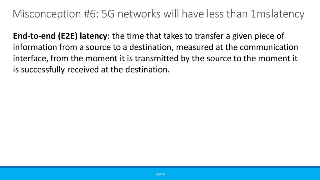
End-to-end (E2E) latency: the time that takes to transfer a given piece of information from a source to a destination, measured at the communication interface, from the moment it is transmitted by the source to the moment it is successfully received at the destination.
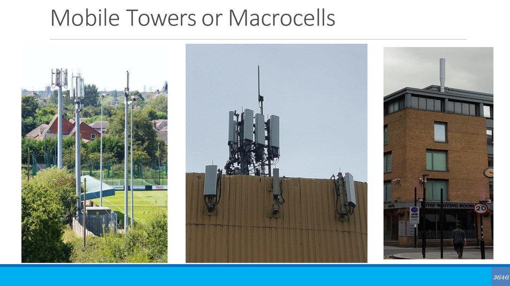
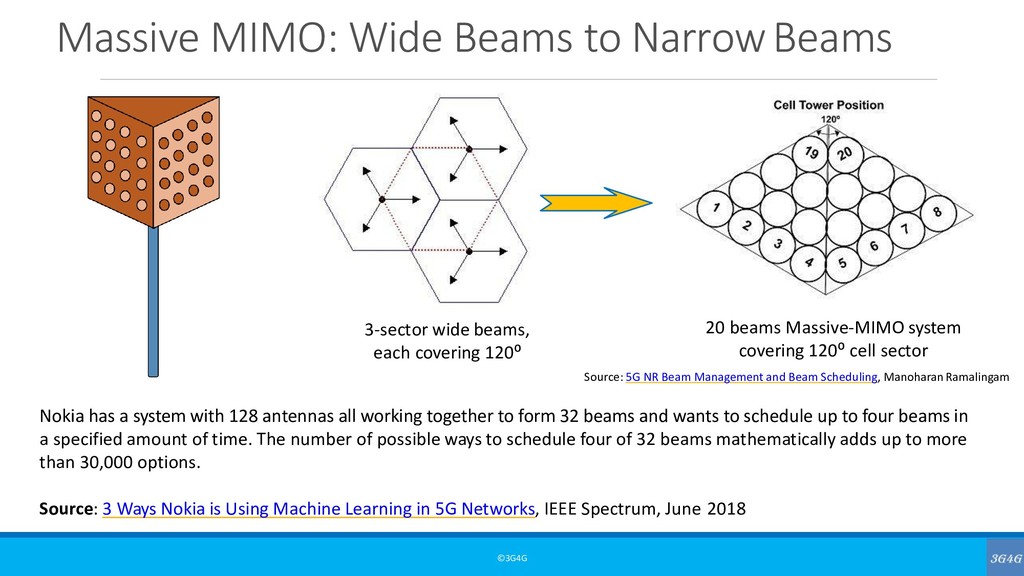
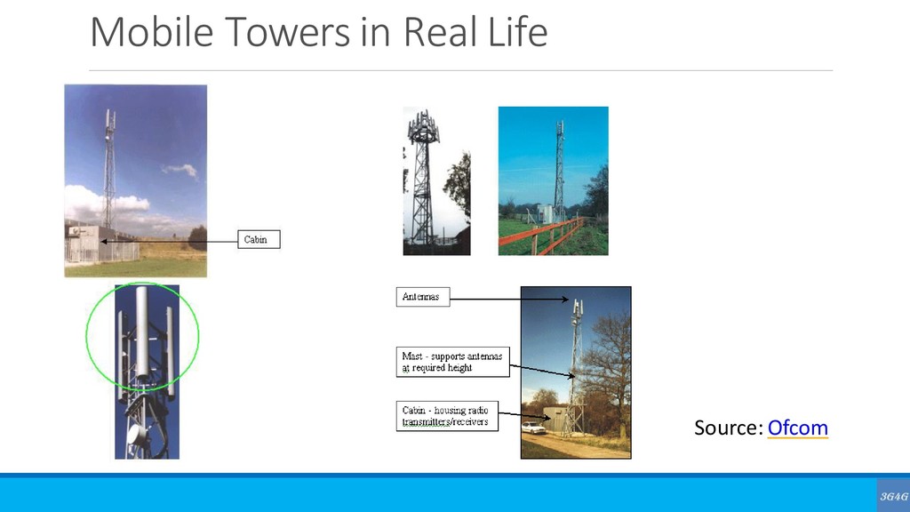
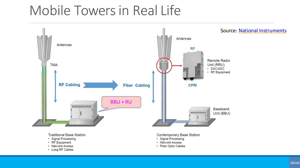
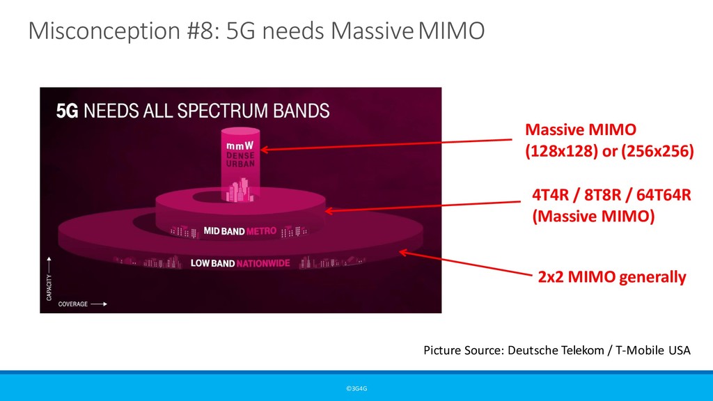
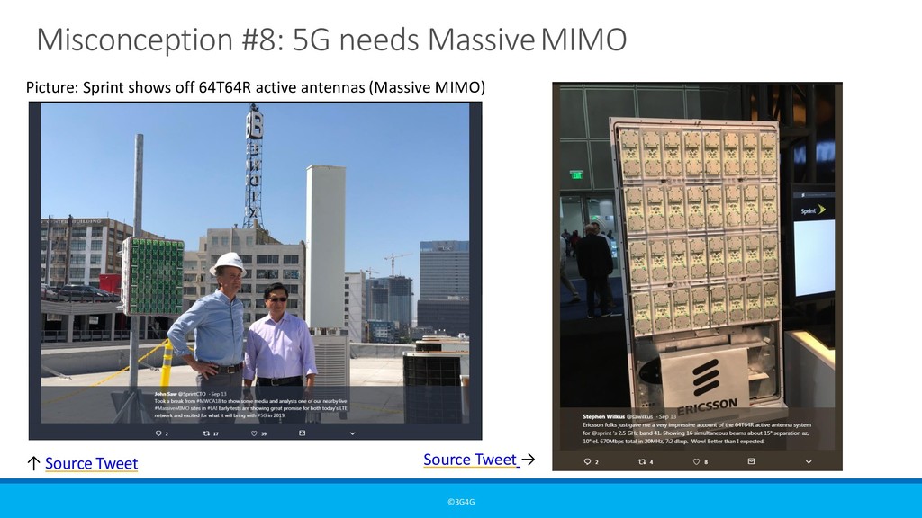
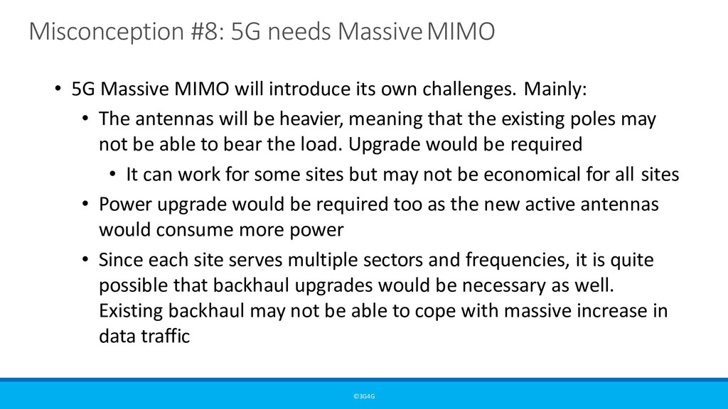
will introduce its own challenges. Mainly: • The antennas will be heavier, meaning that the existing poles may not be able to bear the load. Upgrade would be required • It can work for some sites but may not be economical for all sites • Power upgrade would be required too as the new active antennas would consume more power • Since each site serves multiple sectors and frequencies, it is quite possible that backhaul upgrades would be necessary as well. Existing backhaul may not be able to cope with massive increase in data traffic
generation of mobile technology gives rise to many news and research items suggesting that this new technology is dangerous to health. • For example, back in 2004, Stewart Report looked at all the health concerns and reported that there is no real evidence of health risk. It however also said: “A recent paper has suggested possible effects on brain functioning form the use of 3G or third generation mobile phones. Populations are not homogenous and people can vary in their susceptibility to environmental and other challenges. It was considered that children might be more vulnerable to any effects arising from the use of mobile phones because of their developing nervous system, the greater absorption of energy in the tissues of the head and a longer lifetime exposure.”
been written mentioning that there is no real evidence of any health issues because of mobile phones. • The Observer: Mobile phones and cancer – the full picture • The Argus: New superfast internet won't kill you: expert calms 5G safety fears • Forbes: Is 5G a CIA plot? Finally: • RADIATION HAZARDS - A dabbler’s perspective by Jess H. Brewer
on Non-Ionizing Radiation Protection (ICNIRP): An independent organization provides scientific advice and guidance on the health and environmental effects of non-ionizing radiation (NIR) to protect people and the environment from detrimental NIR exposure. • NIR refers to electromagnetic radiation such as ultraviolet, light, infrared, and radiowaves, and mechanical waves such as infra- and ultrasound. In daily life, common sources of NIR include the sun, household electrical appliances, mobile phones, Wi-Fi, and microwave ovens.
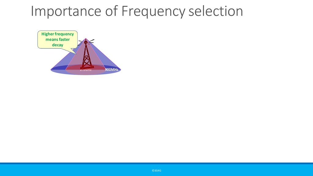
earlier, the coverage layer 5G and capacity layer 5G (sub- 6GHz) have similar properties. With regards to mmWave frequencies, ICNIRP have set safety margins far higher than those for below 6GHz • ICNIRP also provided a Health risk assessment literature with an interesting list of research references. Here is the conclusion regarding Cancer: “Studies of exposure to environmental radiofrequency EMF fields, for example from radio and television transmitters, have not provided evidence of an increased cancer risk either in children or in adults. Studies of cancer in relation to occupational radiofrequency EMF exposure have suffered substantial methodological limitations and do not provide sufficient information for the assessment of carcinogenicity of radiofrequency EMF fields. Taken together, the epidemiological studies do not provide evidence of a carcinogenic effect of radiofrequency EMF exposure at levels encountered in the general population. In summary, no effects of radiofrequency EMF on cancer have been substantiated.”
• There is no research or proof that can conclusively blame any brain issues or cancer on current mobile technologies • The power levels in new mmWave 5G is designed to be much lower than that used for current mobile cellular systems. This means that the risk is even further removed.


 muhannadal
 inesmontani
 katiecoart
 nmsamuel
 jcasabona
 techseoconnect
 trishagee
 stephenakadiri
 thirion
 aleyda
 chriscoyier
 brad_frost
 nonsquared