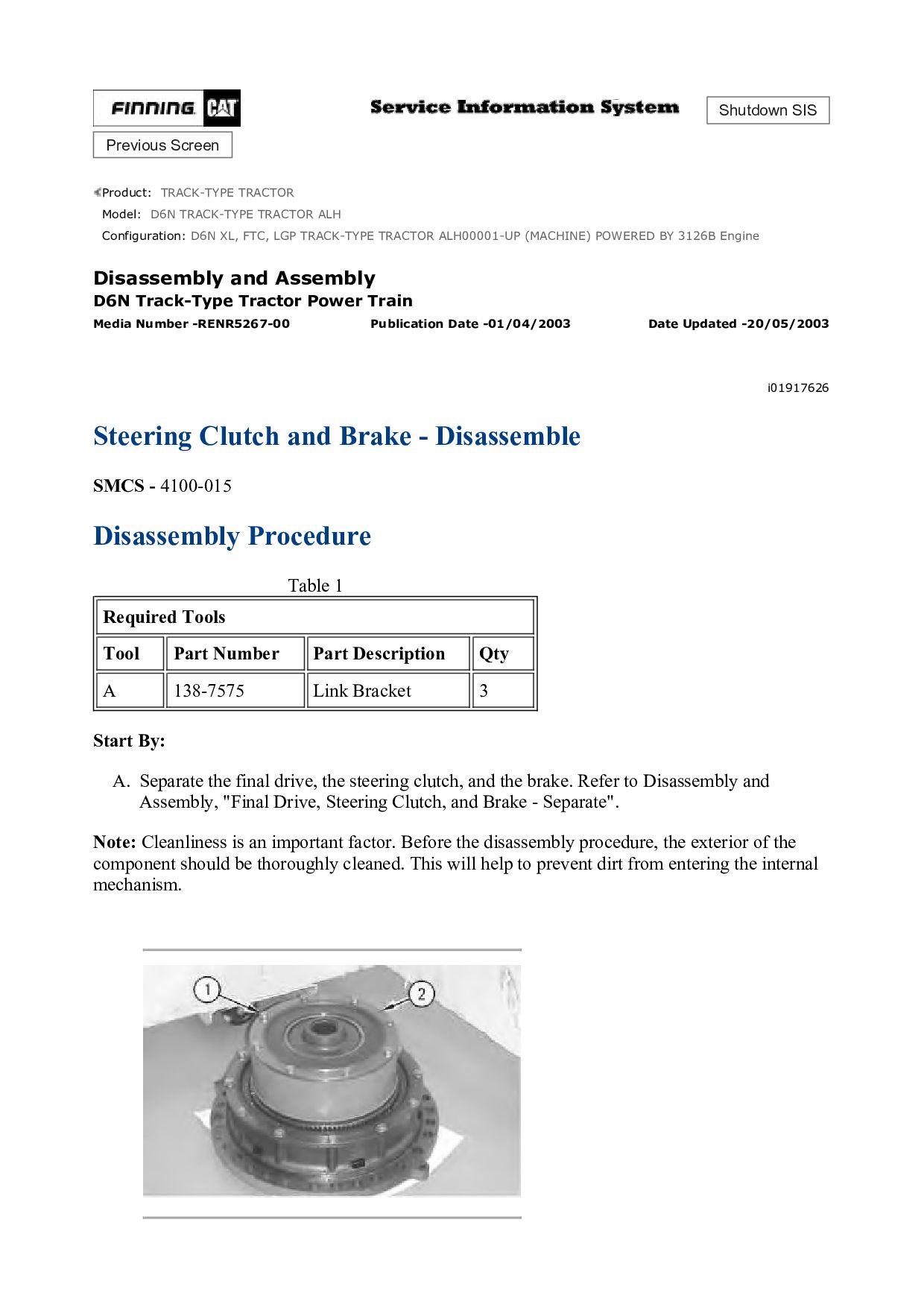
TRACTOR ALH Configuration: D6N XL, FTC, LGP TRACK-TYPE TRACTOR ALH00001-UP (MACHINE) POWERED BY 3126B Engine Disassembly and Assembly D6N Track-Type Tractor Power Train Media Number -RENR5267-00 Publication Date -01/04/2003 Date Updated -20/05/2003 i01917626 Steering Clutch and Brake - Disassemble SMCS - 4100-015 Disassembly Procedure Table 1 Required Tools Tool Part Number Part Description Qty A 138-7575 Link Bracket 3 Start By: A. Separate the final drive, the steering clutch, and the brake. Refer to Disassembly and Assembly, "Final Drive, Steering Clutch, and Brake - Separate". Note: Cleanliness is an important factor. Before the disassembly procedure, the exterior of the component should be thoroughly cleaned. This will help to prevent dirt from entering the internal mechanism.