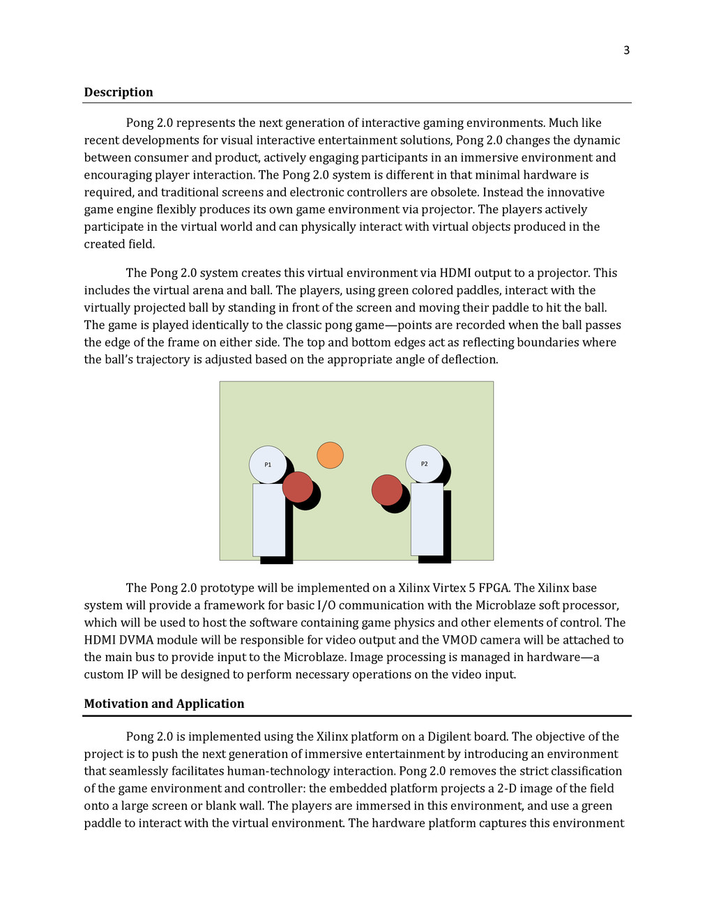
gaming environments. Much like recent developments for visual interactive entertainment solutions, Pong 2.0 changes the dynamic between consumer and product, actively engaging participants in an immersive environment and encouraging player interaction. The Pong 2.0 system is different in that minimal hardware is required, and traditional screens and electronic controllers are obsolete. Instead the innovative game engine flexibly produces its own game environment via projector. The players actively participate in the virtual world and can physically interact with virtual objects produced in the created field. The Pong 2.0 system creates this virtual environment via HDMI output to a projector. This includes the virtual arena and ball. The players, using green colored paddles, interact with the virtually projected ball by standing in front of the screen and moving their paddle to hit the ball. The game is played identically to the classic pong game—points are recorded when the ball passes the edge of the frame on either side. The top and bottom edges act as reflecting boundaries where the ball’s trajectory is adjusted based on the appropriate angle of deflection. P1 P2 The Pong 2.0 prototype will be implemented on a Xilinx Virtex 5 FPGA. The Xilinx base system will provide a framework for basic I/O communication with the Microblaze soft processor, which will be used to host the software containing game physics and other elements of control. The HDMI DVMA module will be responsible for video output and the VMOD camera will be attached to the main bus to provide input to the Microblaze. Image processing is managed in hardware—a custom IP will be designed to perform necessary operations on the video input. Motivation and Application Pong 2.0 is implemented using the Xilinx platform on a Digilent board. The objective of the project is to push the next generation of immersive entertainment by introducing an environment that seamlessly facilitates human-technology interaction. Pong 2.0 removes the strict classification of the game environment and controller: the embedded platform projects a 2-D image of the field onto a large screen or blank wall. The players are immersed in this environment, and use a green paddle to interact with the virtual environment. The hardware platform captures this environment
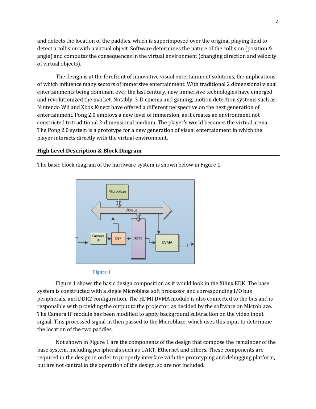
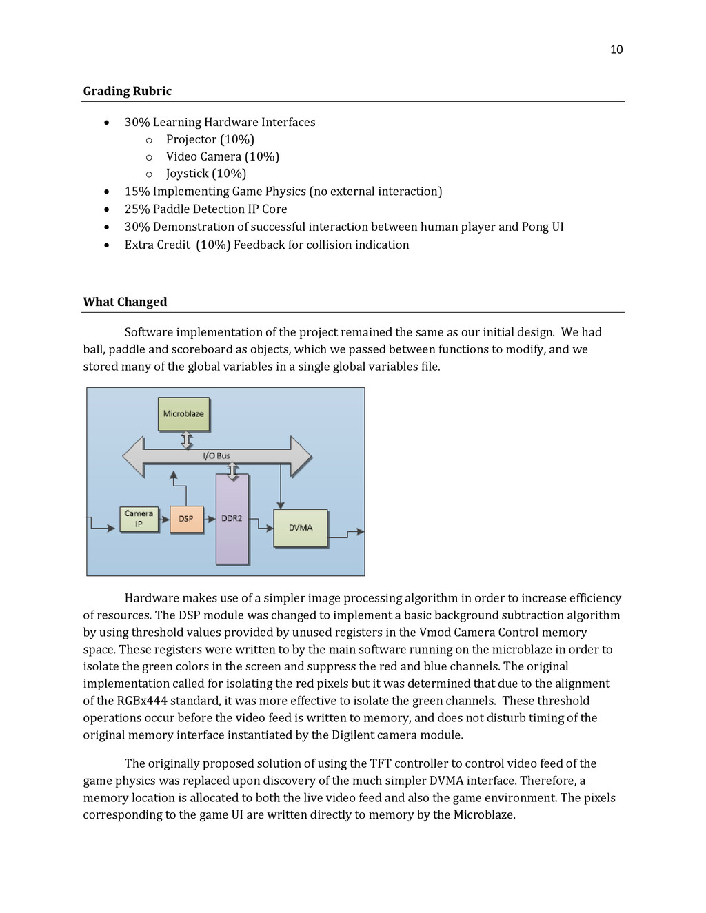
superimposed over the original playing field to detect a collision with a virtual object. Software determines the nature of the collision (position & angle) and computes the consequences in the virtual environment (changing direction and velocity of virtual objects). The design is at the forefront of innovative visual entertainment solutions, the implications of which influence many sectors of immersive entertainment. With traditional 2 dimensional visual entertainments being dominant over the last century, new immersive technologies have emerged and revolutionized the market. Notably, 3-D cinema and gaming, motion detection systems such as Nintendo Wii and Xbox Kinect have offered a different perspective on the next generation of entertainment. Pong 2.0 employs a new level of immersion, as it creates an environment not constricted to traditional 2-dimensional medium. The player’s world becomes the virtual arena. The Pong 2.0 system is a prototype for a new generation of visual entertainment in which the player interacts directly with the virtual environment. High Level Description & Block Diagram The basic block diagram of the hardware system is shown below in Figure 1. Figure 1 Figure 1 shows the basic design composition as it would look in the Xilinx EDK. The base system is constructed with a single Microblaze soft processor and corresponding I/O bus peripherals, and DDR2 configuration. The HDMI DVMA module is also connected to the bus and is responsible with providing the output to the projector, as decided by the software on Microblaze. The Camera IP module has been modified to apply background subtraction on the video input signal. This processed signal in then passed to the Microblaze, which uses this input to determine the location of the two paddles. Not shown in Figure 1 are the components of the design that compose the remainder of the base system, including peripherals such as UART, Ethernet and others. These components are required in the design in order to properly interface with the prototyping and debugging platform, but are not central to the operation of the design, so are not included.
in the block diagram, is actually a modified output stage of the Camera IP core. This portion of the core is required since the nature of the design requires that the system is highly responsive to motion—the positions of the paddles must be known in real time so performance of the DSP is critical. The DSP forwards the processed video feed over the PLB to the Microblaze, which determines the corresponding paddle positions. It then compares these positions with the position of the virtual ball, and determines if a collision is detected. If there is a collision between a paddle and a ball, the software will calculate the angle of the collision to determine the new trajectory of the ball, which is applied in the following frames. In-game physics is also handled by the software. If an upper or lower edge is detected, then the software calculates the angle at which the collision occurs, and deflects the ball on its new trajectory. A point system is also recorded, with a point recorded for every collision with a side edge. Hardware background subtraction is used in the paddle detection portion of the modified Camera IP core. This is achieved by masking and filtering the pixel values read from the camera. This forms a basic filter that only lets those pixels of the desired paddle color pass. The mean location of these pixels can then be determined, functioning as the position of the center of the virtual paddle. System Components FPGA This will function as the central controller for our game system. It will handle input and output signals, interfacing with all other component. It will also have the responsibility of analyzing the video input, simulating the physics of our game, and generating the video output. Stereo Camera One camera will be used to receive input from those playing the game. It will output a raw video signal to the FPGA, which will process this signal and pass it to the Microblaze CPU, which will translate it to input to the physical model of the game. Joystick The onboard FPGA joystick will be used as an alternate input to our game. This input will then be used to control a virtual paddle within the game. The paddle moves at a predefined speed in the direction corresponding to the direction the joystick is pressed. Projector The projector will be used to display the current state of the game and is the primary output of the system. The FPGA will interface with this component through an HDMI signal output using an HDMI IP Core. Serial Output This was used for debugging throughout the development process of our application.
as input devices for the game and will be recognized by the image processing IP core on the FPGA. In future development, these paddles may include feedback to the user, either in the form of illumination, sound, or vibration. AC97 Audio Module This is implemented as extra credit for our project. In-game sound effects are generated by this module when various events occur including collisions with walls and paddles, point score events, and game over events. These sound effects are localized to the side of the playing field on which they occur. I/O Description As mentioned in the previous high-level description of Pong 2.0 our project consists of five different components: the MicroBlaze soft-MCU, HDMI module, camera module, DSP module, and the onboard joystick input module. The two modules directly handling input are the joystick and the stereo video camera. The joystick module receives input in the form of button presses in one of four directions. Button presses are read from this module simply by checking the values in the associated register. The video input is delivered to the main FPGA board through a parallel bus in s processed RGB format. Control of this input module is achieved over an I2C interface. Several onboard switches are used to configure characteristics of the game and debugging output. The output for our system consists primarily of an HDMI signal that is fed into a projector. This signal consists of a rectangular playing field as well a virtual ball that obeys physics given by our game engine. There is also a small portion of the screen reserved for displaying the score of each of the two players. Sound output is also present in the form of basic effects that are triggered during certain game events. Some alternate outputs that could be included in future implementations are vibration or optical feedback in the paddles themselves, triggered when a collision with the ball occurs. We also use the serial output for debugging purposes during the development process. Implementation Details Specific implementation details are close to the originally proposed system. The hardware platform depicted in Fig.1 is an updated view of the base system constructed in XPS. The image detection is no longer its own IP, but integrated within the VMOD control IP module. This simplifies design and does not require building an IP from scratch. The image detection thresholds make use of unused but allocated registers in the VMOD camera IP so that the sensitivity of the background subtraction can be tuned. The processed data is sent to the VFBC interface where it is read by the Microblaze to determine paddle positions. Detection of a Paddle center position relies on the fast yet simple algorithm that scans the screens and detects the median of the location of green paddles in the x direction. In the y direction, the same scan is performed but only for every 8 lines to increase the speed of the algorithm without losing much accuracy. Assignment of the center is sent to the game engine.
of the screen (1280x720) and maintains this color data in memory. It also tracks positions of paddles and the ball. If an edge is detected by the square bounding box around the ball, then the appropriate action is determined (score, paddle detected, upper and lower wall collision, etc). The game also records points for a ball that leaves the view of the screen. The game ends when a fixed number of points is reached (may be 5 to 10 but is hard coded). The main code maintains 2 predetermined memory locations (one dedicated to video data from the VMOD camera and the other for the game environment). Therefore the DVMA need only to point to the right location to provide the correct video feed. Testing Unit tests will be required for each module created by our team. The DVMA and MicroBlaze modules can be assumed reliable. If problems occur that cannot be attributed to other modules, these modules will be inspected as a final measure. Along with testing of these individual modules, the code running on the MicroBlaze processor must also be tested . This includes the physics engine and code translating the state of the ball to the visual representation of the playing field, as well as the code responsible for processing inputs from the DSP and joystick. The camera module can be testing by capturing images and storing them into the FPGA memory. These images can then be directly output to a monitor to observe if the image capture process was successful. This basic testing should be enough to ensure that the physical camera module is functioning. We observed the output to the screen. We also have a switch on the FGPA board that toggles between the video feed and the game projection. Testing of the code to render the playing field is also necessary. This can be achieved simply by creating functions for rendering rectangles and circles in at various coordinates on the screen and observing the video output on the monitor and projector. We observed the objects moving by checking their actual values in memory. Testing the scoreboard was necessary to make sure that the values only go up to the value set as the winning score. This revealed flaws in our logic which were fixed. After this basic rendering is achieved, the physics engine will be implemented and the ball’s physics can be tested. First, a fully-enclosed playing field will be simulated, where the ball will bounce off of any portion of the playing field border. We will then move on to test the more sophisticated physics of the game, bouncing the ball off of different areas of a fixed paddle with differing incoming trajectories. We took care to check boundary conditions to make sure that moving the ball or paddle to the bounds of our game would not break the game. In order to further test gameplay without dependence on signal processing, the joystick input will be used. This requires a basic test of joystick functionality, outputting values for the position of the joystick relative to its center, resting position. After the joystick module is determined to be reliable, the gameplay physics can be tested in conjunction with the projector output, using joysticks to control virtual paddles. We encountered bugs with value bounding here
was done via DIP switch and register programming. Since the threshold levels for the background subtraction and color rejection were software programmable, various levels for the upper and lower threshold of the green and white pixel intensities could be tuned on the fly without rebuilding the base system. In addition, DIP switches were used to control various threshold configurations so multiple thresholds could be applied to the same system without having to rebuild the FPGA elf file. The center position of the paddle was detected and via median computation and the values were printed via UART to a serial terminal. The final test will incorporate all of these aforementioned modules, using the video as input to control a full game session of Pong 2.0. Here we will find what bugs result in the combination of all of these independent modules and polish our final product. Overall, the game seems fairly resistant to bugs as we have a limited finite state machine. Realistic Constraints There are various constraints we impose on our system. These constraints are both imposed by our team and those created by our limited resources. The economic constraints give that the system is a video game, but that our consumers do not likely have access to an FPGA and the specialized software needed to compile and run our software on their systems. While it is possible to change our software to a precompiled version, the FGPA board we use has a variety of functionalities on it that we will never use for this project. Thus, we are constrained economically by the FPGA board and software. However, we want our other attachments to be very cheap. Our projector is a common projector found in most classrooms and our CMOS analog video camera is not tremendously expensive in contrast to our FPGA board and software. The environmental restraints in our system comprise of the physical environment our game needs to successfully work. We constrain our projector and camera to face a flat wall or surface. While it might be possible to account for skews in our DSP IP core, it seems excessively difficult. This constraint will make our overall design much simpler in the DSP IP core. In addition, we constrain the area to be well lit and not overly dusty. Both could reduce the effectiveness of our DSP algorithms. The social restraints in our system are few. This is a video game at its core so we have few constraints other than only allowing two players at a time. While it is possible to change the game to add additional players, the essence of pong is still a 2-player game. Thus we wanted to keep the essence of the classical game. As a workaround, additional players can simply trade positions with the current players. In addition, another possible expansion for the future is to record the video and score and allow players to share their scores online. However, we have no current plans to address this.
Our system is subject to all the same laws that normal video games are subject to. We can assume that the age rating on our game will be the same as the original pong, which is 3+. The ethical restraints on our system include disability access. We have attempted to address this by adding a joystick, which can be used by those who lack lower motor control to play our game. However, we don’t address other potential disabilities such as blindness or lack of arm control. Our ethical constraint here is a best-effort constraint to address disabilities. It’s very difficult for games to address all possible forms of disabilities so we have chosen to address one common disability. The health and safety constraints on our system are centered on the video projection and spatial safety issues. Video projection can cause epileptic seizures. We constrain this game to those who do not have this condition and have reasonable eyesight. In addition, since our players will have to move the paddles around, the system will be unsafe if the players have not cleared out the video projection area. Potential tripping hazards or other impact hazards are safety concerns. The manufacturability constraints on our system result from our hardware. The software processing is not trivial so we require a processor with sufficient speed to process the video input and output. If we were to manufacture this as an actual game, we likely would not use the entire FGPA board but a PCB with the needed components. Then, we need a plastic wrapping around the PCB to insulate the users from damaging the board automatically and a way to load our software on the board. We will also likely have to do much more extensive testing for a commercial product. Labor Division Raymond worked primarily on the software end. Specifically, he worked on the physics engine and the software framework and classes. He also implemented the ball and paddle screen displays, suggested using the median as a outlier-resistant paddle detection method, and implemented overall game functionality in creating new games. Julian focused first on UI environment design and coding, and also worked on bringing up the hardware platforms. He later lead the effort of implementing and tuning the background subtraction mechanism for detecting the paddles and strengthening robustness of the hardware/software platform. Julian also focused on paddle detection in software, by realizing the median detection and center position assignment. Brandon focused on the hardware and integration of the project, initially focusing on enabling the camera IP and video memory interface. He also worked with the background subtraction algorithm with Julian to reliably reject unwanted objects from the camera's view. He later worked on integrating the hardware and software platforms that were being developed independently and enabled hardware features such as AC97, UART and GPIO switches.
(10%) o Video Camera (10%) o Joystick (10%) 15% Implementing Game Physics (no external interaction) 25% Paddle Detection IP Core 30% Demonstration of successful interaction between human player and Pong UI Extra Credit (10%) Feedback for collision indication What Changed Software implementation of the project remained the same as our initial design. We had ball, paddle and scoreboard as objects, which we passed between functions to modify, and we stored many of the global variables in a single global variables file. Hardware makes use of a simpler image processing algorithm in order to increase efficiency of resources. The DSP module was changed to implement a basic background subtraction algorithm by using threshold values provided by unused registers in the Vmod Camera Control memory space. These registers were written to by the main software running on the microblaze in order to isolate the green colors in the screen and suppress the red and blue channels. The original implementation called for isolating the red pixels but it was determined that due to the alignment of the RGBx444 standard, it was more effective to isolate the green channels. These threshold operations occur before the video feed is written to memory, and does not disturb timing of the original memory interface instantiated by the Digilent camera module. The originally proposed solution of using the TFT controller to control video feed of the game physics was replaced upon discovery of the much simpler DVMA interface. Therefore, a memory location is allocated to both the live video feed and also the game environment. The pixels corresponding to the game UI are written directly to memory by the Microblaze.
successful, paddle detection is inconsistent and unreliable. The paddle must be held at a small tilt to the system for the system to detect the paddle. We could get much better reliability by doing better calibration and implementing a motion detection algorithm rather than a simple green threshold algorithm. We used medians to avoid outliers in the paddle detection. This worked very well as we verified via serial. We had our main game in a tight for loop, which meant we were limited by how fast the processor was. In retrospect, it would have been more optimal to have a blocking scheme or some other scheme to have fine-tuned control over the clock and to waste less system resources. Most importantly, the game is fun to play and it works. There is a lack of major bugs and it is easily modifiable to add features due to our modular design.


 takonda
 pfn
 codatum
 jozono
 kzkhykw1991
 grimoh
 mhrtech
 occhi
 endonanana
 riyaamemiya
 satomasahiro2005
 sh_fk2
 techseoconnect
 jonyablonski
 427marketing
 cargoodrich
 sstephenson
 jonoalderson
 jacobian
 axbom
 frankvandijk
 mraible
 ryanjones
 nikkihalliwell