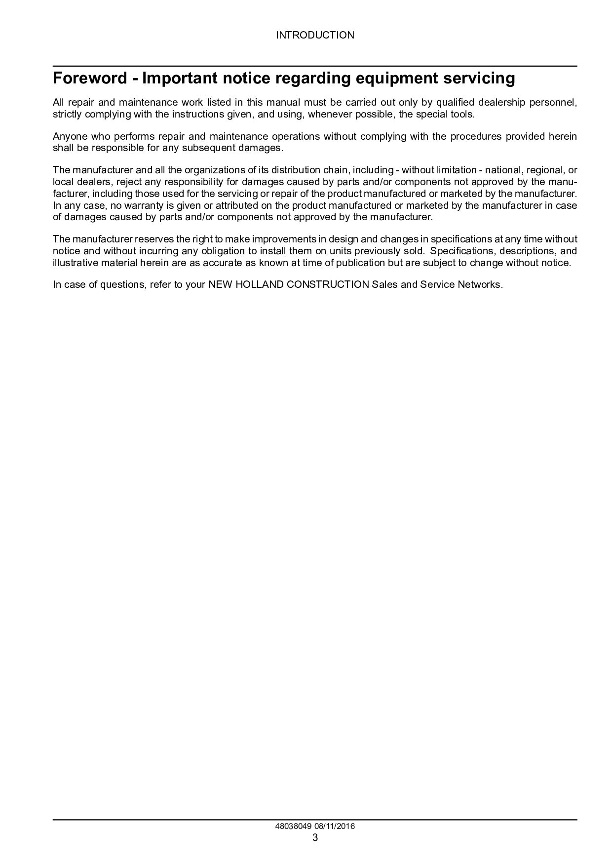
and maintenance work listed in this manual must be carried out only by qualified dealership personnel, strictly complying with the instructions given, and using, whenever possible, the special tools. Anyone who performs repair and maintenance operations without complying with the procedures provided herein shall be responsible for any subsequent damages. The manufacturer and all the organizations of its distribution chain, including - without limitation - national, regional, or local dealers, reject any responsibility for damages caused by parts and/or components not approved by the manu- facturer, including those used for the servicing or repair of the product manufactured or marketed by the manufacturer. In any case, no warranty is given or attributed on the product manufactured or marketed by the manufacturer in case of damages caused by parts and/or components not approved by the manufacturer. The manufacturer reserves the right to make improvements in design and changes in specifications at any time without notice and without incurring any obligation to install them on units previously sold. Specifications, descriptions, and illustrative material herein are as accurate as known at time of publication but are subject to change without notice. In case of questions, refer to your NEW HOLLAND CONSTRUCTION Sales and Service Networks. 48038049 08/11/2016 3
4B (Final) NA B95C TC Four-Wheel Drive (4WD) Tier 4B (Final) NA B95C Two-Wheel Drive (2WD) Tier 4B (Final) NA Personal safety This is the safety alert symbol. It is used to alert you to potential personal injury hazards. Obey all safety messages that follow this symbol to avoid possible death or injury. Throughout this manual you will find the signal words DANGER, WARNING, and CAUTION followed by special in- structions. These precautions are intended for the personal safety of you and those working with you. Read and understand all the safety messages in this manual before you operate or service the machine. DANGER indicates a hazardous situation that, if not avoided, will result in death or serious injury. WARNING indicates a hazardous situation that, if not avoided, could result in death or serious injury. CAUTION indicates a hazardous situation that, if not avoided, could result in minor or moderate injury. FAILURE TO FOLLOW DANGER, WARNING, AND CAUTION MESSAGES COULD RESULT IN DEATH OR SERIOUS INJURY. Machine safety NOTICE: Notice indicates a situation that, if not avoided, could result in machine or property damage. Throughout this manual you will find the signal word Notice followed by special instructions to prevent machine or property damage. The word Notice is used to address practices not related to personal safety. Information NOTE: Note indicates additional information that clarifies steps, procedures, or other information in this manual. Throughout this manual you will find the word Note followed by additional information about a step, procedure, or other information in the manual. The word Note is not intended to address personal safety or property damage. 48038049 08/11/2016 4
operate the machine on slopes. Raised equipment, full tanks and other loads will change the center of gravity of the machine. The machine can tip or roll over when near ditches and embankments or uneven surfaces. Never permit anyone other than the operator to ride on the machine. Never operate the machine under the influence of alcohol or drugs, or while you are otherwise impaired. When digging or using ground-engaging attachments, be aware of buried cables. Contact local utilities to determine the locations of services. Pay attention to overhead power lines and hanging obstacles. High voltage lines may require significant clearance for safety. Hydraulic oil or diesel fuel leaking under pressure can penetrate the skin, causing serious injury or infection. • DO NOT use your hand to check for leaks. Use a piece of cardboard or paper. • Stop the engine, remove the key, and relieve the pressure before you connect or disconnect fluid lines. • Make sure that all components are in good condition. Tighten all connections before you start the engine or pres- surize the system. • If hydraulic fluid or diesel fuel penetrates the skin, seek medical attention immediately. • Continuous long term contact with hydraulic fluid may cause skin cancer. Avoid long term contact and wash the skin promptly with soap and water. Keep clear of moving parts. Loose clothing, jewelry, watches, long hair, and other loose or hanging items can become entangled in moving parts. Wear protective equipment when appropriate. DO NOT attempt to remove material from any part of the machine while it is being operated or while components are in motion. Make sure that all guards and shields are in good condition and properly installed before you operate the machine. Never operate the machine with shields removed. Always close access doors or panels before you operate the ma- chine. Dirty or slippery steps, ladders, walkways, and platforms can cause falls. Make sure these surfaces remain clean and clear of debris. A person or pet within the operating area of a machine can be struck or crushed by the machine or its equipment. DO NOT allow anyone to enter the work area. Raised equipment and/or loads can fall unexpectedly and crush persons underneath. Never allow anyone to enter the area underneath raised equipment during operation. Never operate the engine in enclosed spaces as harmful exhaust gases may build up. Before you start the machine, be sure that all controls are in neutral or park lock position with the backhoe swing lock pin in the lock position. The backhoe swing lock pin must be in the lock position when you are not using the backhoe. Start the engine only from the operator’s seat. If you bypass the safety start switch, the engine can start with the transmission in gear. Do not connect or short across terminals on the starter solenoid. Attach jumper cables as described in the manual. Starting in gear may cause death or serious injury. Always keep windows, mirrors, all lighting, and Slow-Moving Vehicle (SMV) emblem clean to provide the best possible visibility while you operate the machine. 48038049 08/11/2016 5
except for those controls expressly intended for use from other locations. From the operator's platform, install the backhoe swing lock pin when the backhoe is not in use and before all other operation. Before you leave the machine: 1. Park the machine on a firm, level surface. 2. Put all controls in neutral or park lock position. 3. Engage the parking brake. Use wheel chocks if required. 4. Lower the loader bucket or other front attachment to the ground. 5. Move the operator’s seat to the backhoe operating position and choose one of the following backhoe positions: • Move the backhoe into the stowed position and from the operator's seat install the backhoe swing lock pin. See Cab - Localization overview (90.150). • Lower the backhoe bucket or other attachment to the ground. 6. Turn off the engine and remove the key. 7. Move the operator’s seat into the driving position. When, due to exceptional circumstances, you decide to keep the engine running after you leave the operator’s station, then you must follow these precautions: 1. Bring the engine to low idle speed. 2. Disengage all drive systems. WARNING Some components may continue to run down after you disengage drive systems. Make sure all drive systems are fully disengaged. Failure to comply could result in death or serious injury. W0113A 48038049 08/11/2016 6
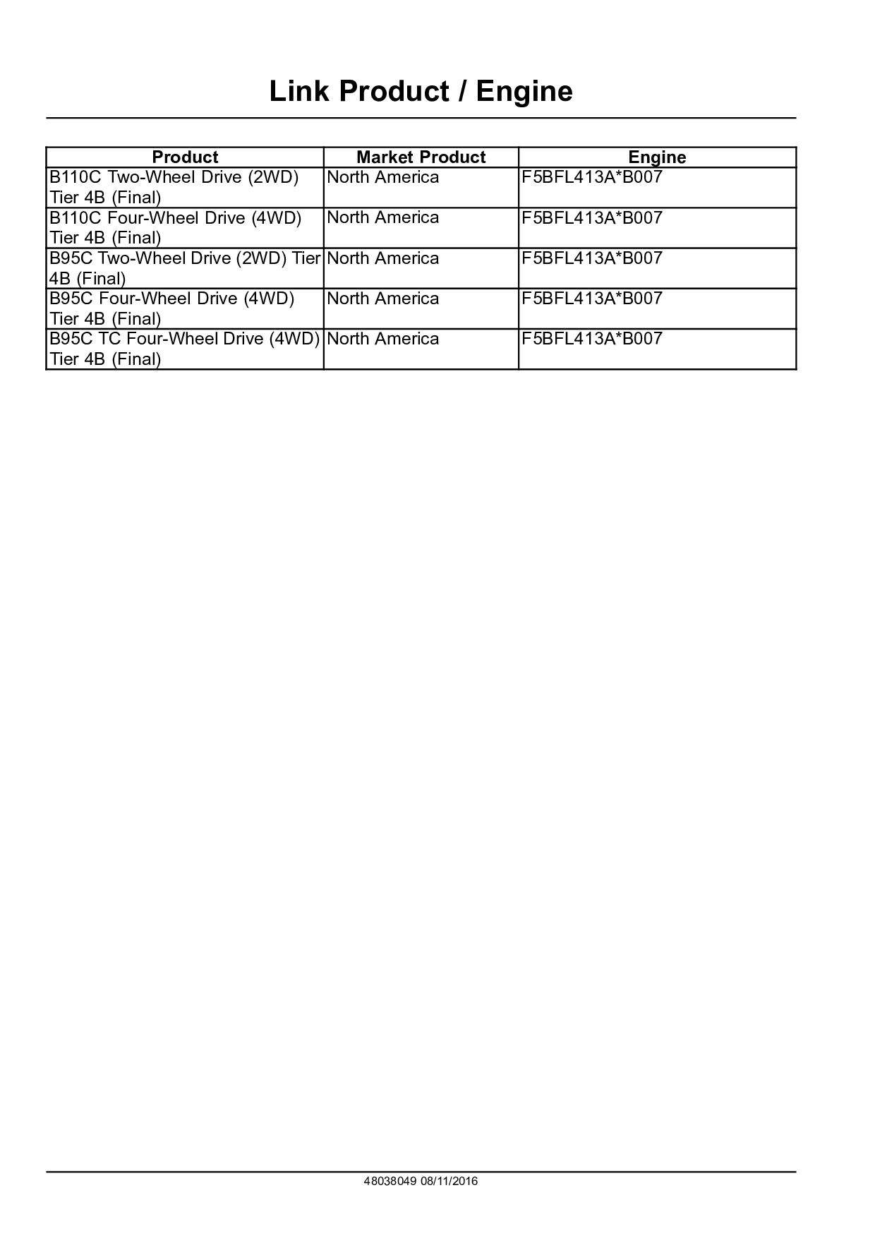
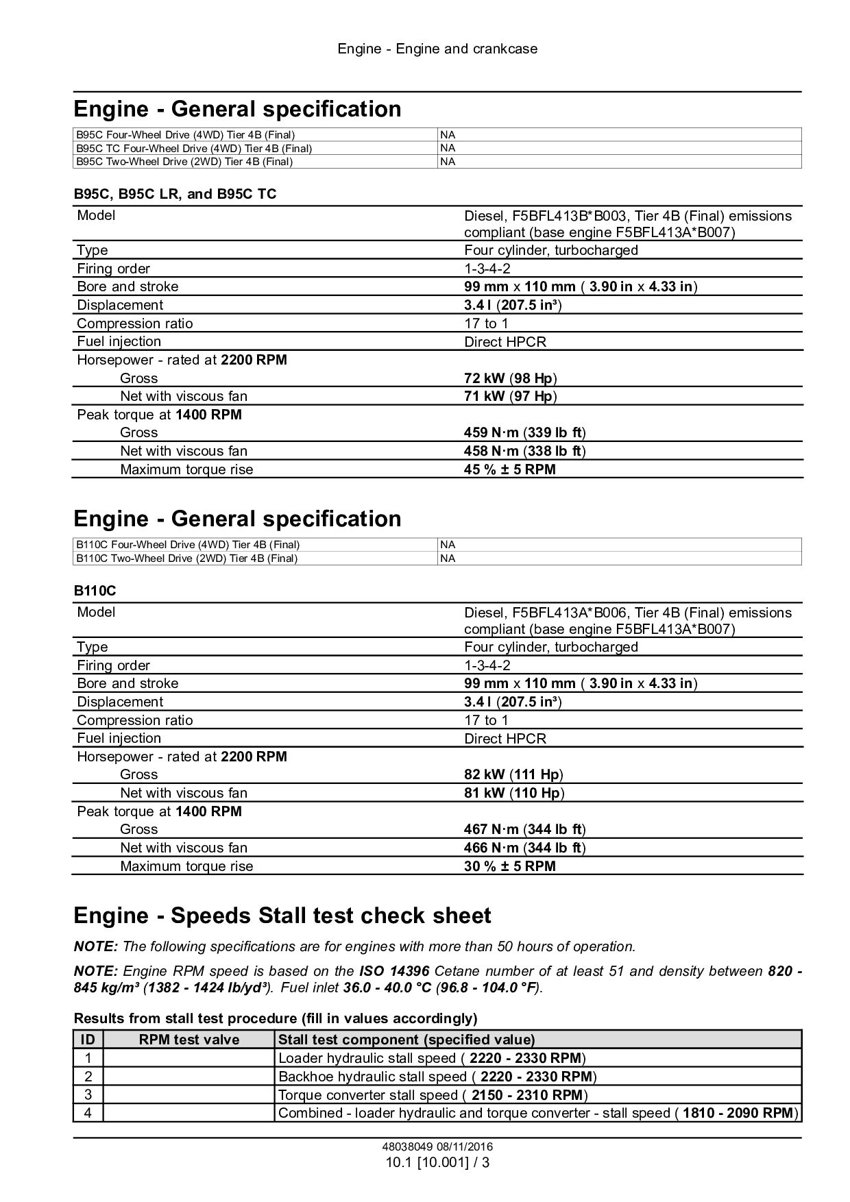
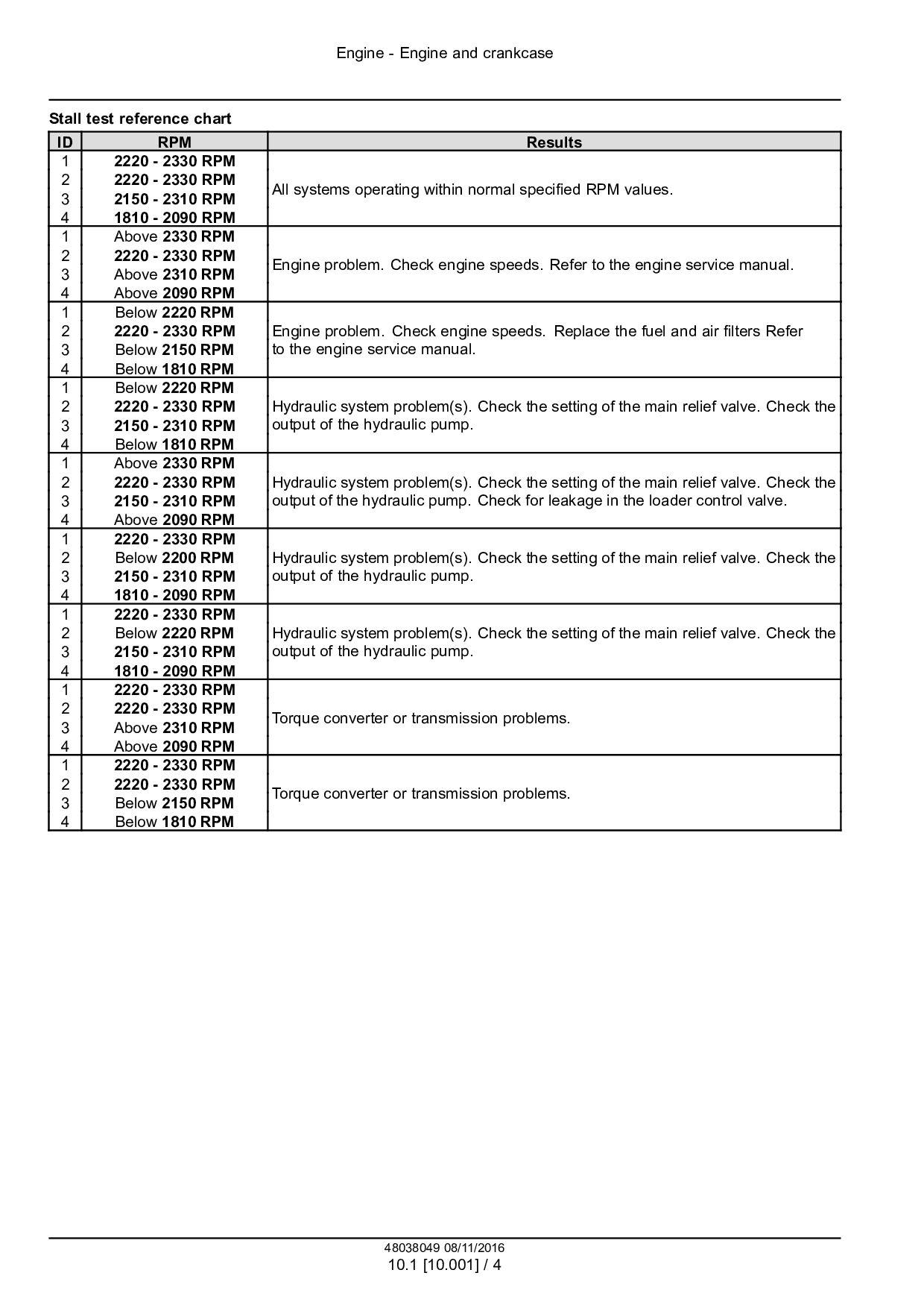
Four-Wheel Drive (4WD) Tier 4B (Final) NA B95C TC Four-Wheel Drive (4WD) Tier 4B (Final) NA B95C Two-Wheel Drive (2WD) Tier 4B (Final) NA B95C, B95C LR, and B95C TC Model Diesel, F5BFL413B*B003, Tier 4B (Final) emissions compliant (base engine F5BFL413A*B007) Type Four cylinder, turbocharged Firing order 1-3-4-2 Bore and stroke 99 mm x 110 mm ( 3.90 in x 4.33 in) Displacement 3.4 l (207.5 in³) Compression ratio 17 to 1 Fuel injection Direct HPCR Horsepower - rated at 2200 RPM Gross 72 kW (98 Hp) Net with viscous fan 71 kW (97 Hp) Peak torque at 1400 RPM Gross 459 N·m (339 lb ft) Net with viscous fan 458 N·m (338 lb ft) Maximum torque rise 45 % ± 5 RPM Engine - General specification B110C Four-Wheel Drive (4WD) Tier 4B (Final) NA B110C Two-Wheel Drive (2WD) Tier 4B (Final) NA B110C Model Diesel, F5BFL413A*B006, Tier 4B (Final) emissions compliant (base engine F5BFL413A*B007) Type Four cylinder, turbocharged Firing order 1-3-4-2 Bore and stroke 99 mm x 110 mm ( 3.90 in x 4.33 in) Displacement 3.4 l (207.5 in³) Compression ratio 17 to 1 Fuel injection Direct HPCR Horsepower - rated at 2200 RPM Gross 82 kW (111 Hp) Net with viscous fan 81 kW (110 Hp) Peak torque at 1400 RPM Gross 467 N·m (344 lb ft) Net with viscous fan 466 N·m (344 lb ft) Maximum torque rise 30 % ± 5 RPM Engine - Speeds Stall test check sheet NOTE: The following specifications are for engines with more than 50 hours of operation. NOTE: Engine RPM speed is based on the ISO 14396 Cetane number of at least 51 and density between 820 - 845 kg/m³ (1382 - 1424 lb/yd³). Fuel inlet 36.0 - 40.0 °C (96.8 - 104.0 °F). Results from stall test procedure (fill in values accordingly) ID RPM test valve Stall test component (specified value) 1 Loader hydraulic stall speed ( 2220 - 2330 RPM) 2 Backhoe hydraulic stall speed ( 2220 - 2330 RPM) 3 Torque converter stall speed ( 2150 - 2310 RPM) 4 Combined - loader hydraulic and torque converter - stall speed ( 1810 - 2090 RPM) 48038049 08/11/2016 10.1 [10.001] / 3
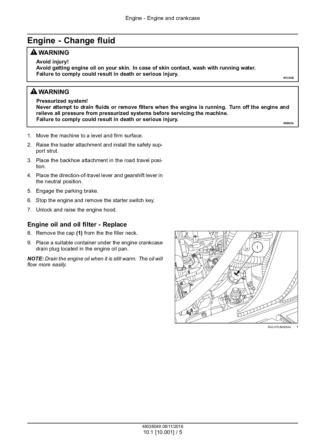
Avoid injury! Avoid getting engine oil on your skin. In case of skin contact, wash with running water. Failure to comply could result in death or serious injury. W1336B WARNING Pressurized system! Never attempt to drain fluids or remove filters when the engine is running. Turn off the engine and relieve all pressure from pressurized systems before servicing the machine. Failure to comply could result in death or serious injury. W0905A 1. Move the machine to a level and firm surface. 2. Raise the loader attachment and install the safety sup- port strut. 3. Place the backhoe attachment in the road travel posi- tion. 4. Place the direction-of-travel lever and gearshift lever in the neutral position. 5. Engage the parking brake. 6. Stop the engine and remove the starter switch key. 7. Unlock and raise the engine hood. Engine oil and oil filter - Replace 8. Remove the cap (1) from the the filler neck. 9. Place a suitable container under the engine crankcase drain plug located in the engine oil pan. NOTE: Drain the engine oil when it is still warm. The oil will flow more easily. RAIL15TLB0025AA 1 48038049 08/11/2016 10.1 [10.001] / 5
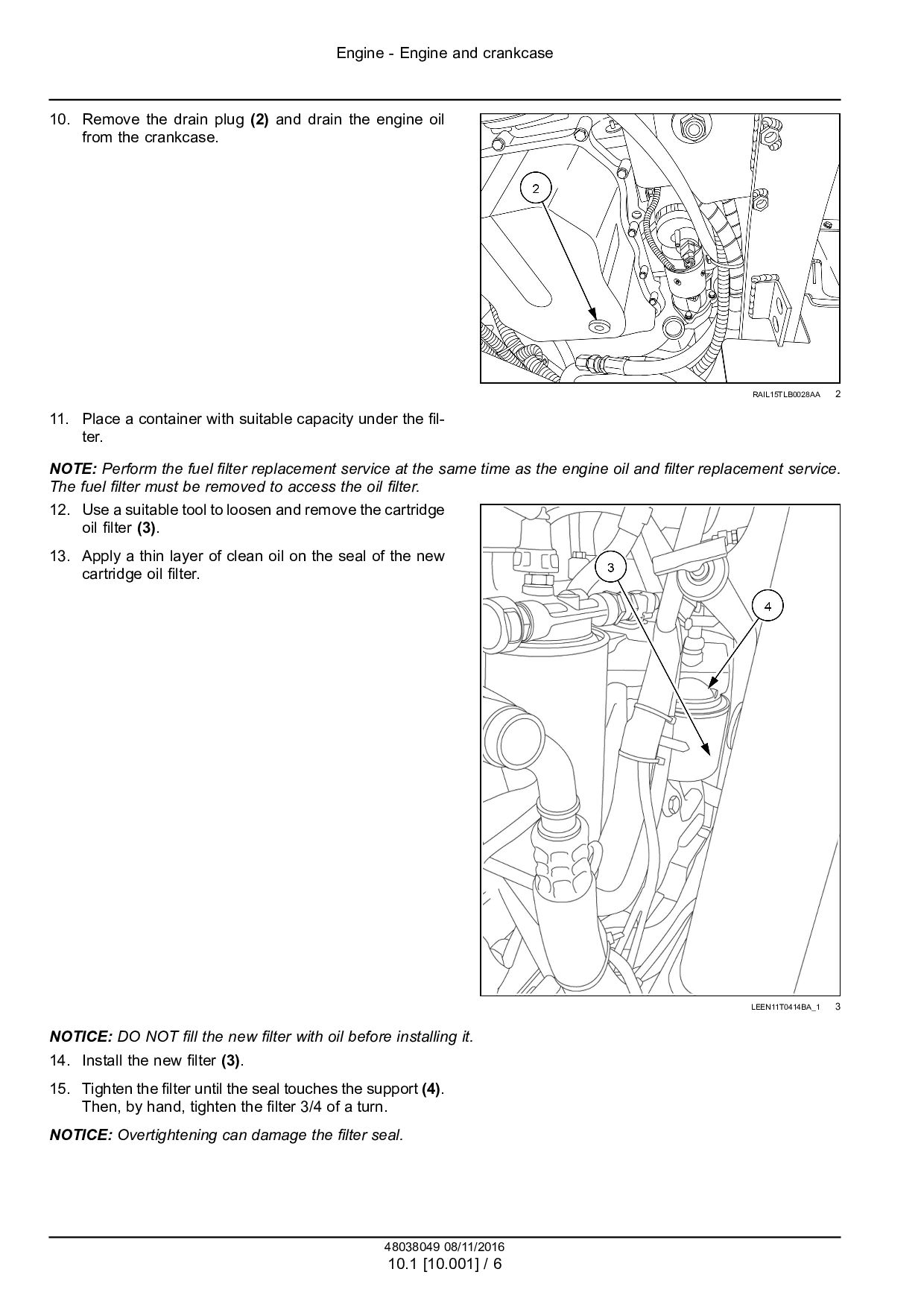
(2) and drain the engine oil from the crankcase. RAIL15TLB0028AA 2 11. Place a container with suitable capacity under the fil- ter. NOTE: Perform the fuel filter replacement service at the same time as the engine oil and filter replacement service. The fuel filter must be removed to access the oil filter. 12. Use a suitable tool to loosen and remove the cartridge oil filter (3). 13. Apply a thin layer of clean oil on the seal of the new cartridge oil filter. LEEN11T0414BA_1 3 NOTICE: DO NOT fill the new filter with oil before installing it. 14. Install the new filter (3). 15. Tighten the filter until the seal touches the support (4). Then, by hand, tighten the filter 3/4 of a turn. NOTICE: Overtightening can damage the filter seal. 48038049 08/11/2016 10.1 [10.001] / 6


 fjskkumdoksmk
 aleyda
 wjessup
 pauljervisheath
 greggifford
 jonrohan
 csswizardry
 tammyeverts
 watany
 michaelherold
 skipperchong
 morganepeng
 katarinadahlin