Upgrade to Pro — share decks privately, control downloads, hide ads and more …

2017-09-05-ifc-guidelines

Ken Arroyo Ohori
September 05, 2017
11k

 2017-09-05-ifc-guidelines

Ken Arroyo Ohori

September 05, 2017
Tweet

Transcript

  1. Recap: our goal and solution Develop an interface between CityGML

    and IFC to prepare for a fundamental solution to bridge the gap between Geo and BIM. 1. open-source API to represent IFC + CityGML with the same data structure 2. recommendations for future integration
  2. Found many issues & (some) solutions • Non-planar faces >

    triangulation • Non-closed objects > Nef polyhedra w/ Boolean set unions • Non-manifolds > Boolean set difference to remove parts • CGAL crashes > Catch error, slightly modify object and retry • Small gaps > Minkowski sum to close • Overlapping objects > Boolean set unions
  3. But some issues are more difficult to solve • Unsupported

    and problematic geometries create will create large gaps • Many geometries are labelled with generic classes • Self-intersections can’t be imported directly • Very large files can’t be processed with current workflow
  4. 1. Georeferencing • IfcSite can store RefLatitude, RefLongitude, RefElevation, LandTitleNumber

    and SiteAddress • IfcGeometricRepresentationContext can store a WorldCoordinateSystem, Precision and TrueNorth • Thus, in theory a point in the model can be georeferenced with precision….
  5. 1. Georeferencing • …But problems remain: • Positive values represent

    locations north of the equator, west of the geodetic zero meridian (nominally the Greenwich prime meridian) in IFC2x3, or east of the zero meridian in IFC4. • And above all, IfcSite is not properly used in practice. 3/3 of our test models are wrongly georeferenced.
  6. 1. Georeferencing • We therefore recommend that IFC files set

    their precise real-world location using the latitude, longitude and altitude values in the IfcSite taking into account the offset given by the WorldCoordinateSystem of the IfcGeometricRepresentationContext for the 3D model and the 2D plan (if used). • Due to practical difficulties, it cannot be expected that these values match the reality with the Precision given in the IfcGeometricRepresentationContext, but the values should be easy to set to within a few meters of the real location. • In addition, if the y-axis of the WorldCoordinateSystem in the IfcGeometricRepresentationContext does not match the true North direction, the TrueNorth attribute should be set as well.
  7. 2. Valid volumetric objects • Many possible ways to create

    inefficient or invalid objects: Boolean set operations that result in empty sets, invalid profiles in extrusions, b-rep shells that do not enclose a volume, self-intersecting topological manifolds, etc. • All these issues (and many more) are easy to generate, but they are rarely tested by software.
  8. 2. Valid volumetric objects • While all of the subtypes

    of IfcRepresentationItem have different uses, we recommend that practitioners use volumetric objects as much as possible, test that they conform to their entity definition and take care to make sure these are watertight when using b-rep representations.
  9. 3. No self-intersections or intersections between objects • IFC entities

    generally disallow self-intersections in their definition, such as the examples of IfcFacetedBrep and IfcFacetedBrepWithVoids. However, these sort of restrictions are easier to test with some entities than others and are often not enforced in software. • And to the best of our knowledge, the standard is not explicit about limiting intersections between objects and in practice most IFC files have small intersections between objects—sometimes below the model’s precision but sometimes above. • These kinds of intersections might not seem problematic when IFC models are only used for visualisation purposes, but they do harm more complex automated processing efforts.
  10. 3. No self-intersections or intersections between objects • We therefore

    recommend that users ensure that there are no self-intersections or intersections between objects, much like the BIM Basic IDM disallows intersections between objects by stating: ‘There are no duplicates or intersections permitted. Make sure this is checked in IFC.’
  11. 4. Forming enclosed spaces that are also modelled as IfcSpaces

    • While intersections between objects are undesirable, gaps between objects that are supposed to be adjacent are also a problem. Whereas BIM applications mostly focus on the built space, many Geo applications focus on the empty space between the built environment and the objects modelled in a BIM file, such as explicit rooms, hallways, stairways, and so on. • Because of the above, we recommend that all the necessary objects to form enclosed spaces should be modelled, and these objects should fit properly with each other and without gaps between them. • In addition, we recommend that enclosed spaces are also modelled explicitly and with their precise geometry as IfcSpaces.
  12. 5. Consistent use of the most specific entities possible •

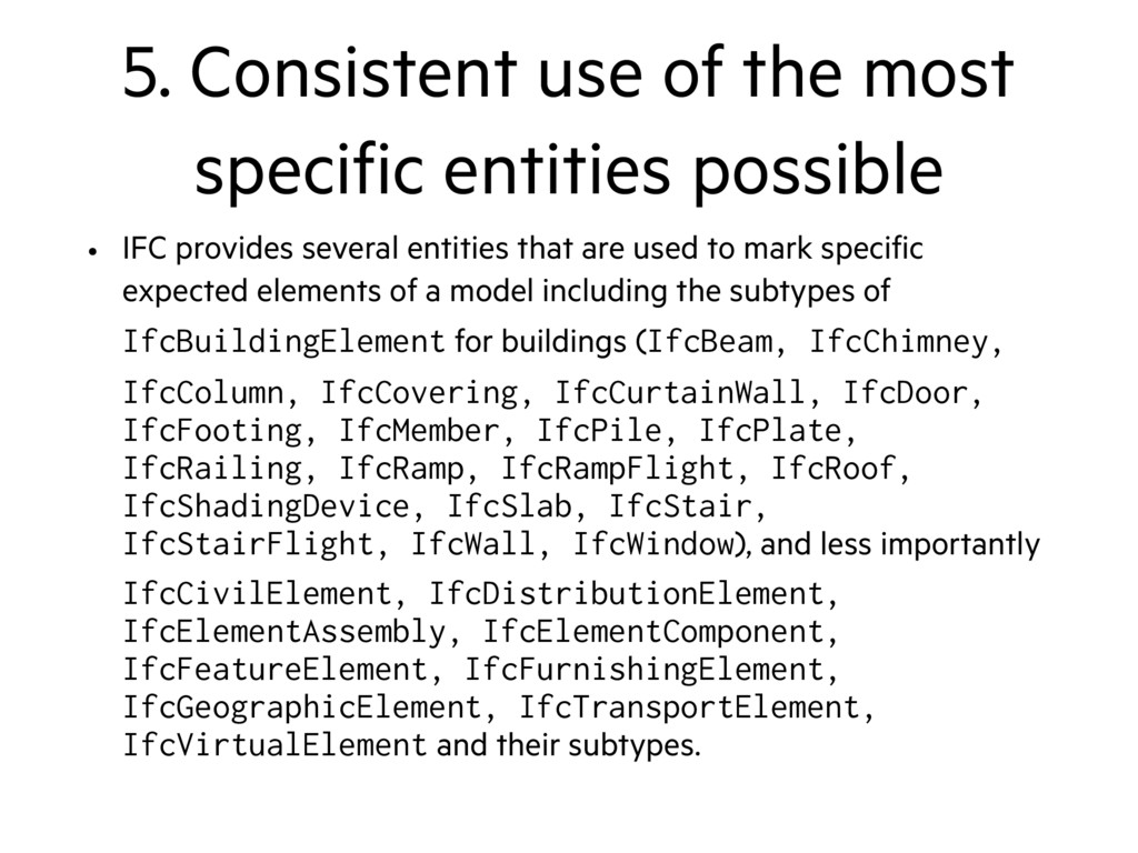
    IFC provides several entities that are used to mark specific expected elements of a model including the subtypes of IfcBuildingElement for buildings (IfcBeam, IfcChimney, IfcColumn, IfcCovering, IfcCurtainWall, IfcDoor, IfcFooting, IfcMember, IfcPile, IfcPlate, IfcRailing, IfcRamp, IfcRampFlight, IfcRoof, IfcShadingDevice, IfcSlab, IfcStair, IfcStairFlight, IfcWall, IfcWindow), and less importantly IfcCivilElement, IfcDistributionElement, IfcElementAssembly, IfcElementComponent, IfcFeatureElement, IfcFurnishingElement, IfcGeographicElement, IfcTransportElement, IfcVirtualElement and their subtypes.
  13. 5. Consistent use of the most specific entities possible •

    We have found a couple problems with the use of these entities: (i) they are not always used consistently between models (or even sometimes in a single model), and (ii) they often involve the use of the generic IfcBuildingElementProxy rather than one of the other more specific entities. • While both of these are minor problems when processing models manually, they make it needlessly difficult to do automated processing (eg deducing the correct entity types from names and descriptions). • We therefore recommend that users take care to always use the most specific entity type possible, to use such entity types consistently across all objects of a model, and to ensure that all related geometries of an object are marked as such.
  14. Other possible guidelines • A small geometric tolerance (IfcGeometricRepresentationContext.Precision) (eg

    preferably < 0.01 mm) and no geometries (e.g. cartesian trimmed curves, non- planar face loops, ...) with higher tolerances. • Use full digits for floating point serialisation. Preferably at least IEEE 754 double precision floating point numbers, eg up to 15 decimal places. • Use a similar geometric proximity for connected building elements. • Use explicit topological connectivity statements for connected elements, eg IfcRelConnectsPathElements.
  15. An observation • Complex IFC files (as they currently exist)

    are not very suited to automated processing. General complexity, errors in geometries and problems with tools all point in that direction.
  16. Next steps • Now, write final report with final IFC

    guidelines. • Future work? • Find out how to best follow guidelines in software • Tackle identified issues (eg closing gaps and recovering from more invalid objects) • Reconstruction approach towards IFC processing • Other ideas?