in Building and Scaling Mobile Products. Tech Writer, Open Source Contributor & CS Researcher. Contributed in digitalisation of KPK Police. Active tech speaker and has delivered many talks at national and international venues. About Me Development Techniques UML Summary
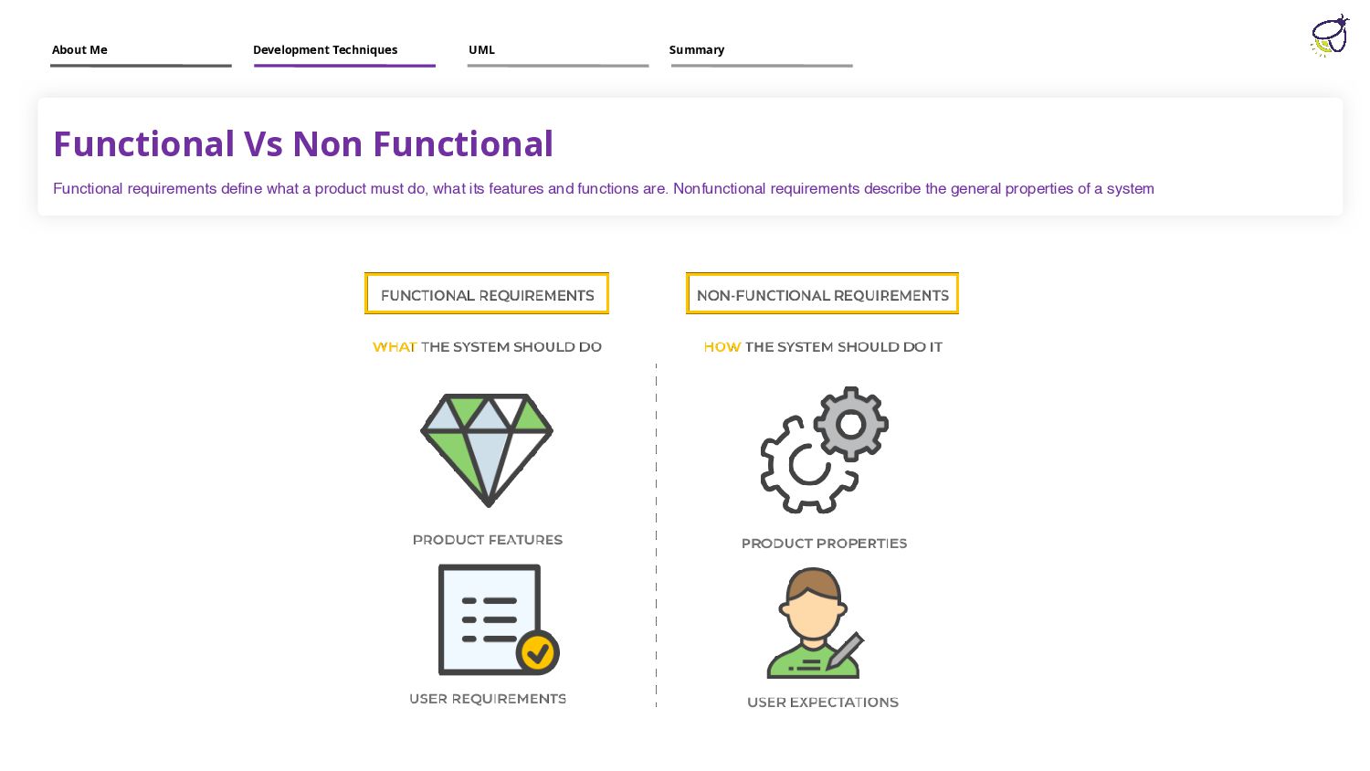
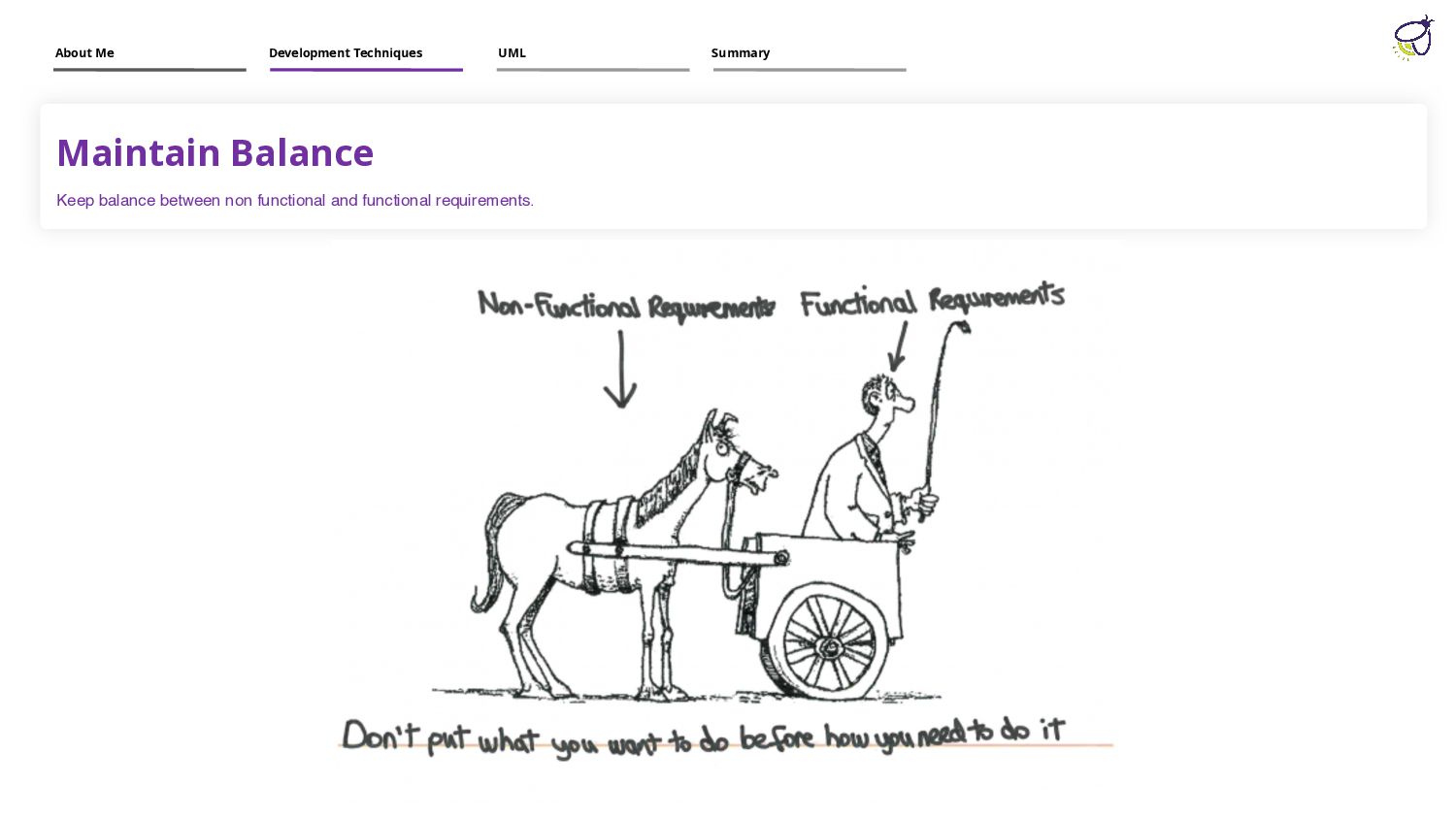
must do, what its features and functions are. Nonfunctional requirements describe the general properties of a system About Me Development Techniques UML Summary
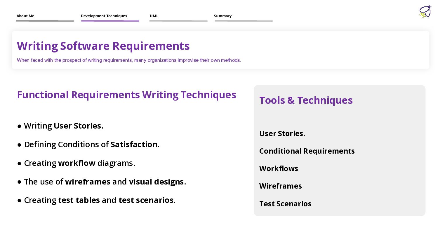
requirements, many organizations improvise their own methods. Functional Requirements Writing Techniques • Writing User Stories. • Defining Conditions of Satisfaction. • Creating workflow diagrams. • The use of wireframes and visual designs. • Creating test tables and test scenarios. Tools & Techniques User Stories. Conditional Requirements Workflows Wireframes Test Scenarios About Me Development Techniques UML Summary
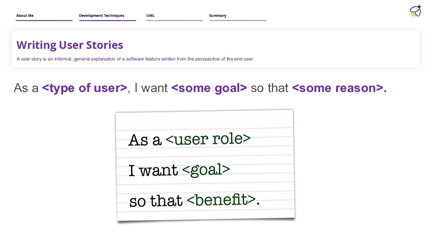
explanation of a software feature written from the perspective of the end user. As a <type of user>, I want <some goal> so that <some reason>. About Me Development Techniques UML Summary
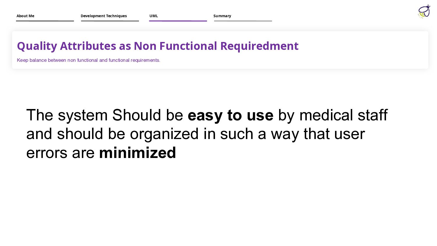
functional and functional requirements. The system Should be easy to use by medical staff and should be organized in such a way that user errors are minimized About Me Development Techniques UML Summary
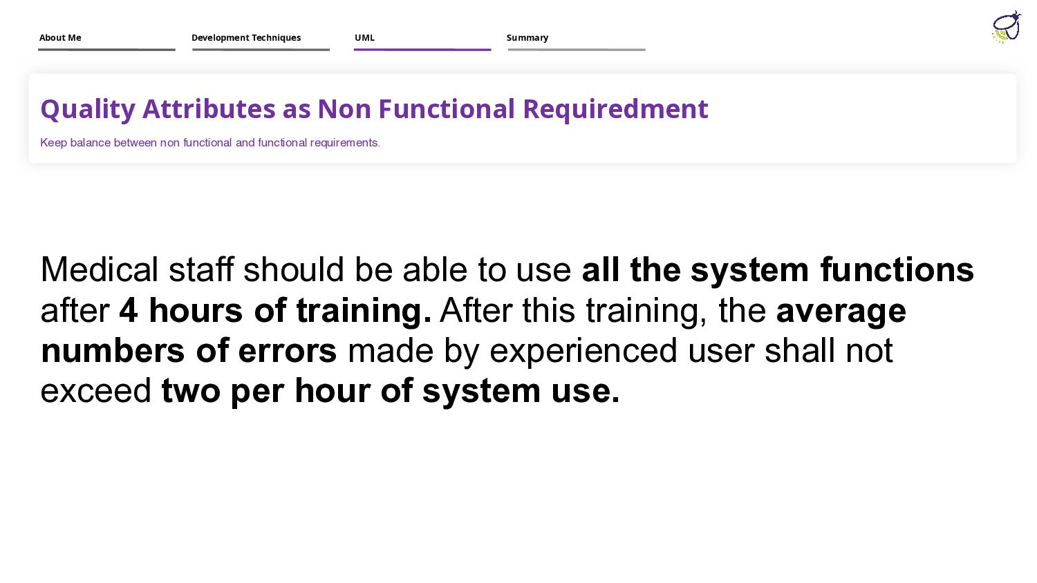
functional and functional requirements. Medical staff should be able to use all the system functions after 4 hours of training. After this training, the average numbers of errors made by experienced user shall not exceed two per hour of system use. About Me Development Techniques UML Summary
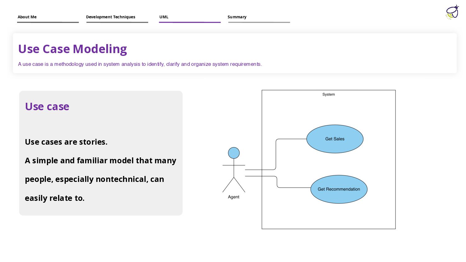
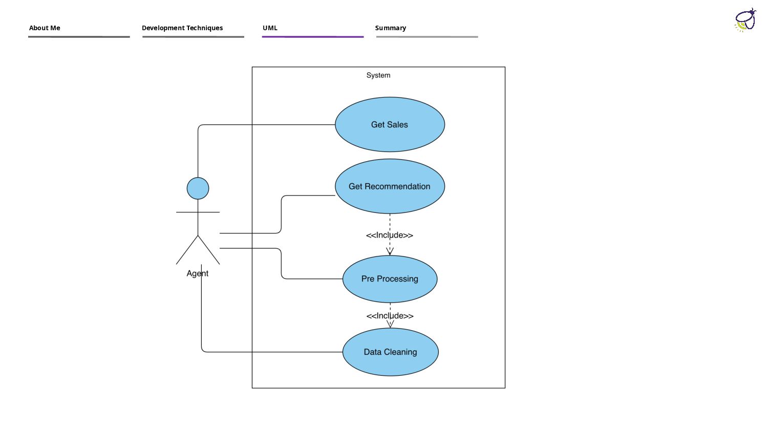
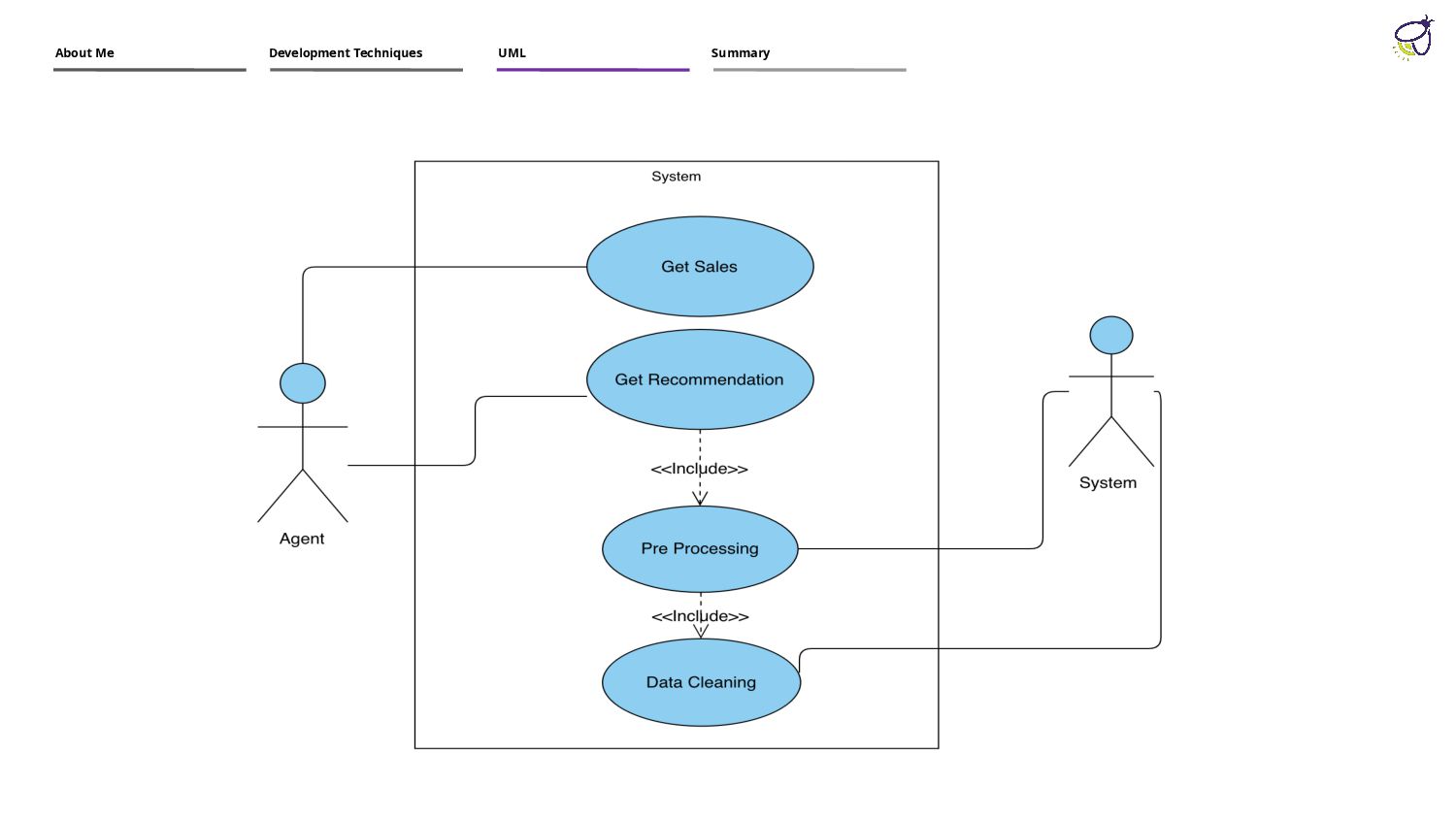
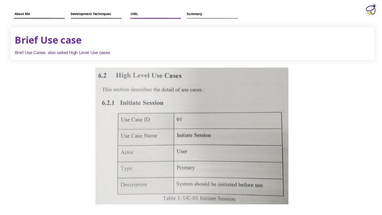
in system analysis to identify, clarify and organize system requirements. Use case Use cases are stories. A simple and familiar model that many people, especially nontechnical, can easily relate to. About Me Development Techniques UML Summary
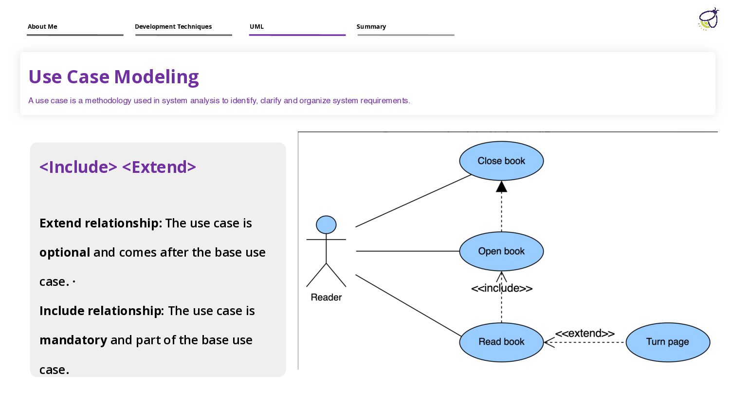
in system analysis to identify, clarify and organize system requirements. <Include> <Extend> Extend relationship: The use case is optional and comes after the base use case. · Include relationship: The use case is mandatory and part of the base use case. About Me Development Techniques UML Summary
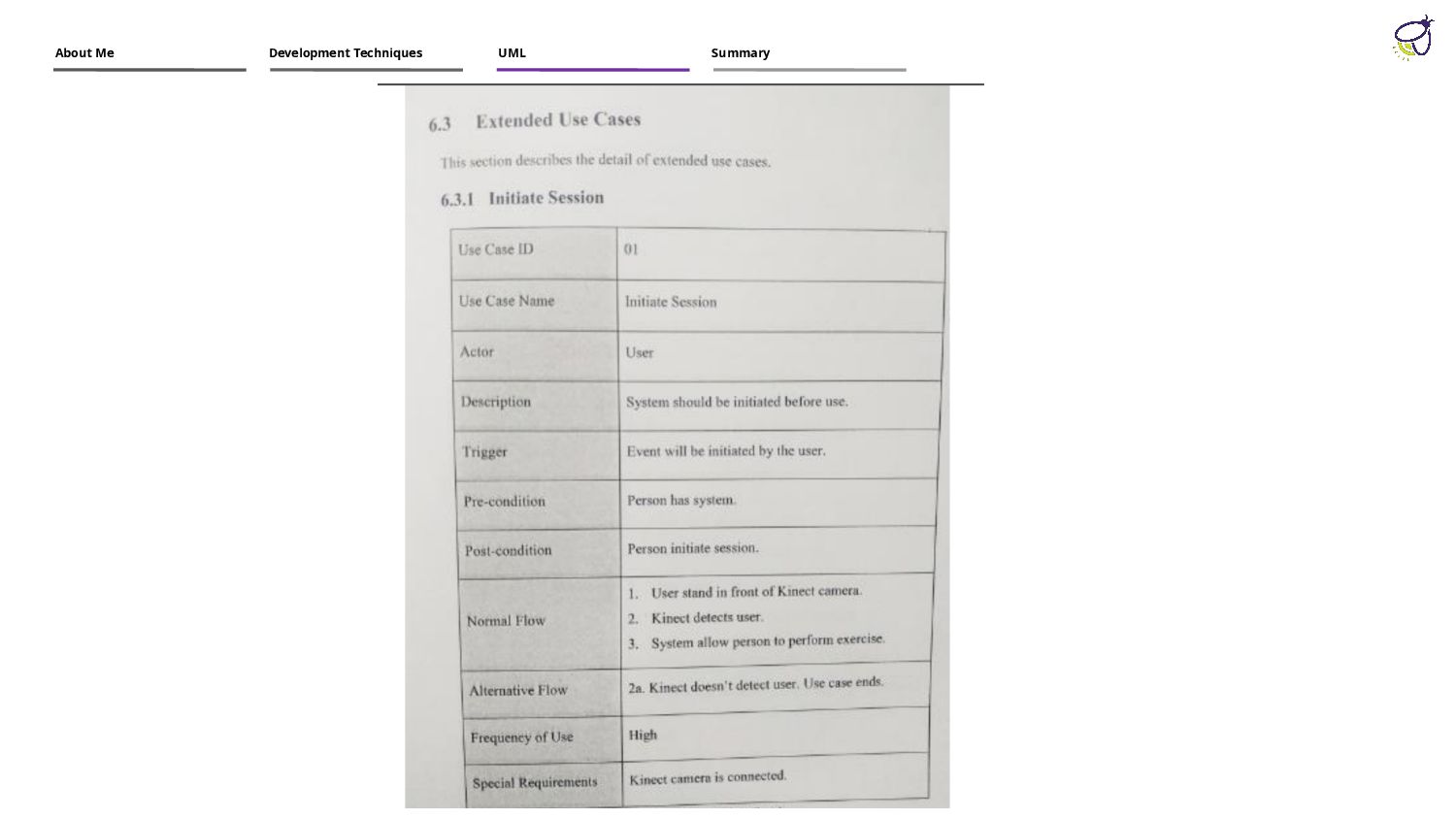
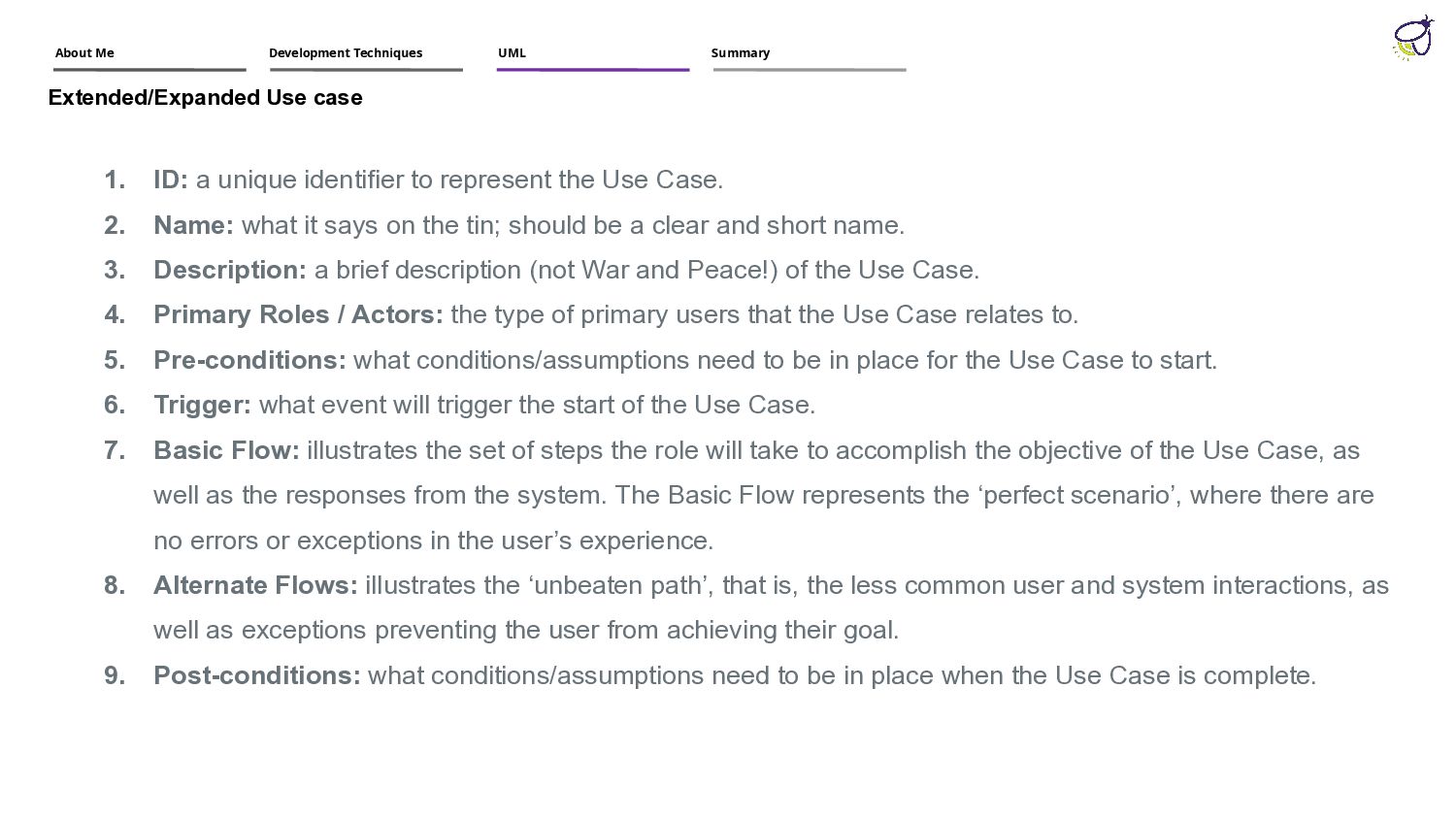
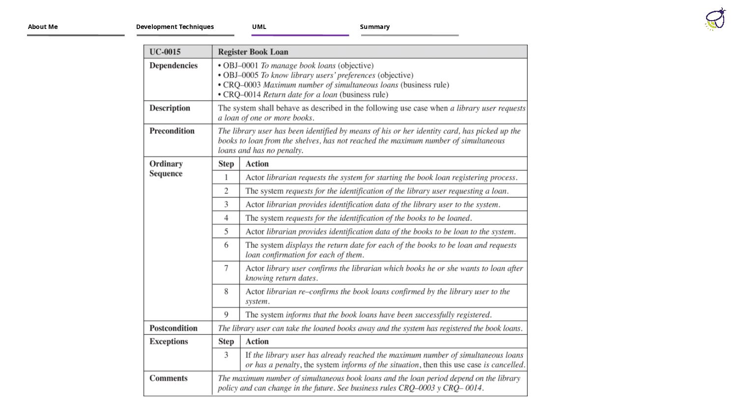
2. Name: what it says on the tin; should be a clear and short name. 3. Description: a brief description (not War and Peace!) of the Use Case. 4. Primary Roles / Actors: the type of primary users that the Use Case relates to. 5. Pre-conditions: what conditions/assumptions need to be in place for the Use Case to start. 6. Trigger: what event will trigger the start of the Use Case. 7. Basic Flow: illustrates the set of steps the role will take to accomplish the objective of the Use Case, as well as the responses from the system. The Basic Flow represents the ‘perfect scenario’, where there are no errors or exceptions in the user’s experience. 8. Alternate Flows: illustrates the ‘unbeaten path’, that is, the less common user and system interactions, as well as exceptions preventing the user from achieving their goal. 9. Post-conditions: what conditions/assumptions need to be in place when the Use Case is complete. Extended/Expanded Use case About Me Development Techniques UML Summary
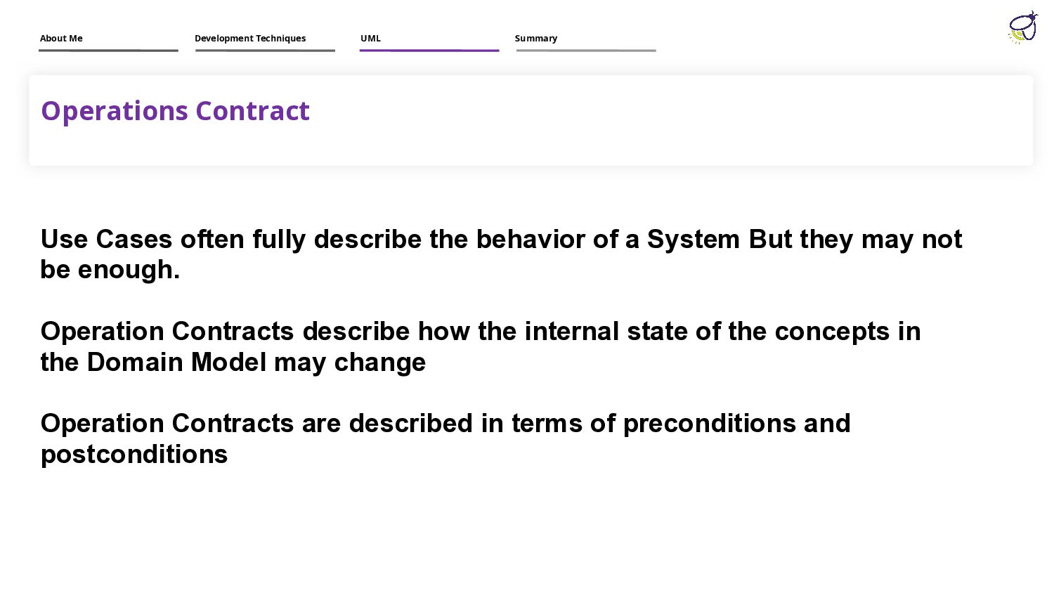
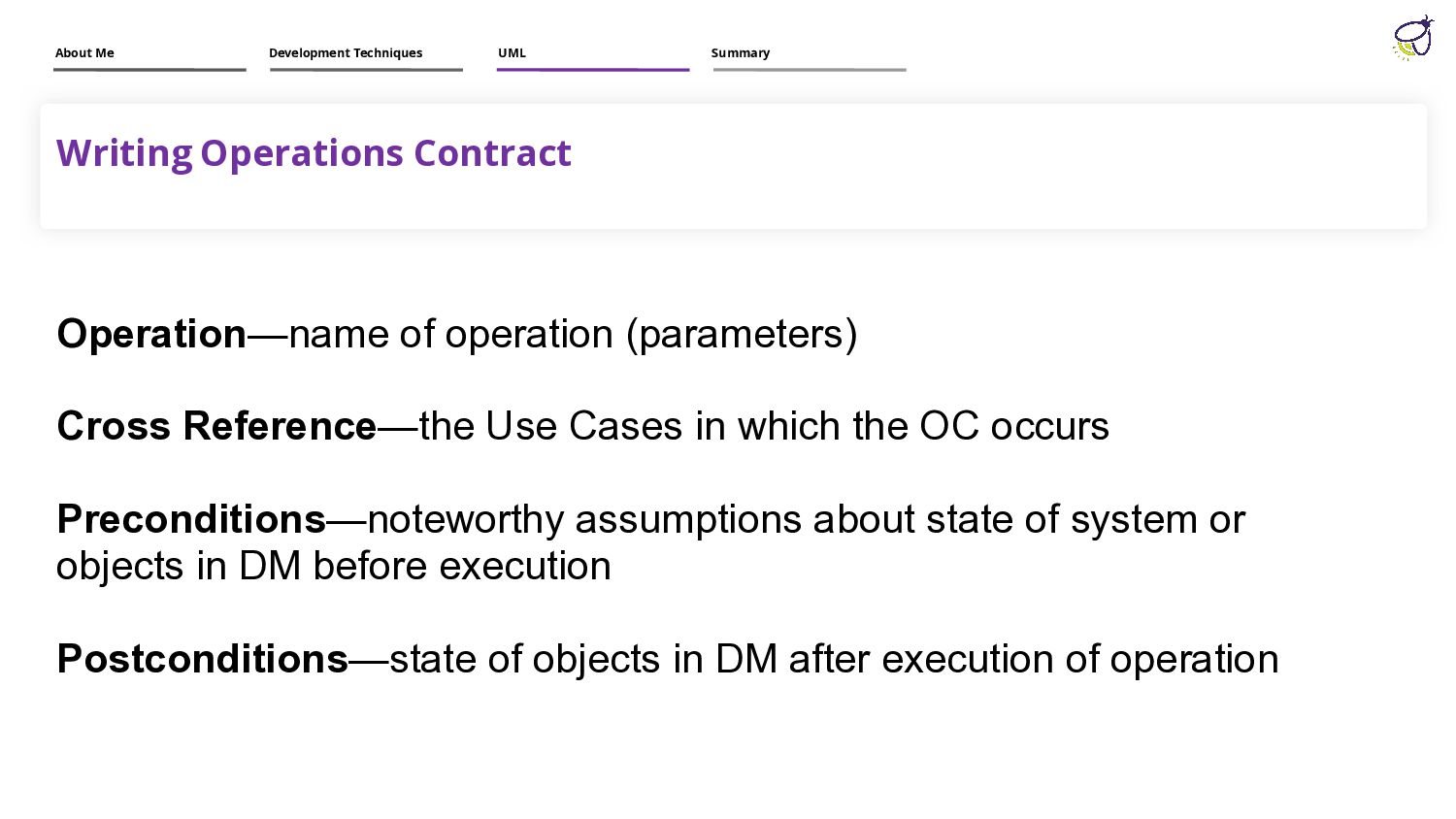
a System But they may not be enough. Operation Contracts describe how the internal state of the concepts in the Domain Model may change Operation Contracts are described in terms of preconditions and postconditions About Me Development Techniques UML Summary
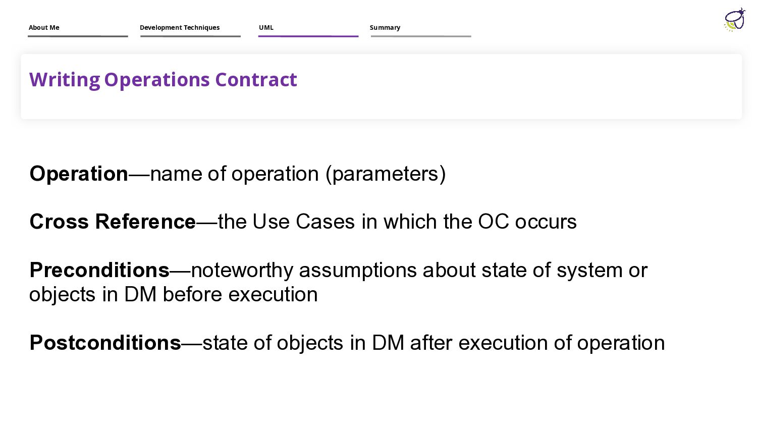
Cases in which the OC occurs Preconditions—noteworthy assumptions about state of system or objects in DM before execution Postconditions—state of objects in DM after execution of operation About Me Development Techniques UML Summary
Cases in which the OC occurs Preconditions—noteworthy assumptions about state of system or objects in DM before execution Postconditions—state of objects in DM after execution of operation About Me Development Techniques UML Summary
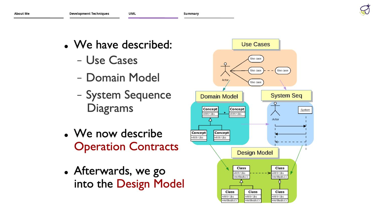
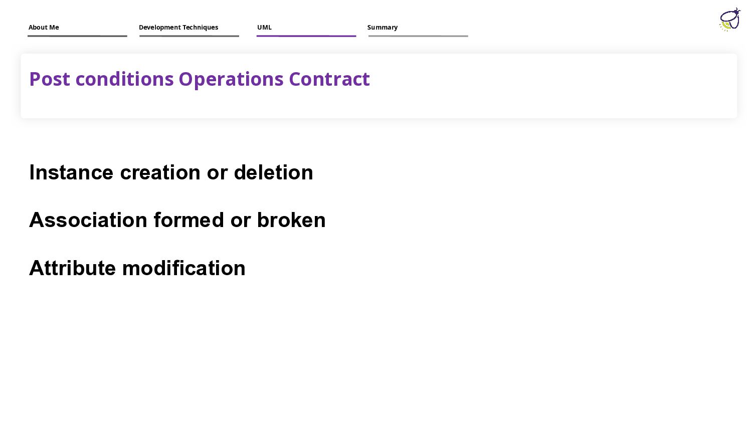
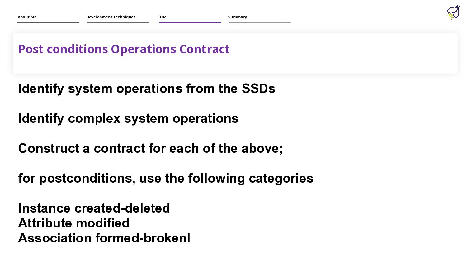
Identify complex system operations Construct a contract for each of the above; for postconditions, use the following categories Instance created-deleted Attribute modified Association formed-brokenI About Me Development Techniques UML Summary
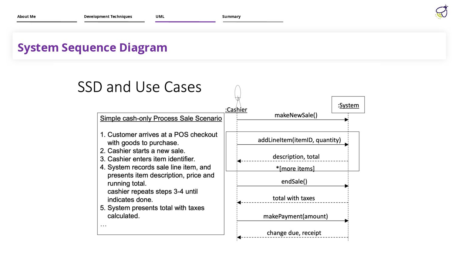
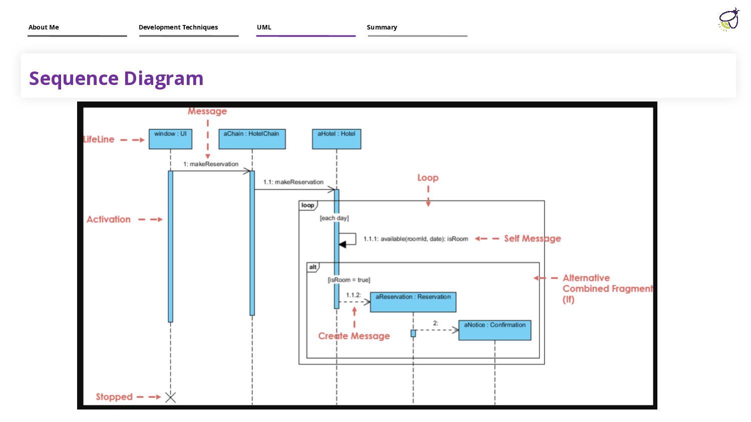
• The horizontal axis shows the elements that are involved in the interaction • Conventionally, the objects involved in the operation are listed from left to right according to when they take part in the message sequence. However, the elements on the horizontal axis may appear in any order Time Dimension The vertical axis represents time proceedings (or progressing) down the page. Note that: Time in a sequence diagram is all a about ordering, not duration. The vertical space in an interaction diagram is
• The horizontal axis shows the elements that are involved in the interaction • Conventionally, the objects involved in the operation are listed from left to right according to when they take part in the message sequence. However, the elements on the horizontal axis may appear in any order Time Dimension The vertical axis represents time proceedings (or progressing) down the page. Note that: Time in a sequence diagram is all a about ordering, not duration. The vertical space in an interaction diagram is
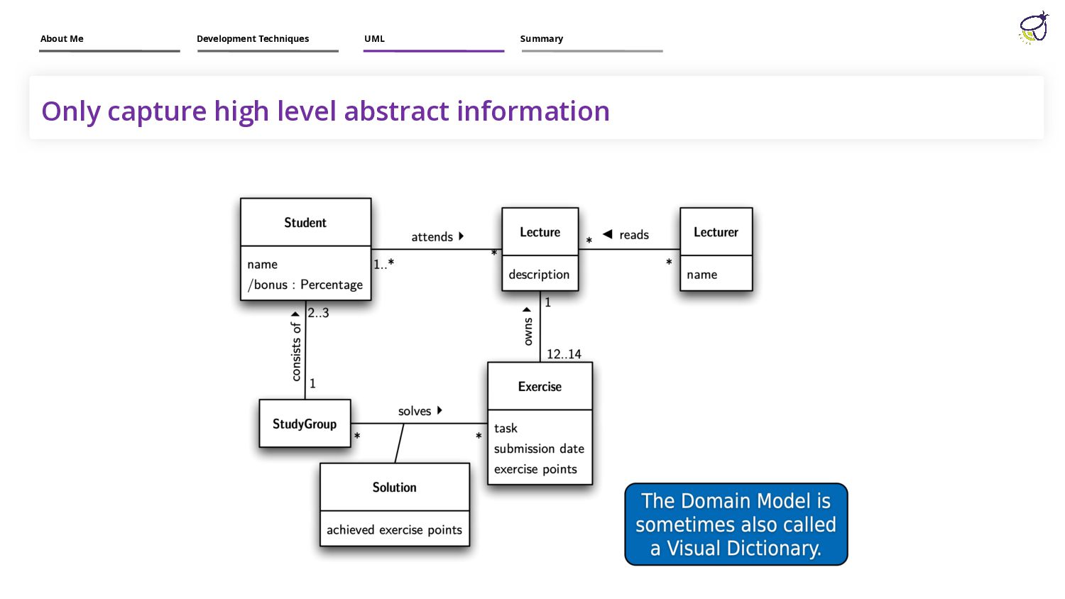
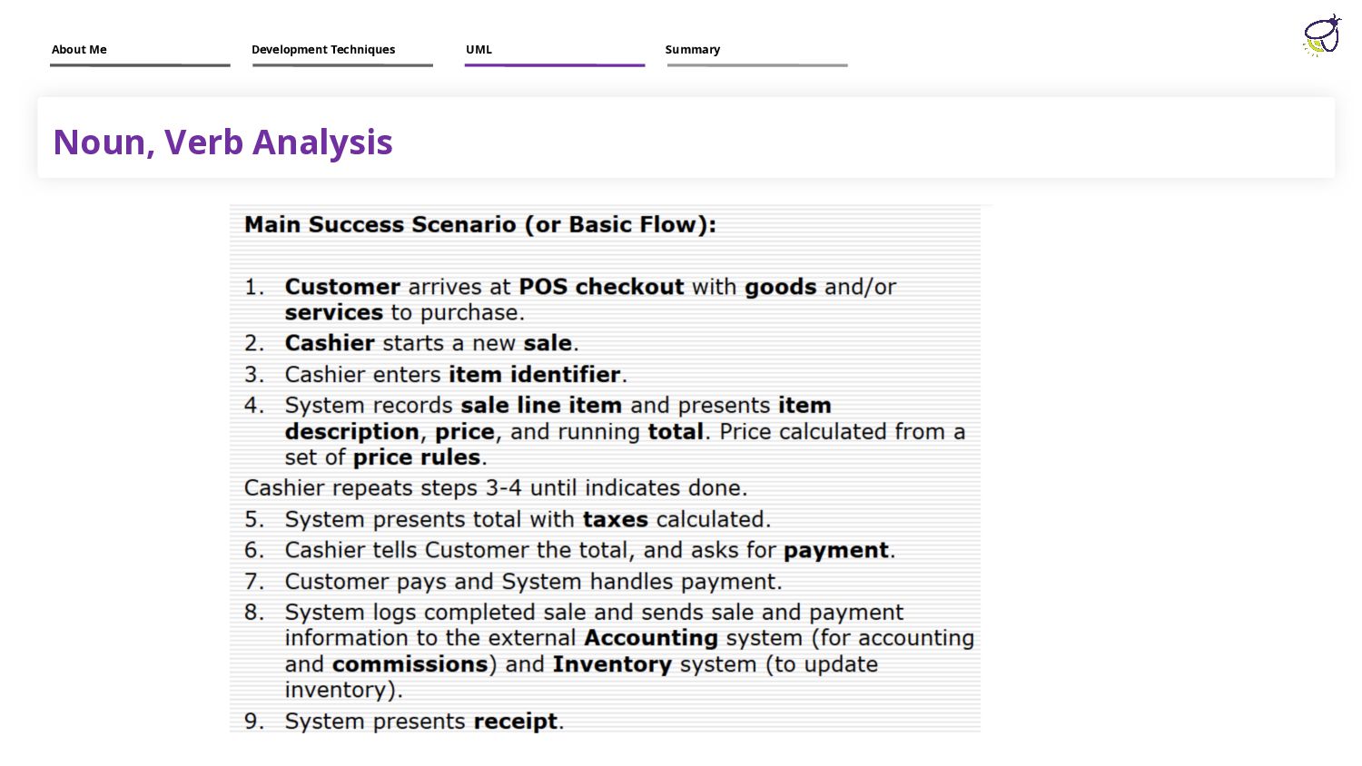
activity of finding out which concepts are important to our system. This process helps us to understand the problem further, and develop a better awareness of our customer’s business About Me Development Techniques UML Summary
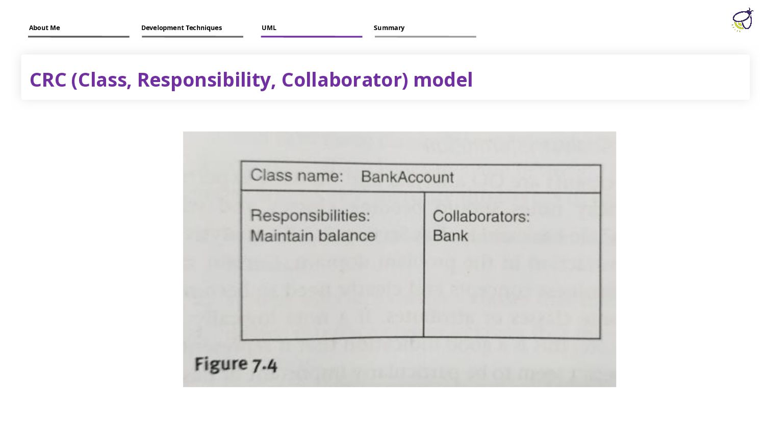
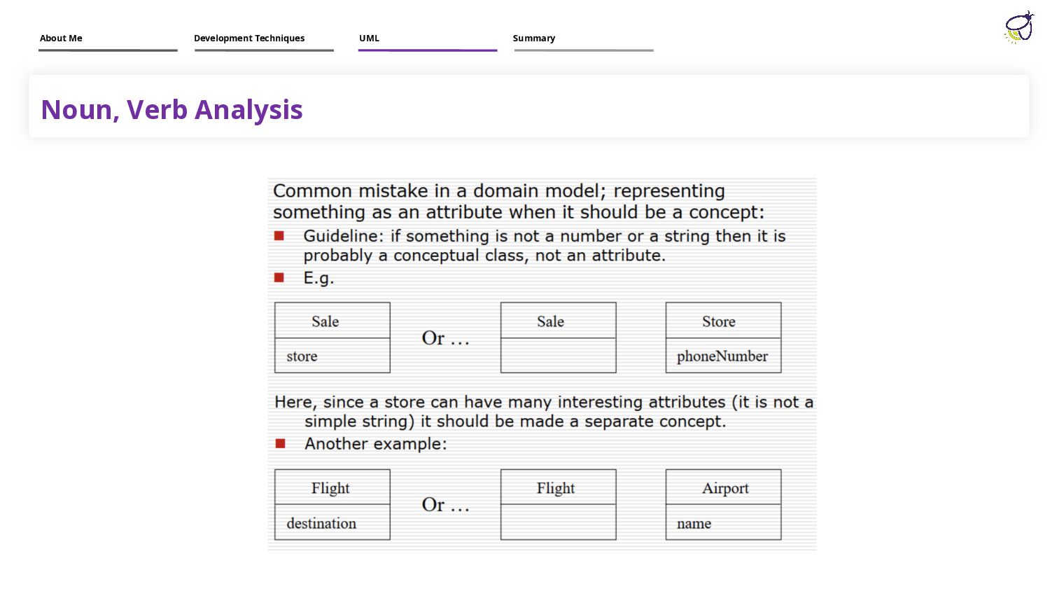
the problem, it shows: domain objects or conceptual classes associations between conceptual classes attributes of conceptual classes A domain model does not represent software classes : no artificial, programming-related (e.g. interface classes), About Me Development Techniques UML Summary
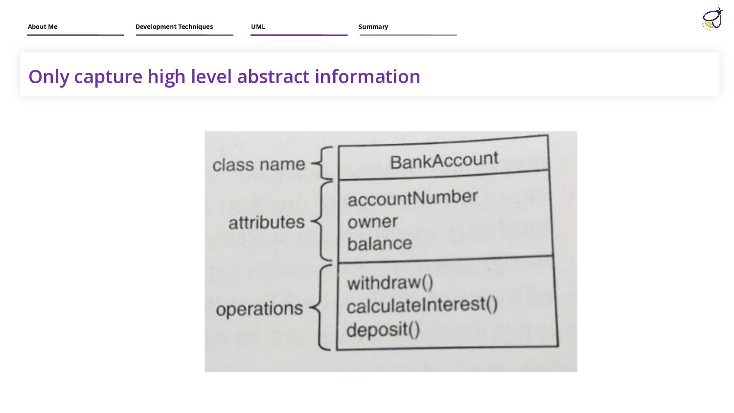
types of diagrams in UML as they clearly map out the structure of a particular system by modeling its classes, attributes, operations, and relationships between objects. About Me Development Techniques UML Summary
code. We can use them at three different levels. Real world projects may have thousands of classes. How can we display all of them in class diagram? About Me Development Techniques UML Summary
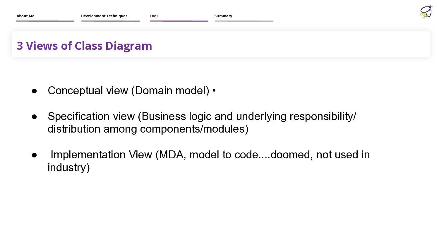
logic and underlying responsibility/ distribution among components/modules) • Implementation View (MDA, model to code....doomed, not used in industry) 3 Views of Class Diagram About Me Development Techniques UML Summary
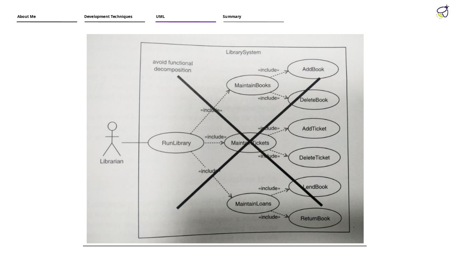
in Use case diagrams. Do: (Only capture features to be exposed to users and focus on user goals only). CRUD operations add, read, update, delete etc should not be captured too. Focus on high level objective like manage user profiles Operational contracts format violation, Specifically post condition is neglected. Do: (Identify system operations from the SSDs, Then shortlist subtle or complex system operations, then make contract for them. Don’t forget DM’s relation with Ocs. Post condition must contain Instance created- deleted, Attribute modified, Association formedbroken
for every use case. Do: SSD for brief use case is not required. Operation signatures are not complete in class diagram. Class Diagram & Sequence diagram are not synchronized. Do: Classes in Class diagram, must be instantiated in sequence diagram. Provide complete detail of return types, parameters etc in OS


 abidjamil
 a_matsuda
 suneo3476
 satoshi256kbyte
 akihisaikeda
 falcon8823
 uyuki234
 oniak3ibm
 ___akari11
 marcoroth
 neuecc
 rollbear
 deanohume
 codingconduct
 sarafernandez
 thirion
 rasagy
 jct
jct
 mza
mza
 jcasabona
 axbom
axbom
 sachag
 erikaheidi
 tonyrice