2014 Pre-MSc-IS-0 Information Systems Modelling and Design
Programme: Master of Science in Business Information Systems FHNW
Course: Pre-Master Information Systems
Topic: Information Systems Modelling and Design
Information Systems FHNW Pre-Master Information Systems Information Systems Modelling and Design Andreas Martin Information Systems Modelling and Design http://www.flickr.com/photos/dirk_hofmann/4200450207
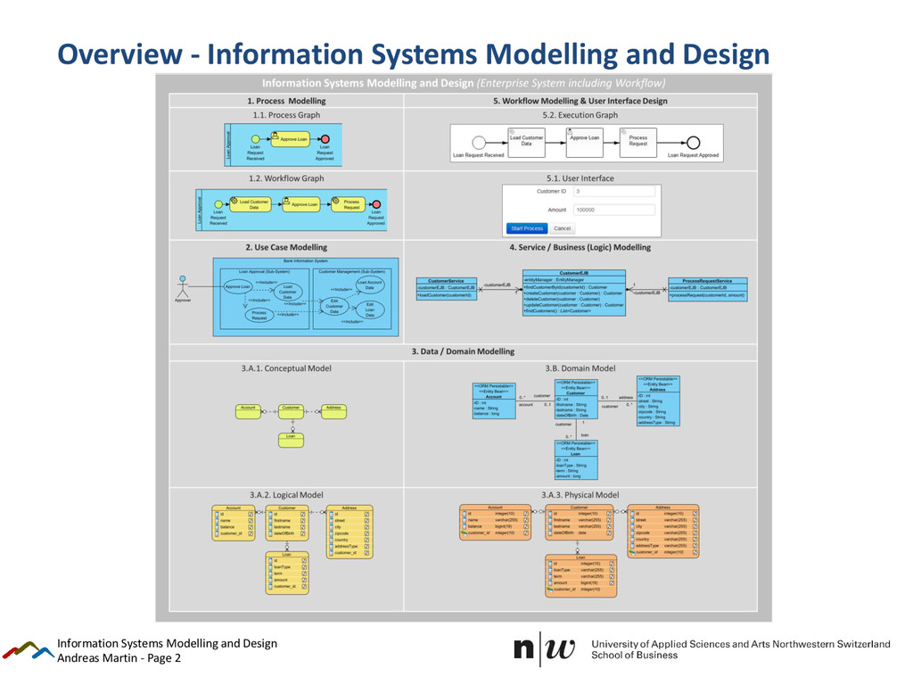
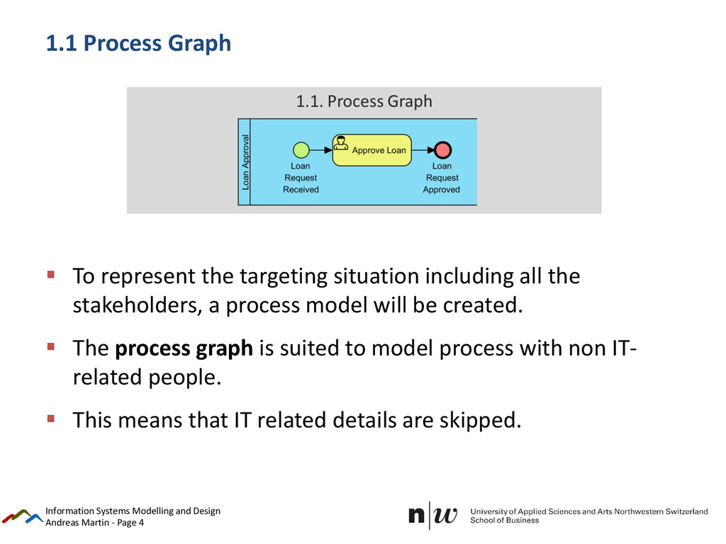
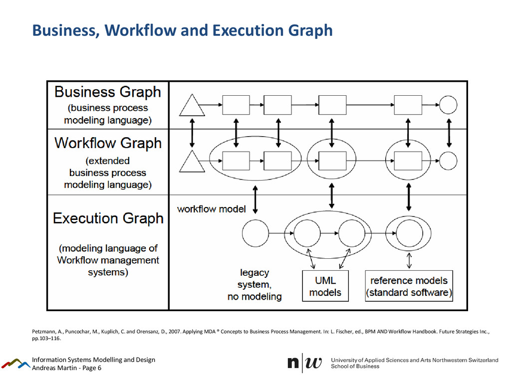
represent the targeting situation including all the stakeholders, a process model will be created. The process graph is suited to model process with non IT- related people. This means that IT related details are skipped. Information Systems Modelling and Design
Information Systems Modelling and Design Petzmann, A., Puncochar, M., Kuplich, C. and Orensanz, D., 2007. Applying MDA ® Concepts to Business Process Management. In: L. Fischer, ed., BPM AND Workflow Handbook. Future Strategies Inc., pp.103–116.
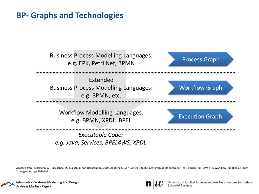
Systems Modelling and Design Business Process Modelling Languages: e.g. EPK, Petri Net, BPMN Extended Business Process Modelling Languages: e.g. BPMN, etc. Workflow Modelling Languages: e.g. BPMN, XPDL, BPEL Executable Code: e.g. Java, Services, BPEL4WS, XPDL Process Graph Workflow Graph Execution Graph Adapted from: Petzmann, A., Puncochar, M., Kuplich, C. and Orensanz, D., 2007. Applying MDA ® Concepts to Business Process Management. In: L. Fischer, ed., BPM AND Workflow Handbook. Future Strategies Inc., pp.103–116.
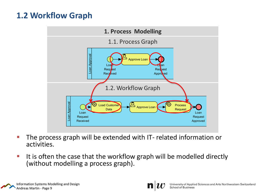
process graph will be extended with IT- related information or activities. It is often the case that the workflow graph will be modelled directly (without modelling a process graph). Information Systems Modelling and Design
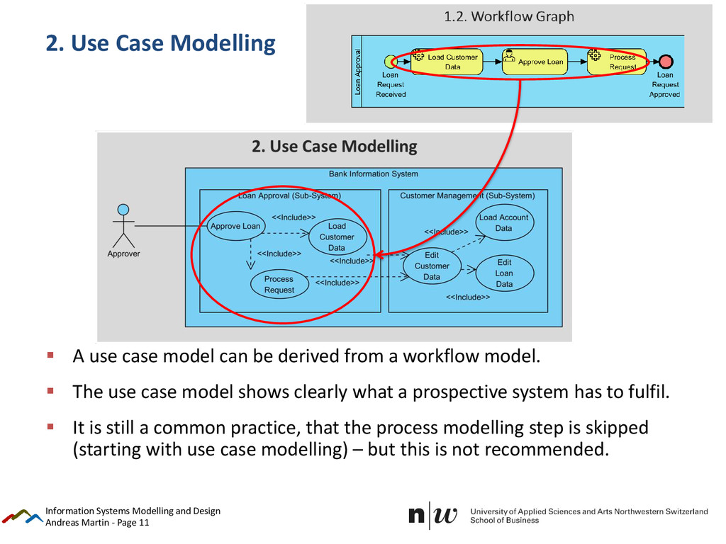
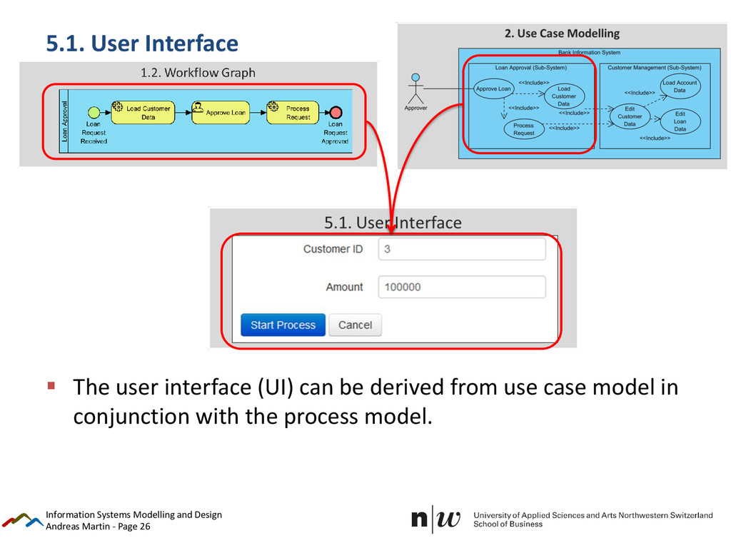
A use case model can be derived from a workflow model. The use case model shows clearly what a prospective system has to fulfil. It is still a common practice, that the process modelling step is skipped (starting with use case modelling) – but this is not recommended. Information Systems Modelling and Design
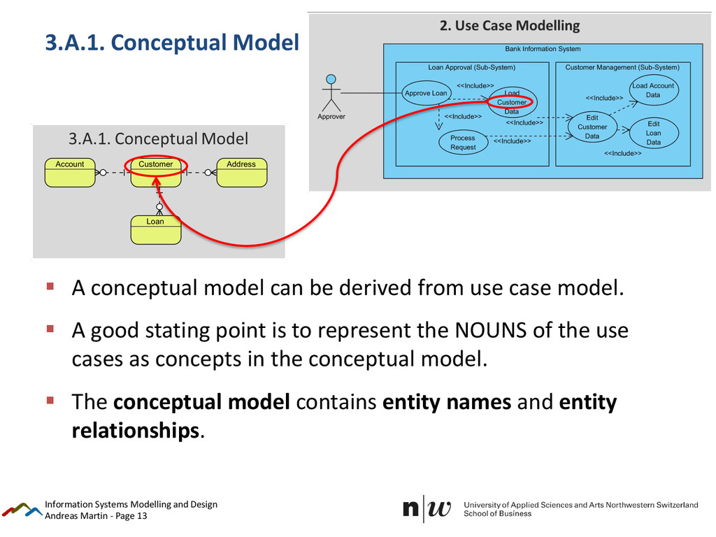
conceptual model can be derived from use case model. A good stating point is to represent the NOUNS of the use cases as concepts in the conceptual model. The conceptual model contains entity names and entity relationships. Information Systems Modelling and Design
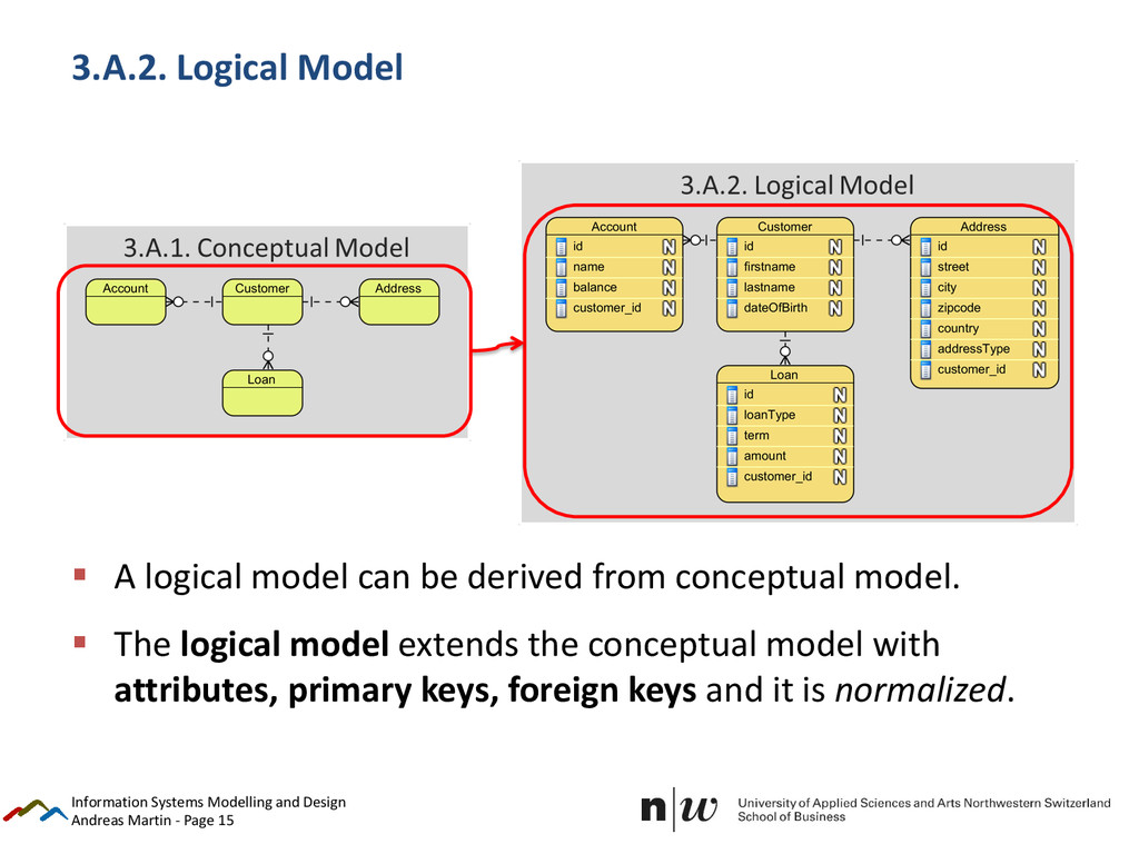
logical model can be derived from conceptual model. The logical model extends the conceptual model with attributes, primary keys, foreign keys and it is normalized. Information Systems Modelling and Design
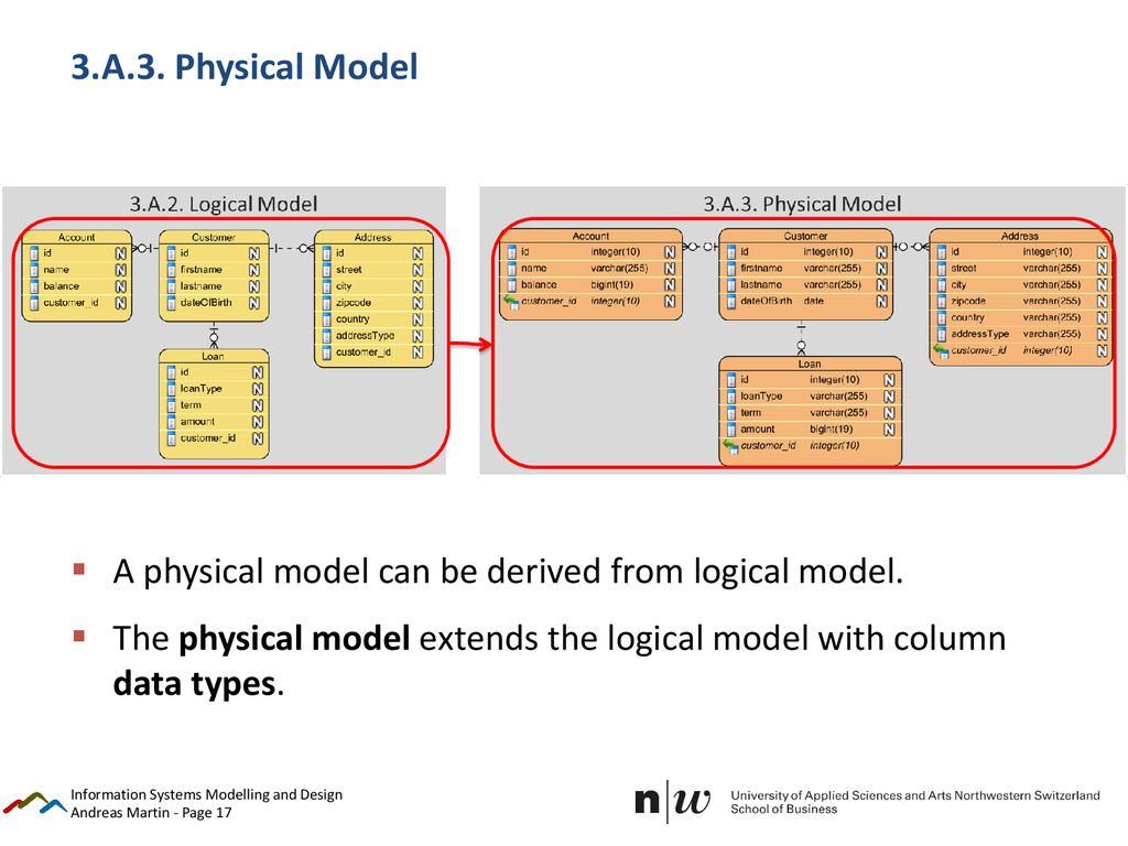
physical model can be derived from logical model. The physical model extends the logical model with column data types. Information Systems Modelling and Design
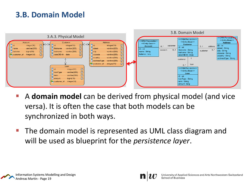
domain model can be derived from physical model (and vice versa). It is often the case that both models can be synchronized in both ways. The domain model is represented as UML class diagram and will be used as blueprint for the persistence layer. Information Systems Modelling and Design
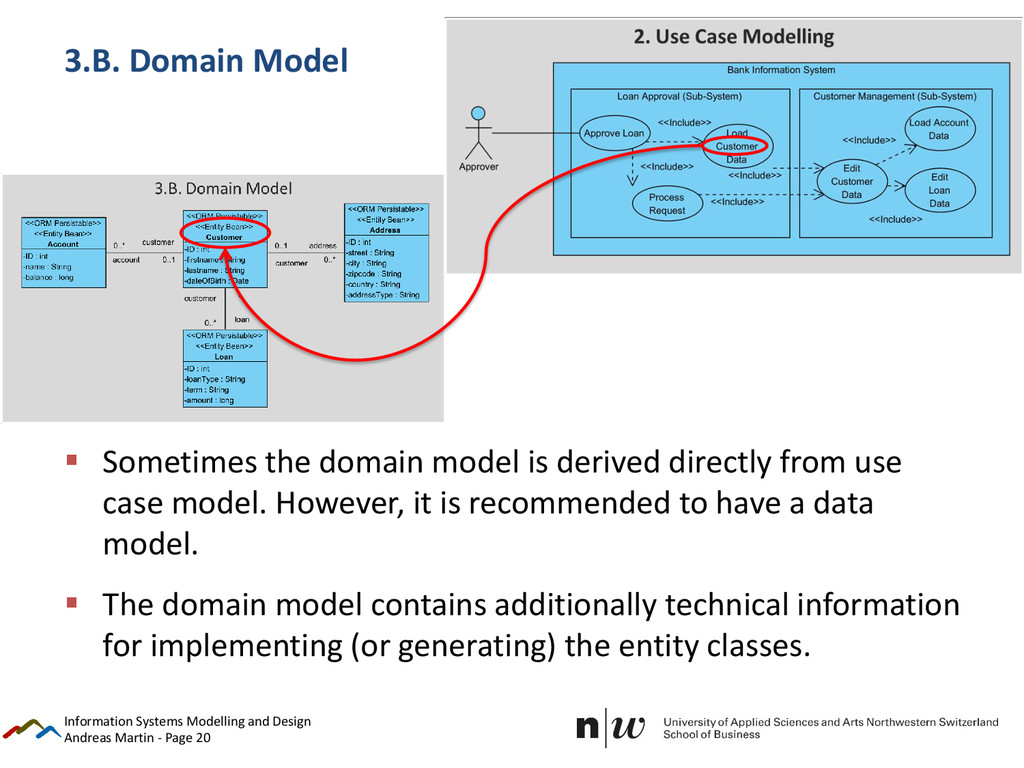
the domain model is derived directly from use case model. However, it is recommended to have a data model. The domain model contains additionally technical information for implementing (or generating) the entity classes. Information Systems Modelling and Design
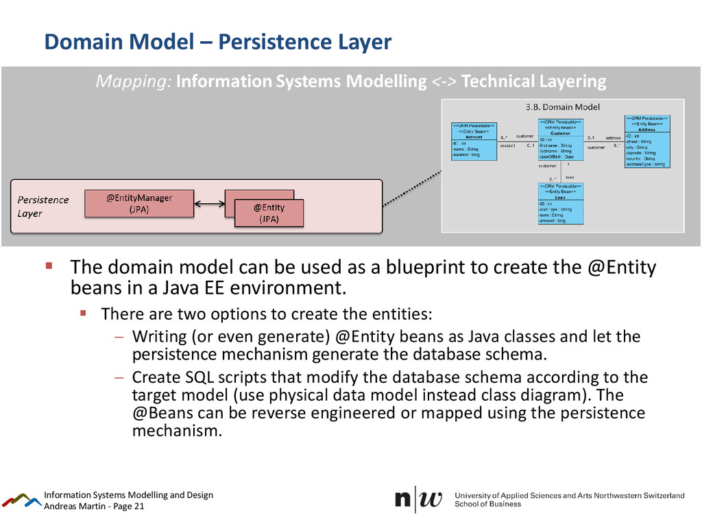
The domain model can be used as a blueprint to create the @Entity beans in a Java EE environment. There are two options to create the entities: Writing (or even generate) @Entity beans as Java classes and let the persistence mechanism generate the database schema. Create SQL scripts that modify the database schema according to the target model (use physical data model instead class diagram). The @Beans can be reverse engineered or mapped using the persistence mechanism. Information Systems Modelling and Design
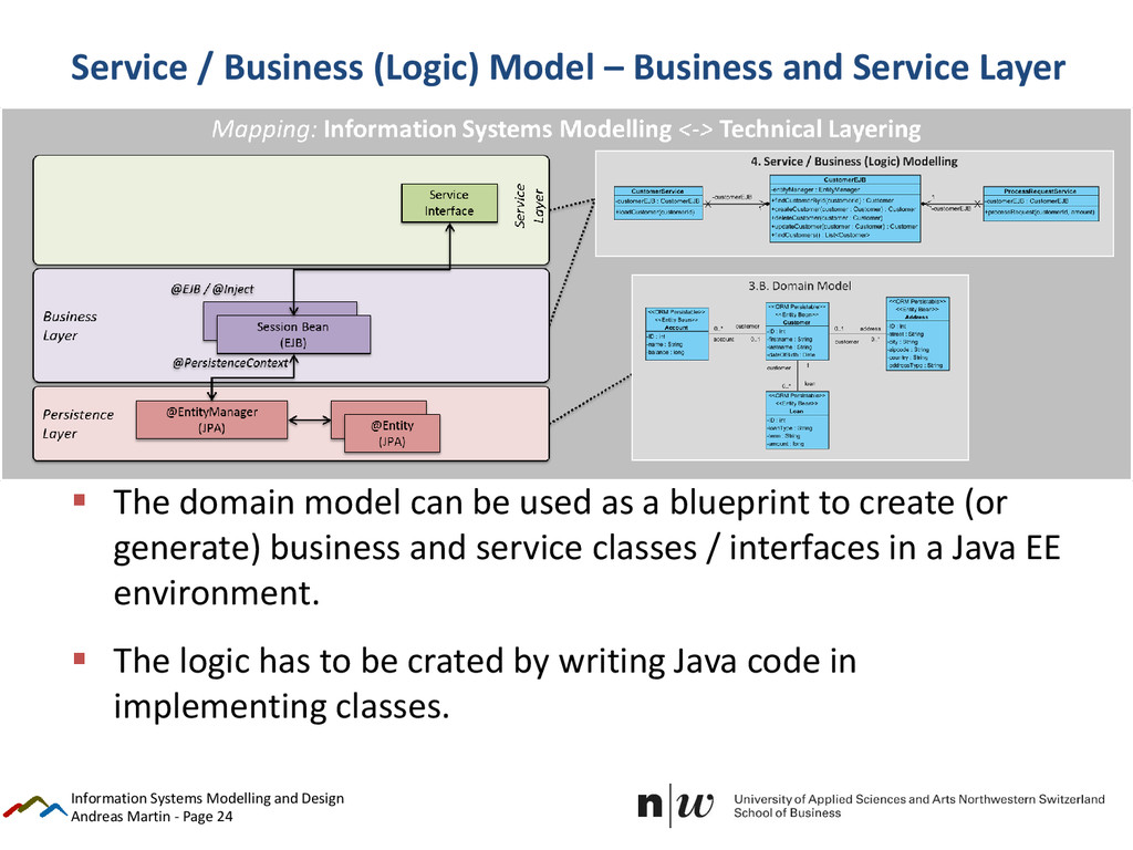
Modelling A service / business (logic) model can be derived from use case model. A good stating point is to represent the VERBS (incl. NOUNS) of the use cases as methods. Sometimes the business (logic) and the services will be modelled in separated models – it depends on the size of the project and the chosen system layering. Information Systems Modelling and Design
– Business and Service Layer The domain model can be used as a blueprint to create (or generate) business and service classes / interfaces in a Java EE environment. The logic has to be crated by writing Java code in implementing classes. Information Systems Modelling and Design
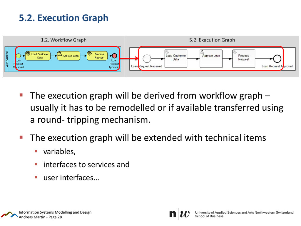
execution graph will be derived from workflow graph – usually it has to be remodelled or if available transferred using a round- tripping mechanism. The execution graph will be extended with technical items variables, interfaces to services and user interfaces… Information Systems Modelling and Design
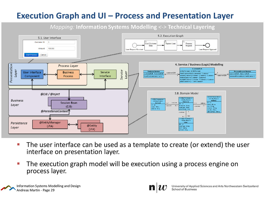
Process and Presentation Layer The user interface can be used as a template to create (or extend) the user interface on presentation layer. The execution graph model will be execution using a process engine on process layer. Information Systems Modelling and Design