Upgrade to Pro — share decks privately, control downloads, hide ads and more …

Vom Widerstand Zum Arduino

Vom Widerstand Zum Arduino

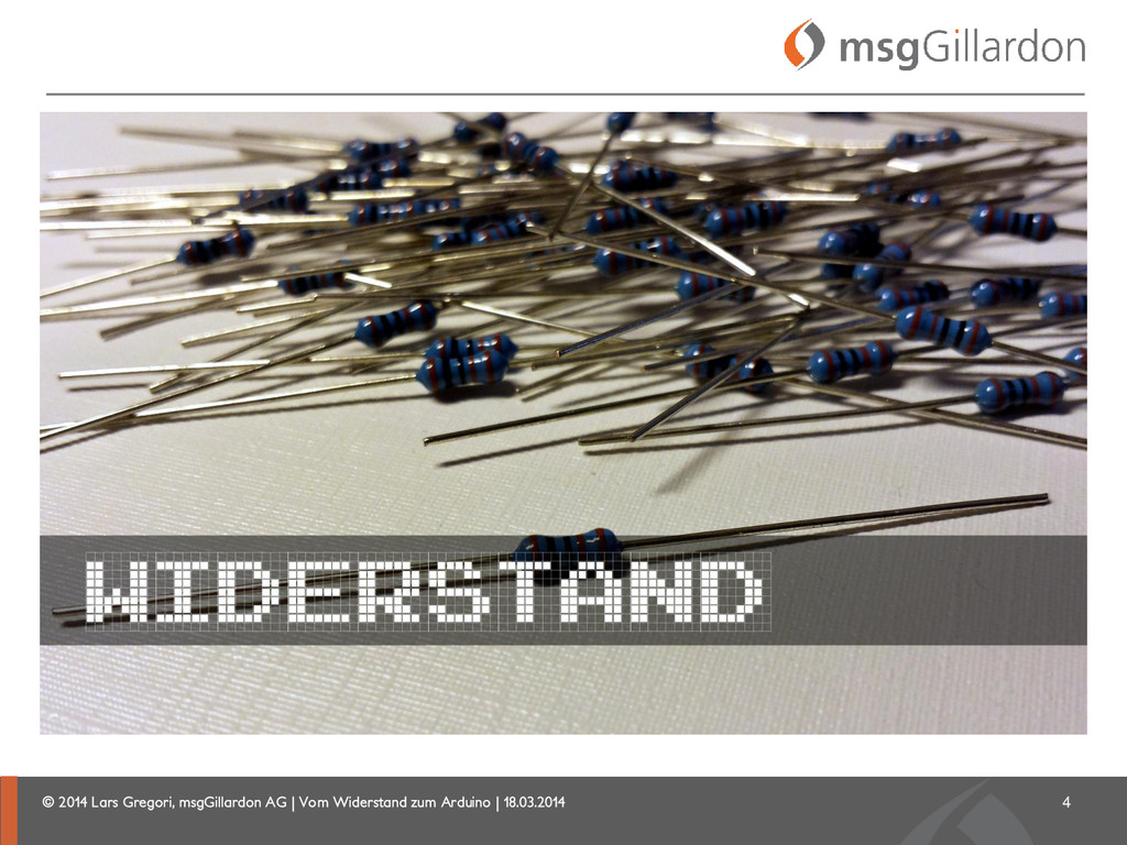
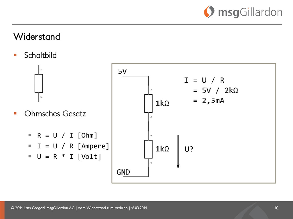
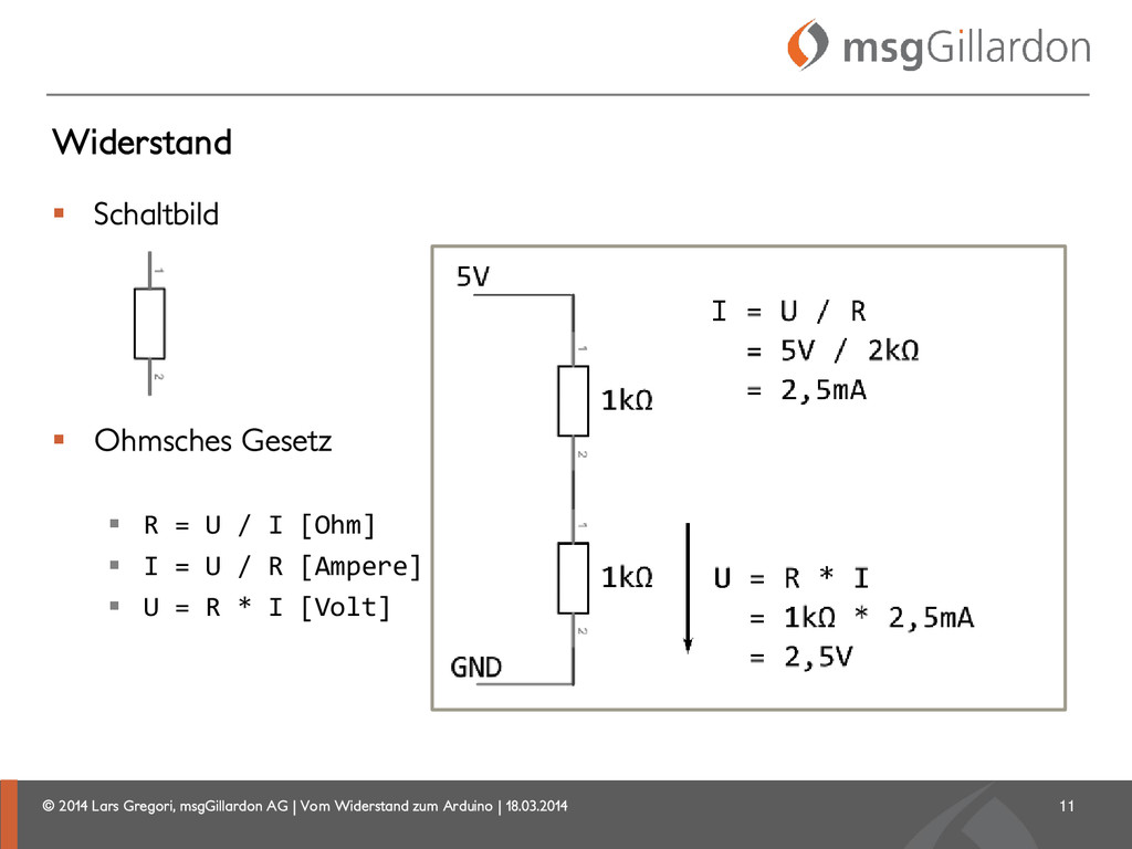
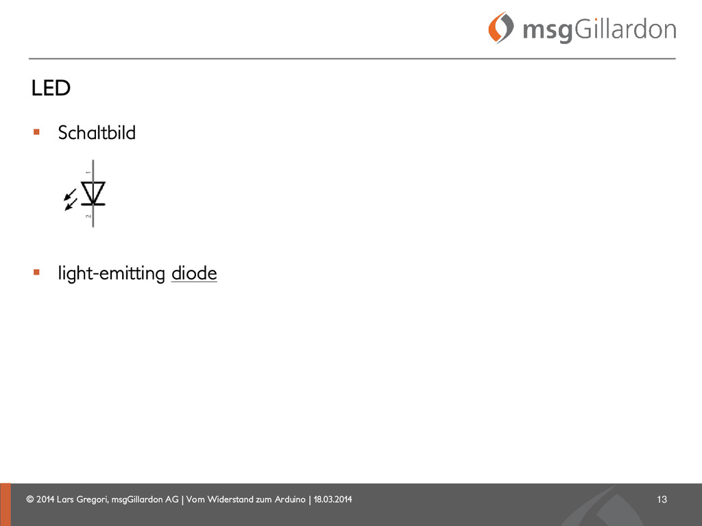
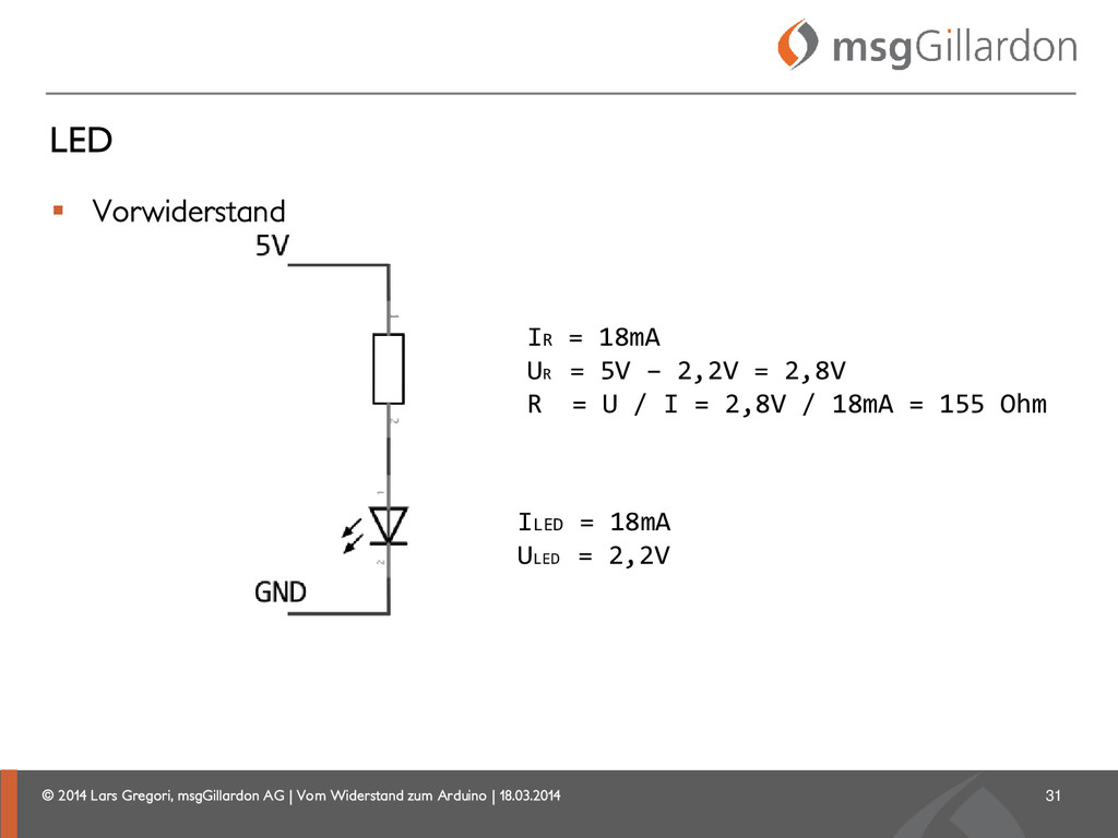
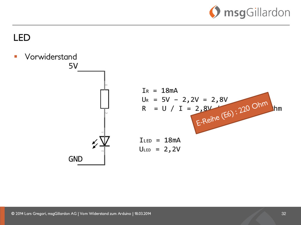
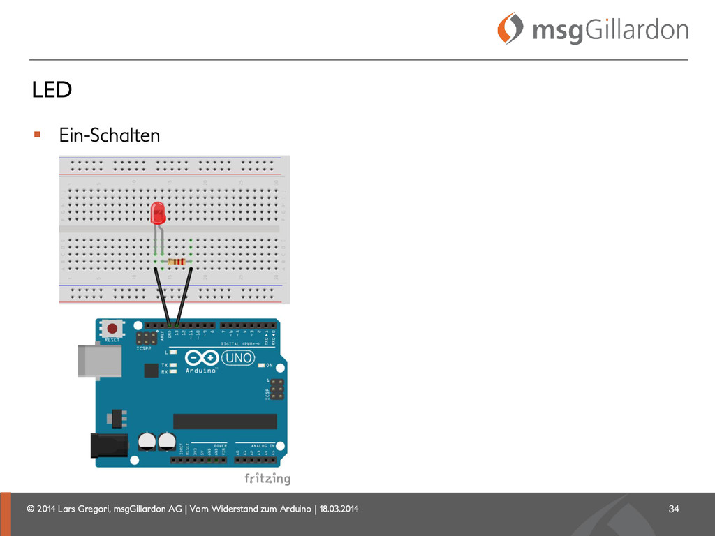
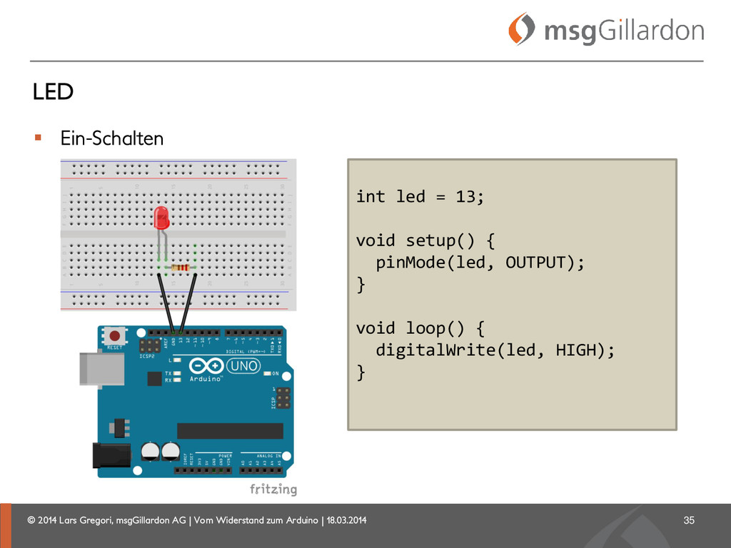
IOT beginnt mit Elektronik. Wer mit IOT anfangen möchte, muss sich auch mit Elektronik auseinandersetzen. Für die meisten eine komplett neue Welt, aber Arduino & Co machen den Einstieg einfach. Dioden, Widerstände, Kondensatoren, Sensoren, etc. sollte man mal gehört haben. Man muss schon etwas Zeit investieren, aber die Hemmschwelle ist dank Arduino & Co stark gesunken.

Lars Gregori

March 18, 2014
Tweet

More Decks by Lars Gregori

Other Decks in Science

Transcript

  1. © 2014 Lars Gregori, msgGillardon AG | Vom Widerstand zum

    Arduino | 18.03.2014 Lars Gregori  Kommunikationselektroniker (Funktechnik)  Informatik Fachrichtung Wirtschaft (FH)  Softwareentwickler (Java Enterprise)  Arduino 2
  2. © 2014 Lars Gregori, msgGillardon AG | Vom Widerstand zum

    Arduino | 18.03.2014 Widerstand  Schaltbild 5
  3. © 2014 Lars Gregori, msgGillardon AG | Vom Widerstand zum

    Arduino | 18.03.2014 Widerstand  Schaltbild  Ohmsches Gesetz  R = U / I [Ohm]  I = U / R [Ampere]  U = R * I [Volt] 6
  4. © 2014 Lars Gregori, msgGillardon AG | Vom Widerstand zum

    Arduino | 18.03.2014 Widerstand  Schaltbild  Ohmsches Gesetz  R = U / I [Ohm]  I = U / R [Ampere]  U = R * I [Volt] 7
  5. © 2014 Lars Gregori, msgGillardon AG | Vom Widerstand zum

    Arduino | 18.03.2014 Widerstand  Schaltbild  Ohmsches Gesetz  R = U / I [Ohm]  I = U / R [Ampere]  U = R * I [Volt] 8
  6. © 2014 Lars Gregori, msgGillardon AG | Vom Widerstand zum

    Arduino | 18.03.2014 Widerstand  Schaltbild  Ohmsches Gesetz  R = U / I [Ohm]  I = U / R [Ampere]  U = R * I [Volt] 9
  7. © 2014 Lars Gregori, msgGillardon AG | Vom Widerstand zum

    Arduino | 18.03.2014 Widerstand  Schaltbild  Ohmsches Gesetz  R = U / I [Ohm]  I = U / R [Ampere]  U = R * I [Volt] 10
  8. © 2014 Lars Gregori, msgGillardon AG | Vom Widerstand zum

    Arduino | 18.03.2014 Widerstand  Schaltbild  Ohmsches Gesetz  R = U / I [Ohm]  I = U / R [Ampere]  U = R * I [Volt] 11
  9. © 2014 Lars Gregori, msgGillardon AG | Vom Widerstand zum

    Arduino | 18.03.2014  Schaltbild  light-emitting diode LED 13
  10. © 2014 Lars Gregori, msgGillardon AG | Vom Widerstand zum

    Arduino | 18.03.2014 Diode  Schaltbild 15
  11. © 2014 Lars Gregori, msgGillardon AG | Vom Widerstand zum

    Arduino | 18.03.2014 Diode  Schaltbild  Sinus von +5V bis -5V 16 ohne Diode
  12. © 2014 Lars Gregori, msgGillardon AG | Vom Widerstand zum

    Arduino | 18.03.2014  Schaltbild  Sinus von +5V bis -5V Diode 17 mit Diode
  13. © 2014 Lars Gregori, msgGillardon AG | Vom Widerstand zum

    Arduino | 18.03.2014 LED  Polung Kathode (Minus)? 19
  14. © 2014 Lars Gregori, msgGillardon AG | Vom Widerstand zum

    Arduino | 18.03.2014 LED  Polung Kathode (Minus)  flache Seite 20
  15. © 2014 Lars Gregori, msgGillardon AG | Vom Widerstand zum

    Arduino | 18.03.2014 LED  Polung Kathode (Minus)  kurzes Bein 21
  16. © 2014 Lars Gregori, msgGillardon AG | Vom Widerstand zum

    Arduino | 18.03.2014 LED  Polung 22 falsch
  17. © 2014 Lars Gregori, msgGillardon AG | Vom Widerstand zum

    Arduino | 18.03.2014  Polung LED 23 richtig
  18. © 2014 Lars Gregori, msgGillardon AG | Vom Widerstand zum

    Arduino | 18.03.2014  Polung LED 24 richtig ?
  19. © 2014 Lars Gregori, msgGillardon AG | Vom Widerstand zum

    Arduino | 18.03.2014  Vorwiderstand LED 25 ?
  20. © 2014 Lars Gregori, msgGillardon AG | Vom Widerstand zum

    Arduino | 18.03.2014  Datenblatt LED 26
  21. © 2014 Lars Gregori, msgGillardon AG | Vom Widerstand zum

    Arduino | 18.03.2014  Datenblatt LED 27
  22. © 2014 Lars Gregori, msgGillardon AG | Vom Widerstand zum

    Arduino | 18.03.2014  Vorwiderstand LED 28 ? ILED = 18mA ULED = 2,2V
  23. © 2014 Lars Gregori, msgGillardon AG | Vom Widerstand zum

    Arduino | 18.03.2014  Vorwiderstand LED 29 ILED = 18mA ULED = 2,2V IR = 18mA UR = R = ?
  24. © 2014 Lars Gregori, msgGillardon AG | Vom Widerstand zum

    Arduino | 18.03.2014  Vorwiderstand LED 30 ILED = 18mA ULED = 2,2V IR = 18mA UR = 5V – 2,2V = 2,8V R =
  25. © 2014 Lars Gregori, msgGillardon AG | Vom Widerstand zum

    Arduino | 18.03.2014  Vorwiderstand LED 31 ILED = 18mA ULED = 2,2V IR = 18mA UR = 5V – 2,2V = 2,8V R = U / I = 2,8V / 18mA = 155 Ohm
  26. © 2014 Lars Gregori, msgGillardon AG | Vom Widerstand zum

    Arduino | 18.03.2014  Vorwiderstand LED 32 ILED = 18mA ULED = 2,2V IR = 18mA UR = 5V – 2,2V = 2,8V R = U / I = 2,8V / 18mA = 155 Ohm
  27. © 2014 Lars Gregori, msgGillardon AG | Vom Widerstand zum

    Arduino | 18.03.2014 LED  Ein-Schalten 34
  28. © 2014 Lars Gregori, msgGillardon AG | Vom Widerstand zum

    Arduino | 18.03.2014 LED  Ein-Schalten 35 int led = 13; void setup() { pinMode(led, OUTPUT); } void loop() { digitalWrite(led, HIGH); }
  29. © 2014 Lars Gregori, msgGillardon AG | Vom Widerstand zum

    Arduino | 18.03.2014 LED  Blinken 36
  30. © 2014 Lars Gregori, msgGillardon AG | Vom Widerstand zum

    Arduino | 18.03.2014 LED  Blinken 37
  31. © 2014 Lars Gregori, msgGillardon AG | Vom Widerstand zum

    Arduino | 18.03.2014 LED  Fade  “analog”  PWM 38 int led = 9; int brightness = 0; int fadeAmount = 5; void setup() { pinMode(led, OUTPUT); } void loop() { analogWrite(led, brightness); brightness = brightness + fadeAmount; if (brightness == 0 || brightness == 255) { fadeAmount = -fadeAmount; } delay(30); }
  32. © 2014 Lars Gregori, msgGillardon AG | Vom Widerstand zum

    Arduino | 18.03.2014 Pulse Width Modulation (PWM)  http://arduino.cc/en/Tutorial/PWM 39
  33. © 2014 Lars Gregori, msgGillardon AG | Vom Widerstand zum

    Arduino | 18.03.2014 Servo Motor  #include <Servo.h>  myservo.attach  myservo.write 41
  34. © 2014 Lars Gregori, msgGillardon AG | Vom Widerstand zum

    Arduino | 18.03.2014 Motor   “Each pin can provide or receive a maximum of 40 mA”  http://arduino.cc/en/Main/arduinoBoardUno 43
  35. © 2014 Lars Gregori, msgGillardon AG | Vom Widerstand zum

    Arduino | 18.03.2014 Transistor  Schaltbild  Verstärker 45
  36. © 2014 Lars Gregori, msgGillardon AG | Vom Widerstand zum

    Arduino | 18.03.2014 Motor  Schutzdiode 49
  37. © 2014 Lars Gregori, msgGillardon AG | Vom Widerstand zum

    Arduino | 18.03.2014 Microcontroller AT mega328 Operating Voltage 5V Input Voltage (recommended) 7-12V Input Voltage (limits) 6-20V Digital I/O Pins 14 (of which 6 provide PWM output) Analog Input Pins 6 DC Current per I/O Pin 40 mA DC Current for 3.3V Pin 50 mA Flash Memory 32 KB (AT mega328) of which 0.5 KB used by bootloader SRAM 2 KB (AT mega328) EEPROM 1 KB (AT mega328) Clock Speed 16 MHz Arduino Uno : http://arduino.cc/en/Main/ArduinoBoardUno 53
  38. © 2014 Lars Gregori, msgGillardon AG | Vom Widerstand zum

    Arduino | 18.03.2014 Language  http://arduino.cc/en/Reference/HomePage  Structure  setup  loop  …  Variables  HIGH, LOW  …  Functions  pinMode  digitalWrite  digitalRead  … 56
  39. © 2014 Lars Gregori, msgGillardon AG | Vom Widerstand zum

    Arduino | 18.03.2014 Standard Libraries  EEPROM  LiquidCrystal - for controlling liquid crystal displays (LCDs)  Servo - for controlling servo motors  … 57
  40. © 2014 Lars Gregori, msgGillardon AG | Vom Widerstand zum

    Arduino | 18.03.2014 LiquidCrystal.h  http://www.arduino.cc/en/Tutorial/LiquidCrystal 59 #include <LiquidCrystal.h> LiquidCrystal lcd(12, 11, 5, 4, 3, 2); void setup() { lcd.begin(16, 2); lcd.print("hello, world!"); }
  41. © 2014 Lars Gregori, msgGillardon AG | Vom Widerstand zum

    Arduino | 18.03.2014 LiquidCrystal.h  http://www.arduino.cc/en/Tutorial/LiquidCrystal 60
  42. © 2014 Lars Gregori, msgGillardon AG | Vom Widerstand zum

    Arduino | 18.03.2014 Nokia 5110 / 3310  http://learn.adafruit.com/nokia-5110-3310-monochrome-lcd 62
  43. © 2014 Lars Gregori, msgGillardon AG | Vom Widerstand zum

    Arduino | 18.03.2014 Sensoren  65
  44. © 2014 Lars Gregori, msgGillardon AG | Vom Widerstand zum

    Arduino | 18.03.2014 Sensoren DIY  Capacitive Sensing Library  http://playground.arduino.cc/Main/CapacitiveSensor?from=Main.CapSense 66
  45. © 2014 Lars Gregori, msgGillardon AG | Vom Widerstand zum

    Arduino | 18.03.2014 Kommunikation Master-Slave-Bus  Two Wire Interface (TWI) bzw. I²C  2 Signalleitungen (SDA und SCL)  Serial Peripheral Interface (SPI)  4 Signalleitungen (SCK, MOSI, MOSO, SS) 68
  46. © 2014 Lars Gregori, msgGillardon AG | Vom Widerstand zum

    Arduino | 18.03.2014 Firmata  Standard Library  for communicating with applications on the computer using a standard serial protocol  http://firmata.org/  Computer ist der Host  Jede Programmiersprache, die den Serial Port unterstützt.  http://firmata.org/wiki/Download 69
  47. © 2014 Lars Gregori, msgGillardon AG | Vom Widerstand zum

    Arduino | 18.03.2014 ATTiny 85  Atmel 8-bit AVR Microcontroller  8 KBytes In-System Programmable Program Memory Flash  512 Bytes In-System Programmable EEPROM  512 Bytes Internal SRAM  2.7V - 5.5V (ATtiny85), 1.8V - 5.5V (ATtiny85V) 75
  48. © 2014 Lars Gregori, msgGillardon AG | Vom Widerstand zum

    Arduino | 18.03.2014 ATTiny 85  6 I/O Pins  2 High Frequency PWM Outputs  4 ADC (10-bit) 76
  49. © 2014 Lars Gregori, msgGillardon AG | Vom Widerstand zum

    Arduino | 18.03.2014 Shields  Standard Libaries  SD  Ethernet  WiFi  GSM  TFT  … 79
  50. © 2014 Lars Gregori, msgGillardon AG | Vom Widerstand zum

    Arduino | 18.03.2014 IOIO Board  pronounced "yo-yo"  https://github.com/ytai/ioio/wiki  Host für Android und PC  USB oder Bluetooth  high-level Java API (Android Apps)  Digital Input/Output, PWM, Analog Input, I2C, SPI und UART 81
  51. © 2014 Lars Gregori, msgGillardon AG | Vom Widerstand zum

    Arduino | 18.03.2014 Raspberry PI  http://www.raspberrypi.org/faqs  700-MHz-ARM11-Prozessor  256 oder 512 MB RAM  Ethernet  2 USB  Linux 83
  52. © 2014 Lars Gregori, msgGillardon AG | Vom Widerstand zum

    Arduino | 18.03.2014 GPIO - General Purpose Input / Output  17 GPIO Pins für Ein- oder Ausgabe  3,3V (level shifter)  SPI, I²C und UART  Programmierung zum Beispiel mit Python  … oder Bash 84 echo "4" > /sys/class/gpio/export echo "in" > /sys/class/gpio/gpio4/direction cat /sys/class/gpio/gpio4/value 0 echo "4" > /sys/class/gpio/unexport
  53. © 2014 Lars Gregori, msgGillardon AG | Vom Widerstand zum

    Arduino | 18.03.2014 Credit  Fonts  Famirids http://www.dafont.com/famirids.font  Petita http://www.dafont.com/petita.font 87