Group 3 Fiber Optic Cables Topics Covered: Introduction to Optical Fiber Classification of FOC based on modes: Single Mode Multi Mode Linearly Polarized Model Fiber Optic Cables | Group 3
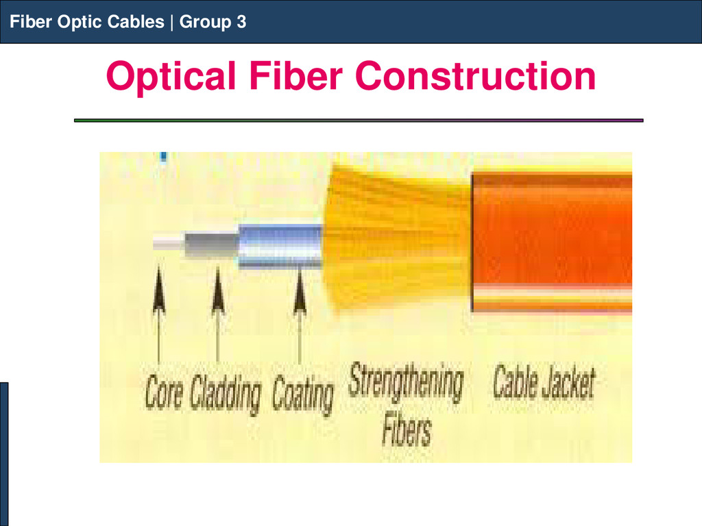
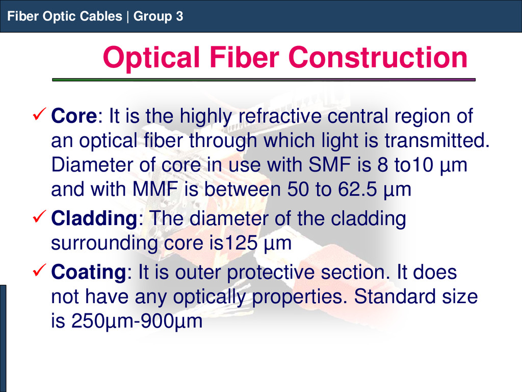
Group 3 Optical Fiber Construction Fiber Optic Cables | Group 3 Core: It is the highly refractive central region of an optical fiber through which light is transmitted. Diameter of core in use with SMF is 8 to10 µm and with MMF is between 50 to 62.5 µm Cladding: The diameter of the cladding surrounding core is125 µm Coating: It is outer protective section. It does not have any optically properties. Standard size is 250µm-900µm
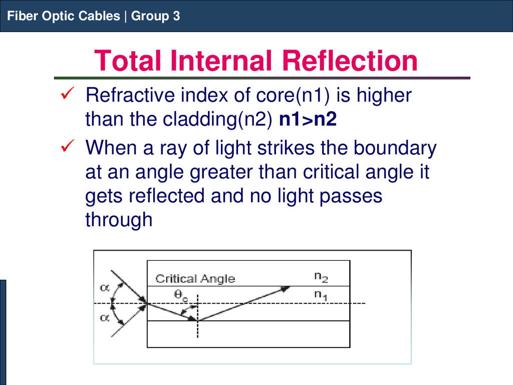
Refractive index of core(n1) is higher than the cladding(n2) n1>n2 When a ray of light strikes the boundary at an angle greater than critical angle it gets reflected and no light passes through Fiber Optic Cables | Group 3
Group 3 Optical Fiber Components Fiber Connector: an optical fiber connector terminates the end of an optical fiber, and enables quicker connection and disconnection Broadband light source (BBS):a light source that emit lights over a large wavelength range Example: ASE source, EELED,SLED Fiber coupler: an optical device that combines or splits power from optical fibers Circulator: a passive three-port device that couple light from Port 1 to 2 and Port 2 to 3 and have high isolation in other directions Fiber Optic Cables | Group 3
Group 3 Optical Fiber Components Cont.. Mode scrambler: an optical device that mixes optical power in fiber to achieve equal power distribution in all modes Index matching fluid: A liquid with refractive index similar to glass that is used to match the materials at the ends of two fibers to reduce loss and back reflection Wavelength division multiplexer: a device that combines and split lights with different wavelengths Fiber Optic Cables | Group 3
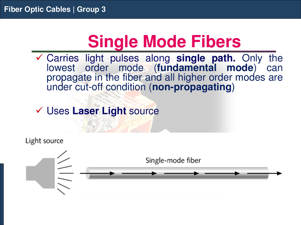
Group 3 Single Mode Fibers Carries light pulses along single path. Only the lowest order mode (fundamental mode) can propagate in the fiber and all higher order modes are under cut-off condition (non-propagating) Uses Laser Light source Fiber Optic Cables | Group 3
Group 3 Single Mode Fibers Fiber Optic Cables | Group 3 Advantages Less dispersion Less degradation Large information capacity Core diameter is about 10 μm Difference between the RI of core and cladding is small Drawbacks Expensive to produce Joining two fibers is difficult Launching of light into single mode is difficult
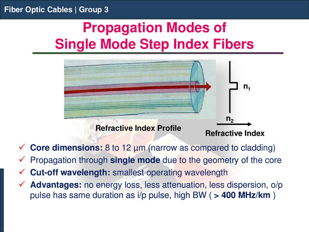
Group 3 Propagation Modes of Single Mode Step Index Fibers Core dimensions: 8 to 12 µm (narrow as compared to cladding) Propagation through single mode due to the geometry of the core Cut-off wavelength: smallest operating wavelength Advantages: no energy loss, less attenuation, less dispersion, o/p pulse has same duration as i/p pulse, high BW ( > 400 MHz/km ) Fiber Optic Cables | Group 3 Refractive Index Refractive Index Profile n1 n2
Group 3 Dispersion Modified Single Mode Fibers During propagation, light ray is subjected to many losses due to: splicing micro-bending losses in connectors losses due to fiber misalignment losses due to NA mismatch Dispersion during propagation causes broadening leading to Inter Symbol Interference that limits Information Carrying Capacity In single mode fibers, intramodal dispersion occurs, caused by material and waveguide dispersion Thus, special Dispersion Modified Single Mode Fibers are used as waveguide dispersion depends upon FOC design Fiber Optic Cables | Group 3
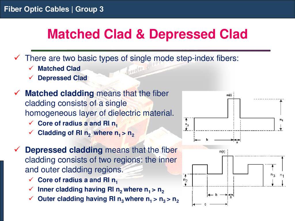
Group 3 Matched Clad & Depressed Clad Fiber Optic Cables | Group 3 There are two basic types of single mode step-index fibers: Matched Clad Depressed Clad Matched cladding means that the fiber cladding consists of a single homogeneous layer of dielectric material. Core of radius a and RI n1 Cladding of RI n2 where n1 > n2 Depressed cladding means that the fiber cladding consists of two regions: the inner and outer cladding regions. Core of radius a and RI n1 Inner cladding having RI n2 where n1 > n2 Outer cladding having RI n3 where n1 > n3 > n2
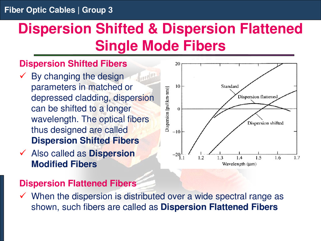
Group 3 Dispersion Shifted & Dispersion Flattened Single Mode Fibers Dispersion Shifted Fibers By changing the design parameters in matched or depressed cladding, dispersion can be shifted to a longer wavelength. The optical fibers thus designed are called Dispersion Shifted Fibers Also called as Dispersion Modified Fibers Fiber Optic Cables | Group 3 Dispersion Flattened Fibers When the dispersion is distributed over a wide spectral range as shown, such fibers are called as Dispersion Flattened Fibers
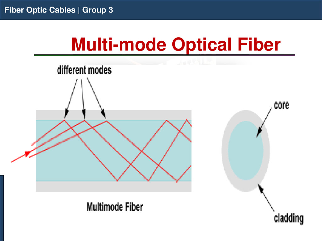
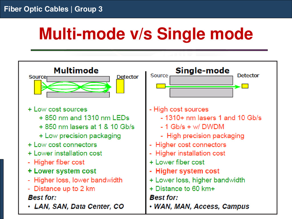
Group 3 Multi-mode Optical Fiber Multi-mode optical fiber is a type of optical fiber mostly used for communication over short distances, such as within a building or on a campus. Typical multimode links have data rates of 10 Mbit/s to 10 Gbit/s over link lengths of up to 600 meters. Fiber Optic Cables | Group 3
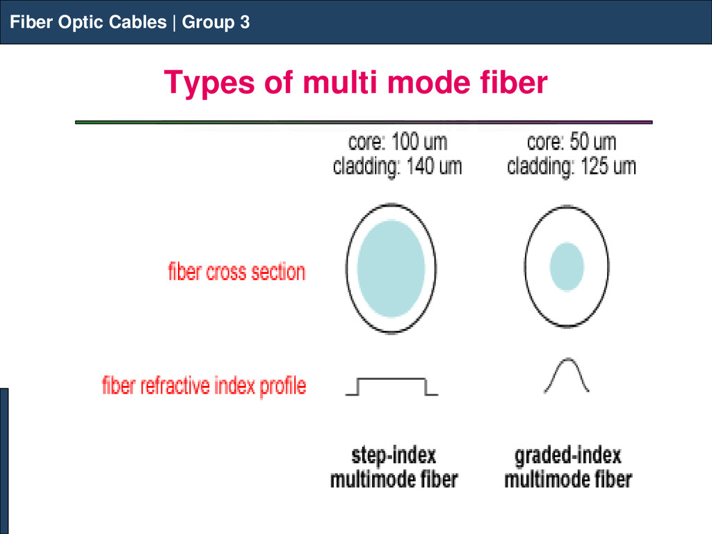
Group 3 About Multi-Mode Fiber Fiber Optic Cables | Group 3 Multi-mode fibers are described by their core and cladding diameters. example: 62.5/125 µm multi-mode fiber. The two types of multi-mode optical fibers are: Step index multi-mode optical fibers Graded index multi-mode optical fibers The transition between the core and cladding can be sharp, which is called a step-index profile, or a gradual transition, which is called a graded-index profile.
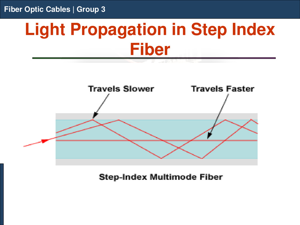
Group 3 Step Index Fiber Step-index multimode fiber has a large core, up to 100 microns in diameter. As a result, some of the light rays that make up the digital pulse may travel a direct route, whereas others zigzag as they bounce off the cladding. These alternative pathways cause the different groupings of light rays, referred to as modes, to arrive separately at the receiver. Fiber Optic Cables | Group 3
Group 3 Step Index Fiber Fiber Optic Cables | Group 3 The pulse begins to spread out, thus losing its well-defined shape. The need to leave spacing between pulses to prevent overlapping limits bandwidth that is, the amount of information that can be sent. Consequently, this type of fiber is best suited for transmission over short distances, in an endoscope, for instance.
Group 3 Modal Dispersion Fiber Optic Cables | Group 3 The arrival of different modes of the light at different times is called Modal Dispersion. Modal dispersion causes pulses to spread out as they travel along the fiber, the more modes the fiber transmits, the more pulses spread out. This significantly limits the bandwidth of step-index multimode fibers. For example, a typical step-index multimode fiber with a 50 µm core would be limited to approximately 20 MHz for a one kilometer length, in other words, a bandwidth of 20 MHz·km.
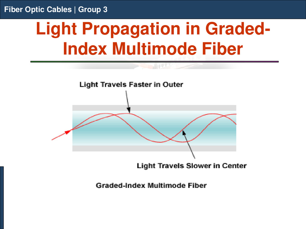
Group 3 Graded-Index Multimode Fibers Fiber Optic Cables | Group 3 Graded-index multimode fibers solves the problem of modal dispersion to a considerable extent. Graded-index multimode fiber contains a core in which the refractive index diminishes gradually from the center axis out toward the cladding. The higher refractive index at the center makes the light rays moving down the axis advance more slowly than those near the cladding.
Group 3 Graded-Index Multimode Fibers Fiber Optic Cables | Group 3 Also, rather than moving in a zigzag fashion off the cladding, light in the core curves helically because of the graded index, reducing its travel distance. The shortened path and the higher speed allow light at the periphery to arrive at a receiver at about the same time as the slow but straight rays in the core axis. The result: a digital pulse suffers less modal dispersion.
Group 3 Advantages of Multi-mode Fiber Fiber Optic Cables | Group 3 easily supports most distances required for premises and enterprise networks can support 10 Gb/s transmission upto 550 meters easier to install and terminate in the field connections can be easily performed in the field, offering installation flexibility and cost savings have larger cores that guide many modes simultaneously.
Group 3 Applications Step-index multimode fibers are mostly used for imaging and illumination. Graded-index multimode fibers are used for data communications and networks carrying signals for typically no more than a couple of kilometers. Fiber Optic Cables | Group 3
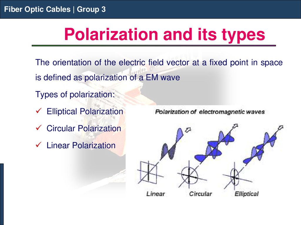
Group 3 Polarization and its types The orientation of the electric field vector at a fixed point in space is defined as polarization of a EM wave Types of polarization: Elliptical Polarization Circular Polarization Linear Polarization Fiber Optic Cables | Group 3
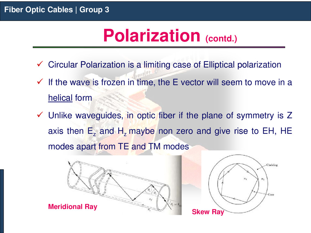
Group 3 Polarization (contd.) Circular Polarization is a limiting case of Elliptical polarization If the wave is frozen in time, the E vector will seem to move in a helical form Unlike waveguides, in optic fiber if the plane of symmetry is Z axis then Ez and Hz maybe non zero and give rise to EH, HE modes apart from TE and TM modes Fiber Optic Cables | Group 3 Meridional Ray Skew Ray
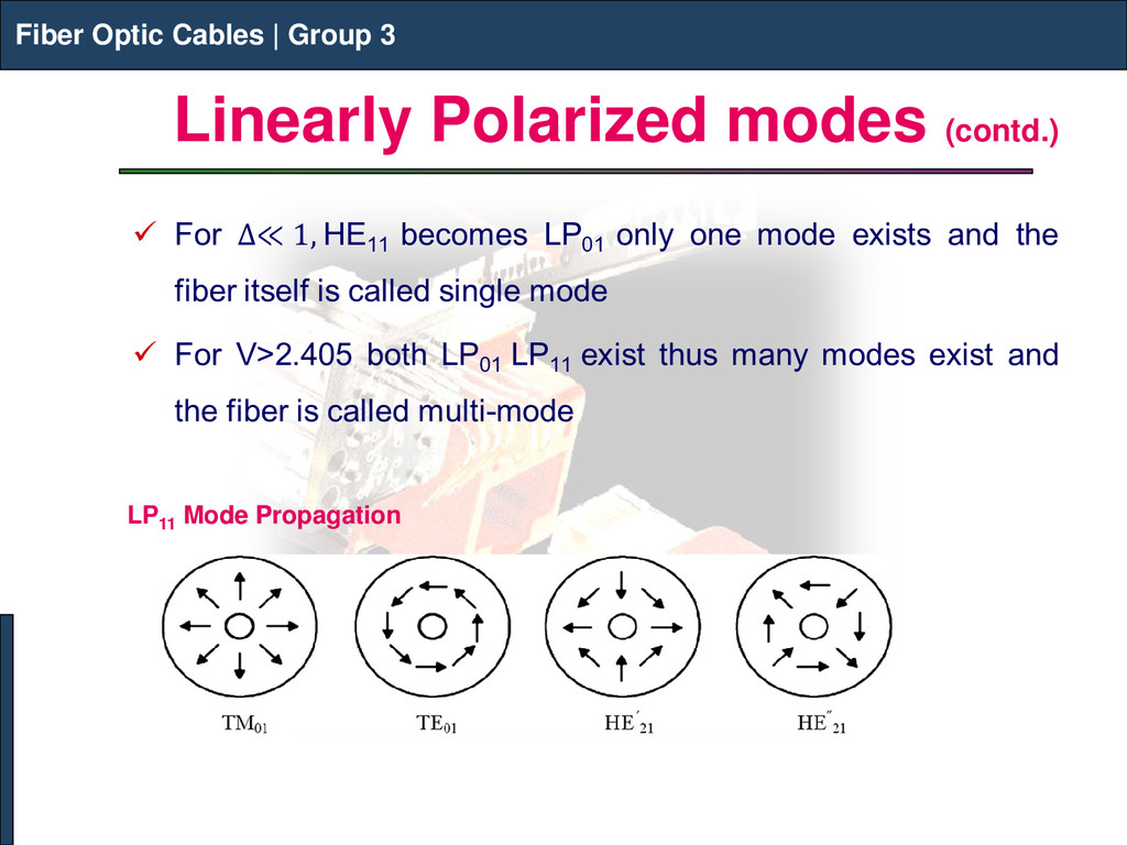
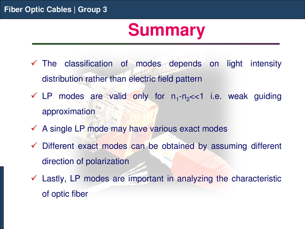
Group 3 Summary The classification of modes depends on light intensity distribution rather than electric field pattern LP modes are valid only for n1 -n2 <<1 i.e. weak guiding approximation A single LP mode may have various exact modes Different exact modes can be obtained by assuming different direction of polarization Lastly, LP modes are important in analyzing the characteristic of optic fiber Fiber Optic Cables | Group 3