Upgrade to Pro — share decks privately, control downloads, hide ads and more …

ESD-MODULE-5_PPT.pdf

Avatar for Rahul Rahul
April 21, 2021
130

 ESD-MODULE-5_PPT.pdf

Avatar for Rahul

Rahul

April 21, 2021
Tweet

Transcript

  1. ECE4003 – EMBEDDED SYSTEM DESIGN 1 Modelling embedded systems Petrinet

    model Modeling examples Unified model language
  2. 2

  3. PETRINET MODEL MODULE - 5  Petri net can also

    called as Place/Transition net  It is used for describing and analyzing concurrent process  Petri net is also a graphical tool  Petri Net(PN) is Very similar to State Transition Diagrams which model the system behavior  It is an abstract model to show the interaction between asynchronous processes  In asynchronous process, start and sequence of processes may vary during the execution ECE4003 – EMBEDDED SYSTEM DESIGN
  4. PETRINET MODEL MODULE - 5 COMPONENTS OF PETRINET MODEL 

    Petri net Model consists of four types of components - places (circles), transitions (rectangles) and arcs (arrows), tokens(black dot):  Places represent possible states of the system;  Transitions are events which cause the change of state  Every arc simply connects a place with a transition or a transition with a place.  Change of state is denoted by a movement of token(s) from place(s) to place(s) ECE4003 – EMBEDDED SYSTEM DESIGN
  5. PETRINET MODEL MODULE - 5  Change of state is

    caused by the firing of a transition  Firing refers to the occurrent of a event  The firing is based on the input conditions, denoted by token availability  A transition is enabled when sufficient tokens are available in input places  Once firing is initiated, tokens will be transferred from input to output places ECE4003 – EMBEDDED SYSTEM DESIGN
  6. PETRINET MODEL MODULE - 5 COMPONENTS OF PETRINET  Below

    is an example Petri net with two places and one transaction. ECE4003 – EMBEDDED SYSTEM DESIGN p2 p1 t1 - p1 : input place - p2 : output place
  7. PETRINET MODEL MODULE - 5  Sequential Execution: Transition t2

    can take place only after t1. Here a constraint is imposed “t2 after t1”  Concurrency: This property is used in modeling distributed control system. t1 and t2 are concurrent process ECE4003 – EMBEDDED SYSTEM DESIGN PROPERTIES
  8. PETRINET MODEL MODULE - 5  Merging: When several tokens

    are arrived at same transition merging will take place  Synchronization: Transition t1 will be enabled only when at least one token is available at each of its input places ECE4003 – EMBEDDED SYSTEM DESIGN PROPERTIES
  9. PETRINET MODEL MODULE - 5 EXAMPLE-1 POINT OF SALE (POS)

    MACHINE  A point of sale terminal (POS terminal) is an electronic device used to process card payments at retail locations. A POS terminal generally does the following:  Reads the information of a customer’s credit or debit card  Validate the user using 4-digit PIN number  Checks whether the funds in a customer’s bank account are sufficient  Transfers the funds from the customer’s account to the seller’s account  Records the transaction and prints a receipt ECE4003 – EMBEDDED SYSTEM DESIGN
  10. PETRINET MODEL MODULE - 5 EXAMPLE-1 POINT OF SALE (POS)

    MACHINE ECE4003 – EMBEDDED SYSTEM DESIGN Scenario 1: Normal  Enters all 4 digits and press OK. Scenario 2: Exceptional  Enters only 3 digits and press OK.
  11. PETRINET MODEL MODULE - 5 EXAMPLE-2 VENDING MACHINE  The

    machine dispenses two kinds of snack bars 20c and 15c. Constraint: 10c and 5c coins can only be used  Scenario 1:  Deposit four 5c, take 20c snack bar.  Scenario 2:  Deposit 10 + 5c, take 15c snack bar.  Scenario 3:  Deposit 5 + 10 + 5c, take 20c snack bar. ECE4003 – EMBEDDED SYSTEM DESIGN
  12. PETRINET MODEL MODULE - 5 EXAMPLE-3 ORDER MANAGEMENT IN A

    RESTAURANT  In the real world, many events are concurrent in nature. Many applications have global state formed from local state.  Scenario 1:  Waiter takes order from customer 1  Serves customer 1  Takes order from customer 2  Serves customer 2.  Scenario 2:  Waiter takes order from customer 1  Takes order from customer 2  Serves customer 2  Serves customer 1 ECE4003 – EMBEDDED SYSTEM DESIGN
  13. PETRINET MODEL MODULE - 5 EXAMPLE-3 ORDER MANAGEMENT IN A

    RESTAURANT ECE4003 – EMBEDDED SYSTEM DESIGN
  14. 16

  15. UNIFIED MODELING LANGUAGE (UML) MODULE - 5  What is

    modeling Language? A modeling language is a graphical/textual computer language explains design and construction of any model or structure following a set of guidelines.  Importance of modeling : Visualization, reduced complexity, documentation  To effectively model a system, you need a language with which the model can be described and here's where UML comes in. ECE4003 – EMBEDDED SYSTEM DESIGN
  16. UNIFIED MODELING LANGUAGE (UML) MODULE - 5 INTRODUCTION  UML

    - general purpose visual modeling language  It is used to visualize, specify, construct, and document  Using tools codes can be generated with UML diagrams in various languages  It is a pictorial language  It can be used for both modeling the software system and non-software systems  For example, modelling a process flow in automated systems, etc. ECE4003 – EMBEDDED SYSTEM DESIGN
  17. UNIFIED MODELING LANGUAGE (UML) MODULE - 5 INTRODUCTION  UML

    is used in many applications by many people like business users, common people to make the system simple, clear and understandable  It is a simple modelling mechanism to model most of the practical systems  It is a object-oriented analysis based method ECE4003 – EMBEDDED SYSTEM DESIGN
  18. UNIFIED MODELING LANGUAGE (UML) MODULE - 5 INTRODUCTION UML Uses:

     Forecast systems  To estimate the reusability.  Lower costs  Plan and analyze system behavior  Easier maintenance/modification ECE4003 – EMBEDDED SYSTEM DESIGN
  19. UNIFIED MODELING LANGUAGE (UML) MODULE - 5 INTRODUCTION There are

    two types of diagram in UML 1. Structure diagram: explains static structure of a system  Class diagram  Object diagram  Deployment diagram  Package diagram 2. Behavior diagram : used to model dynamic changes  Use case diagram  Interaction diagram  Activity diagram  State diagram ECE4003 – EMBEDDED SYSTEM DESIGN
  20. UNIFIED MODELING LANGUAGE (UML) MODULE - 5  Principles of

    UML modeling ECE4003 – EMBEDDED SYSTEM DESIGN Sequence, state and activity diagram System Requirement System Structure System characteristics Use case diagrams Class diagram Implementation Component diagram
  21. 23

  22. UNIFIED MODELING LANGUAGE (UML) MODULE - 5 USE CASE DIAGRAM

     The use case diagram shows different ways a user can interact with the system  It can be used in scenarios like when system interact with people or any other external systems  It contains “use-cases” and ‘’actors’’  Use case diagram depicts how the actor interacts with use cases  It describes the relationship between functionalities and their controllers ECE4003 – EMBEDDED SYSTEM DESIGN
  23. UNIFIED MODELING LANGUAGE (UML) 9 MODULE - 5 USE CASE

    DIAGRAM ECE4003 – EMBEDDED SYSTEM DESIGN Actors Use Cases System Relationships
  24. UNIFIED MODELING LANGUAGE (UML) MODULE - 5 UML NOTATIONS 

    Notations are very important in any modelling language  Efficient use of notations play a major role in making any model meaningful  Use case diagram: Notations of things and relationships  Extensibility makes UML more powerful and flexible. ECE4003 – EMBEDDED SYSTEM DESIGN
  25. UNIFIED MODELING LANGUAGE (UML) MODULE - 5 USE CASE NOTATIONS

     Use case - high level functionalities of a system.  Use case is represented as an eclipse ECE4003 – EMBEDDED SYSTEM DESIGN
  26. UNIFIED MODELING LANGUAGE (UML) MODULE - 5 USE CASE NOTATIONS

    - ACTOR  An actor - the internal or external entities. ECE4003 – EMBEDDED SYSTEM DESIGN
  27. UNIFIED MODELING LANGUAGE (UML) MODULE - 5 USE CASE NOTATIONS

    - DEPENDENCY  Dependency - relationship between two elements of a system  Dependency - dotted arrow  Arrow head represents - independent element  Other end - dependent element ECE4003 – EMBEDDED SYSTEM DESIGN
  28. UNIFIED MODELING LANGUAGE (UML) MODULE - 5 USE CASE NOTATIONS

    - ASSOCIATION  Association - relationship between two elements  Association describes how the elements are associated.  Association is represented by a dotted line with (without) arrows on both sides  The multiplicity (1, *, etc.) to show how many objects are associated ECE4003 – EMBEDDED SYSTEM DESIGN
  29. UNIFIED MODELING LANGUAGE (UML) MODULE - 5 USE CASE NOTATIONS

    - GENERALIZATION  Generalization - parent-child relationship  Generalization - inheritance relationship of the object-oriented concept  Generalization - arrow with a hollow arrow head ECE4003 – EMBEDDED SYSTEM DESIGN
  30. UNIFIED MODELING LANGUAGE (UML) MODULE - 5 USE CASE NOTATIONS

    - <<include>> and <<extend>>  ‘Extend’ and ‘Include’ – between use cases  Include: invocation of one use case by the other  Extend: extending use case will work exactly like the base use case ECE4003 – EMBEDDED SYSTEM DESIGN
  31. UNIFIED MODELING LANGUAGE (UML) MODULE - 5 ECE4003 – EMBEDDED

    SYSTEM DESIGN Primary actor – Initiates the process Secondary actor – Responds Customer Bank Banking Application Use case – Action Log in Check Balance Transfer fund Make Payment Association Verify Password Error <<Include>> <<Extend>> New customer Old customer Exclude Include Generalization
  32. UNIFIED MODELING LANGUAGE (UML) 24 MODULE - 5 USE CASE

    DIAGRAM EXAMPLE- ATM SYSTEM ECE4003 – EMBEDDED SYSTEM DESIGN
  33. UNIFIED MODELING LANGUAGE (UML) 25 MODULE - 5 USE CASE

    DIAGRAM EXAMPLE WASHING MACHINE LAUNDRY ECE4003 – EMBEDDED SYSTEM DESIGN
  34. UNIFIED MODELING LANGUAGE (UML) 26 MODULE - 5 USE CASE

    DIAGRAM EXAMPLE ELEVATOR SYSTEM ECE4003 – EMBEDDED SYSTEM DESIGN
  35. UNIFIED MODELING LANGUAGE (UML) 26 MODULE - 5 USE CASE

    DIAGRAM EXAMPLE ELEVATOR SYSTEM ECE4003 – EMBEDDED SYSTEM DESIGN
  36. 39

  37. UNIFIED MODELING LANGUAGE (UML) MODULE - 5 CLASS DIAGRAM 

    Class diagram- use to document software architecture  It is used to refine the use case diagram  Set of interrelated classes  It contains methods and attributes for classes  Classes can be "is-a" or "has-a" relationship ECE4003 – EMBEDDED SYSTEM DESIGN
  38. UNIFIED MODELING LANGUAGE (UML) MODULE - 5 CLASS DIAGRAM 

    Class diagram - Static diagram, Structural diagram  Class diagram - attributes and operations of a class  It explains the constraints on the system  It is a collection of classes, interfaces, associations, collaborations and constraints ECE4003 – EMBEDDED SYSTEM DESIGN
  39. UNIFIED MODELING LANGUAGE (UML) MODULE - 5 CLASS DIAGRAM 

    The purpose of the class diagram can be summarized as −  Analysis and design of system  Describe responsibilities of a system  Conceptual modelling  Forward and reverse engineering ECE4003 – EMBEDDED SYSTEM DESIGN
  40. UNIFIED MODELING LANGUAGE (UML) MODULE - 5 UML NOTATIONS -

    CLASS  Classes are used to represent objects  UML class diagram is divided into four parts.  Top section - name the class.  Second - attributes of the class.  Third - operations or methods performed by the class.  Fourth - any additional components. ECE4003 – EMBEDDED SYSTEM DESIGN
  41. UNIFIED MODELING LANGUAGE (UML) MODULE - 5 ECE4003 – EMBEDDED

    SYSTEM DESIGN Class Attributes Methods Relationships
  42. UNIFIED MODELING LANGUAGE (UML) MODULE - 5 ECE4003 – EMBEDDED

    SYSTEM DESIGN Attributes Methods Class Student + name: String #Roll: Int -Section: String + display () -Add () -Edit () # Delete () Visibility + Public - Private # protected ~ Package/default Inheritance Anil Sunil Association Aggregation Student Information-Class Diagram
  43. UNIFIED MODELING LANGUAGE (UML) MODULE - 5 ECE4003 – EMBEDDED

    SYSTEM DESIGN Classroom Tables Projector Composition 1 1…* Multiplicity N 0…* 0…1 1…* m…n
  44. UNIFIED MODELING LANGUAGE (UML) 43 MODULE - 5 CLASS DIAGRAM

    EXAMPLE- ATM SYSTEM ECE4003 – EMBEDDED SYSTEM DESIGN
  45. UNIFIED MODELING LANGUAGE (UML) 45 MODULE - 5 CLASS DIAGRAM

    EXAMPLE ELEVATOR SYSTEM ECE4003 – EMBEDDED SYSTEM DESIGN Simplified Class Diagram Detailed Class Diagram
  46. UNIFIED MODELING LANGUAGE (UML) 46 MODULE - 5 CLASS DIAGRAM

    EXAMPLE WASHING MACHINE ECE4003 – EMBEDDED SYSTEM DESIGN
  47. 50

  48. UNIFIED MODELING LANGUAGE (UML) MODULE - 5 SEQUENCE DIAGRAM 

    Sequence diagram - interactions among the different elements in the model  It describes the dynamic behavior of the system  They explain the interaction between objects and collaborations  It emphasizes on the time sequence of messages and structural organizations of the objects ECE4003 – EMBEDDED SYSTEM DESIGN
  49. UNIFIED MODELING LANGUAGE (UML) MODULE - 5 SEQUENCE DIAGRAM 

    Sequence diagram shows the details of the use cases  It shows the complete flow of information, function and operations of the system  It is used in planning and understanding the functionality of existing and future scenario  Time – vertical direction  Header elements – Horizontal direction ECE4003 – EMBEDDED SYSTEM DESIGN
  50. UNIFIED MODELING LANGUAGE (UML) MODULE - 5 SEQUENCE DIAGRAM 

    Sequence Diagrams are suitable for following scenarios:  Usage scenario – to determine how the system could be used  Method logic – to explore logic of any function, procedure or complex process  Service logic – ideal way to explain high level methods used by clients ECE4003 – EMBEDDED SYSTEM DESIGN
  51. UNIFIED MODELING LANGUAGE (UML) MODULE - 5 ECE4003 – EMBEDDED

    SYSTEM DESIGN Lifeline Notation Actor Activation Bar Synchronous message Return message Comment Alt If it is valid Object Else Alternate frame
  52. UNIFIED MODELING LANGUAGE (UML) MODULE - 5 SEQUENCE DIAGRAM EXAMPLE

    PRODUCT PURCHASE SYSTEM  In this sequence diagram we have four objects  Customer  Product  Stock  Payment  The message starts from the top and flows to the bottom (waterfall manner)  Dashed lines - duration for object  Horizontal rectangles - activation of the object  Messages sent - dark arrow and dark arrow head  Return message - dotted arrow ECE4003 – EMBEDDED SYSTEM DESIGN
  53. UNIFIED MODELING LANGUAGE (UML) MODULE - 5 SEQUENCE DIAGRAM EXAMPLE

    - PRODUCT PURCHASE SYSTEM  Customer object - to the product object  Product object -to the stock object  Stock object - saying yes or No.  Product object sends - customer object.  Customer object -payment object to pay money.  Payment object - receipt to the customer object. ECE4003 – EMBEDDED SYSTEM DESIGN
  54. UNIFIED MODELING LANGUAGE (UML) MODULE - 5 ECE4003 – EMBEDDED

    SYSTEM DESIGN Product Stock Payment Customer Request Product In stock? Yes/No Yes/No Payment Receipt PRODUCT PURCHASE SYSTEM
  55. UNIFIED MODELING LANGUAGE (UML) 58 MODULE - 5 SEQUENCE DIAGRAM

    EXAMPLE ELEVATOR SYSTEM ECE4003 – EMBEDDED SYSTEM DESIGN Sequence Diagram for Serving Elevator Button
  56. UNIFIED MODELING LANGUAGE (UML) 59 MODULE - 5 SEQUENCE DIAGRAM

    EXAMPLE VENDING MACHINE ECE4003 – EMBEDDED SYSTEM DESIGN
  57. 60

  58. UNIFIED MODELING LANGUAGE (UML) MODULE - 5 STATE DIAGRAM 

    State diagram stores the status of object  It shows the condition of system over a finite instance of time  It’s a behavioral diagram  It also referred to as State machines and State-chart Diagrams.  It explains the dynamic behavior of a class  State diagrams an be used to understand the reaction of objects on receiving external stimuli ECE4003 – EMBEDDED SYSTEM DESIGN
  59. UNIFIED MODELING LANGUAGE (UML) MODULE - 5 STATE DIAGRAM 

    Uses of state chart diagram:  We use it to depict event driven objects  We use it for showing use cases in business context  Shows the overall behavior of state machine  We use it to model the dynamic behavior of the system .  Steps to draw a state diagram:  Identify the initial state and the final states.  Identify the possible states in which the object can exist  Label the events which trigger these transitions. ECE4003 – EMBEDDED SYSTEM DESIGN
  60. UNIFIED MODELING LANGUAGE (UML) MODULE - 5 ECE4003 – EMBEDDED

    SYSTEM DESIGN Initial state Transition Symbol State Composite State Self Transition Final state STATE DIAGRAM SYMBOL NOTATIONS
  61. UNIFIED MODELING LANGUAGE (UML) MODULE - 5 ECE4003 – EMBEDDED

    SYSTEM DESIGN Idle Send order request v Special or Normal order v Order confirmation v Dispatch order v Initial state Final state Transition Abnormal exit state ONLINE ORDER MANAGEMENT
  62. UNIFIED MODELING LANGUAGE (UML) 59 MODULE - 5 STATE DIAGRAM

    EXAMPLE ATM MACHINE ECE4003 – EMBEDDED SYSTEM DESIGN
  63. UNIFIED MODELING LANGUAGE (UML) 59 MODULE - 5 STATE DIAGRAM

    EXAMPLE ELEVATOR SYSTEM ECE4003 – EMBEDDED SYSTEM DESIGN Statechart for “Elevator Control System" Statechart for "User" Behavior
  64. 67

  65. UNIFIED MODELING LANGUAGE (UML) MODULE - 5 ACTIVITY DIAGRAM 

    An activity diagram - behavioral diagram  It shows the control flow from start to finish point including other decisions paths that is being executed  It can explain both sequential and concurrent processing ECE4003 – EMBEDDED SYSTEM DESIGN
  66. UNIFIED MODELING LANGUAGE (UML) MODULE - 5 ACTIVITY DIAGRAM 

    Uses of Activity chart diagram:  Modeling work flow by using activities  Modeling the logic of algorithm  Shows the workflow process between users and system  Understanding system's functionalities.  Investigating business requirements at a later stage. ECE4003 – EMBEDDED SYSTEM DESIGN
  67. UNIFIED MODELING LANGUAGE (UML) MODULE - 5 ACTIVITY DIAGRAM 

    Steps to draw a activity diagram:  Identify the initial state and the final states.  Identify the intermediate activities needed to reach the final state from he initial state.  Identify the conditions or constraints which cause the system to change control flow.  Draw the diagram with appropriate notations. ECE4003 – EMBEDDED SYSTEM DESIGN
  68. UNIFIED MODELING LANGUAGE (UML) MODULE - 5 ECE4003 – EMBEDDED

    SYSTEM DESIGN ACTIVITY DIAGRAM SYMBOL NOTATIONS Activity Action Control flow Object flow Initial node Final node Object node Decision node Merge node Fork node Join node
  69. UNIFIED MODELING LANGUAGE (UML) MODULE - 5 Activity Diagram of

    an Order Management System ECE4003 – EMBEDDED SYSTEM DESIGN Customer sends an order request Order request system confirms the order Confirm order Dispatch order Start of process Termination [Yes] [No] Condition check [Yes] [No]
  70. UNIFIED MODELING LANGUAGE (UML) 59 MODULE - 5 ACTIVITY DIAGRAM

    EXAMPLE ELEVATOR SYSTEM ECE4003 – EMBEDDED SYSTEM DESIGN Request Elevator Activity ELC – Elevator Logic Control ERS – Elevator Request Service
  71. UNIFIED MODELING LANGUAGE (UML) 59 MODULE - 5 ACTIVITY DIAGRAM

    EXAMPLE VENDING MACHINE ECE4003 – EMBEDDED SYSTEM DESIGN
  72. 75

  73. MODULE - 5 COMPONENT DIAGRAM  Component diagram is used

    to show the relationship between different components in a system  These diagrams are used to show organization and dependencies among set of components  UML component diagram will help in imagining physical system  Component diagram mainly focus on describing physical artefacts of a system like files, executables, libraries, etc. ECE4003 – EMBEDDED SYSTEM DESIGN UNIFIED MODELING LANGUAGE (UML)
  74. MODULE - 5 COMPONENT DIAGRAM  Once the system is

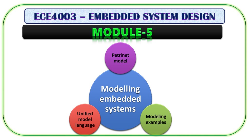
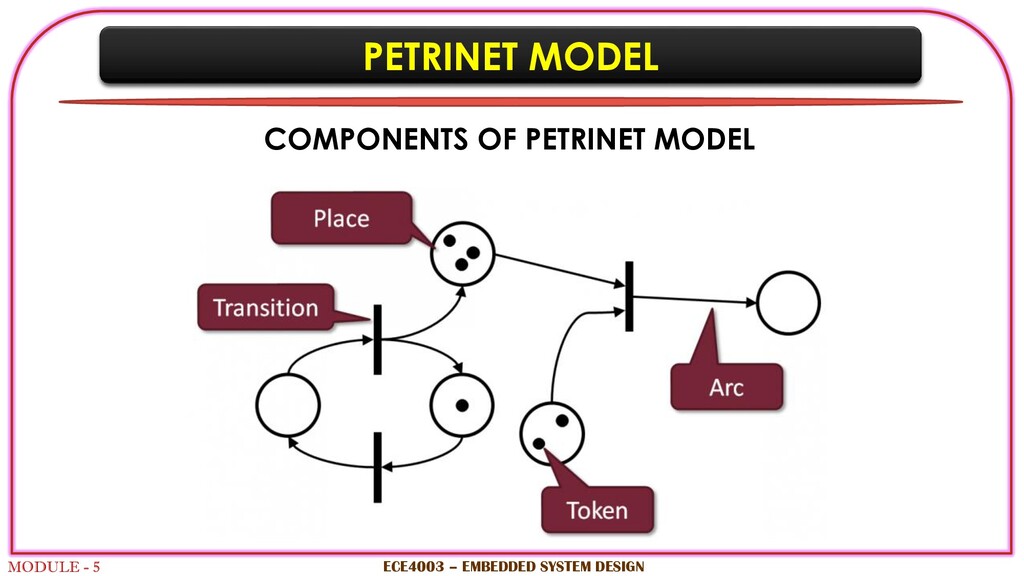
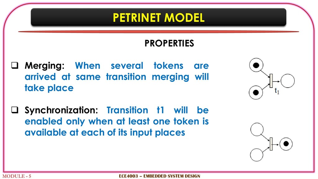
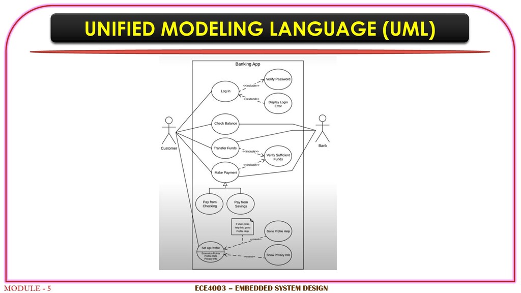
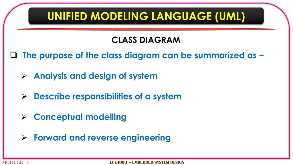
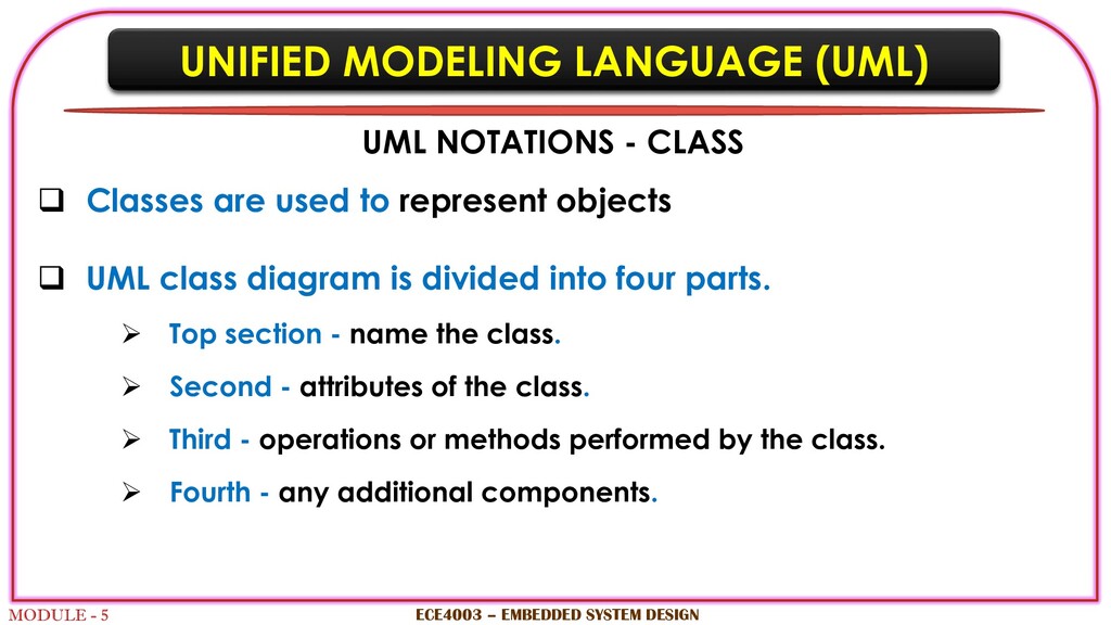
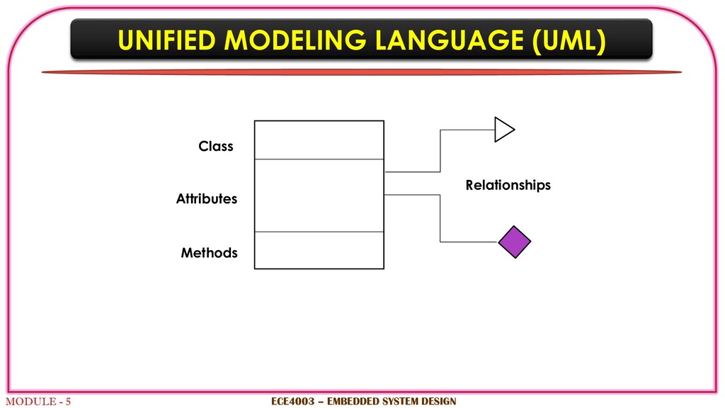
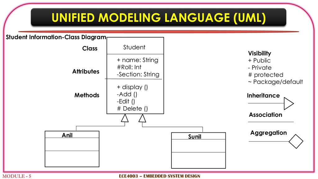
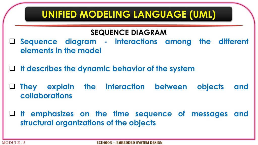
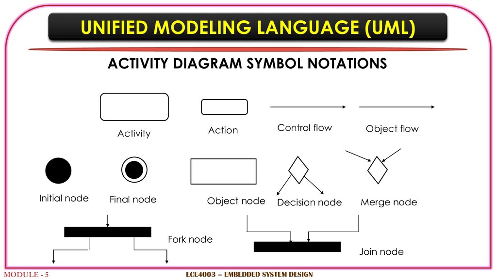
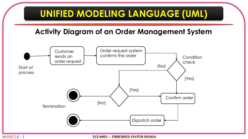
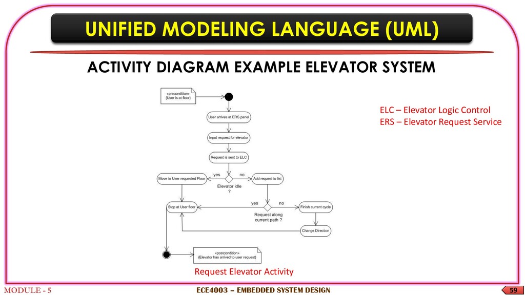
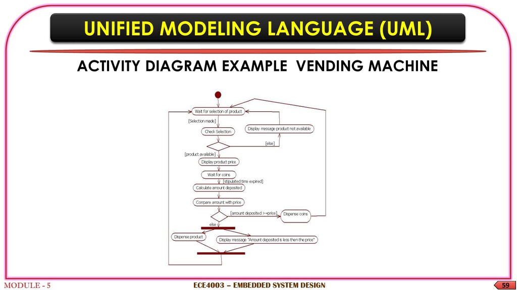
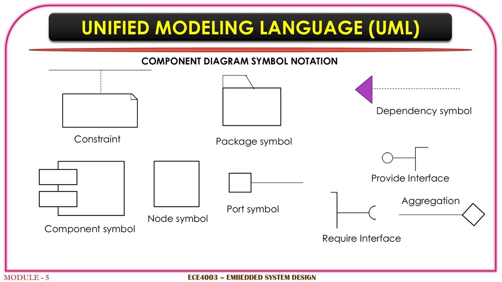
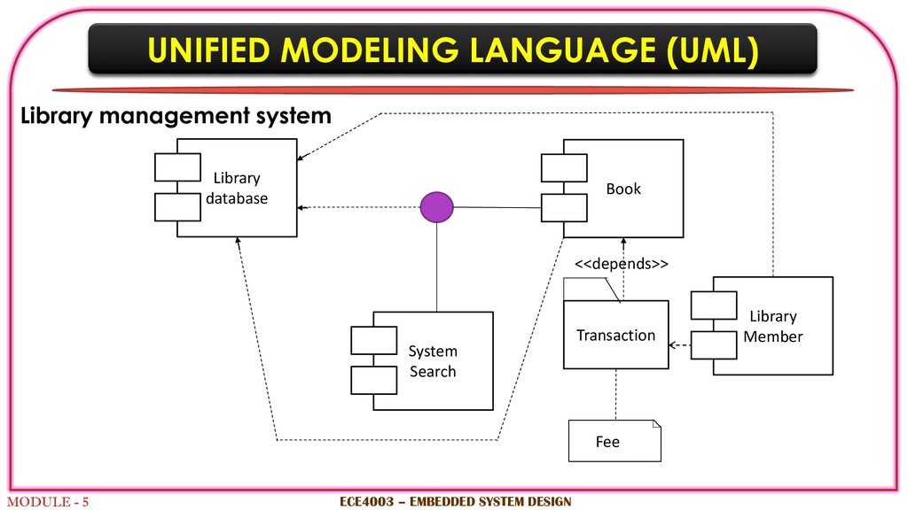
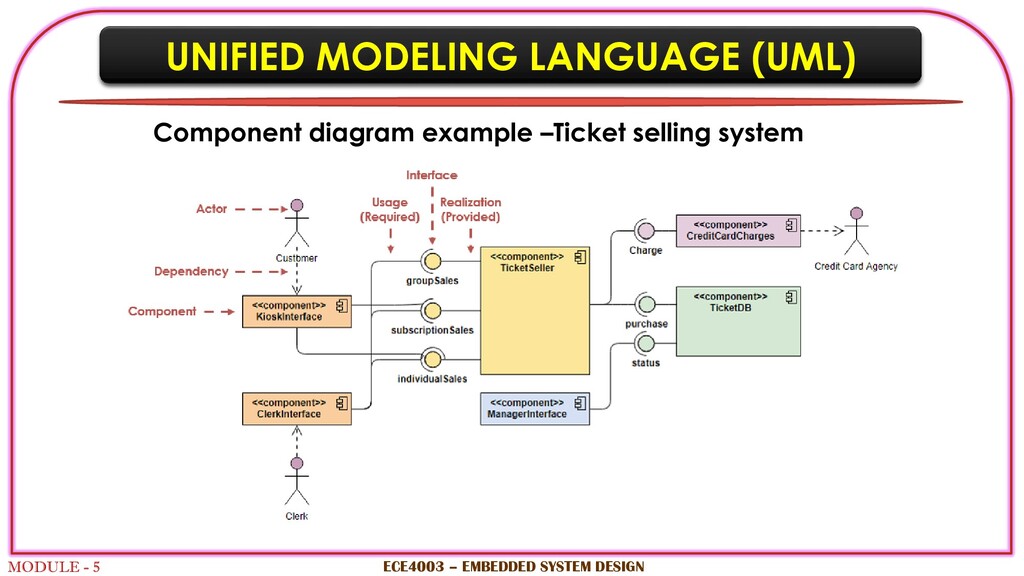
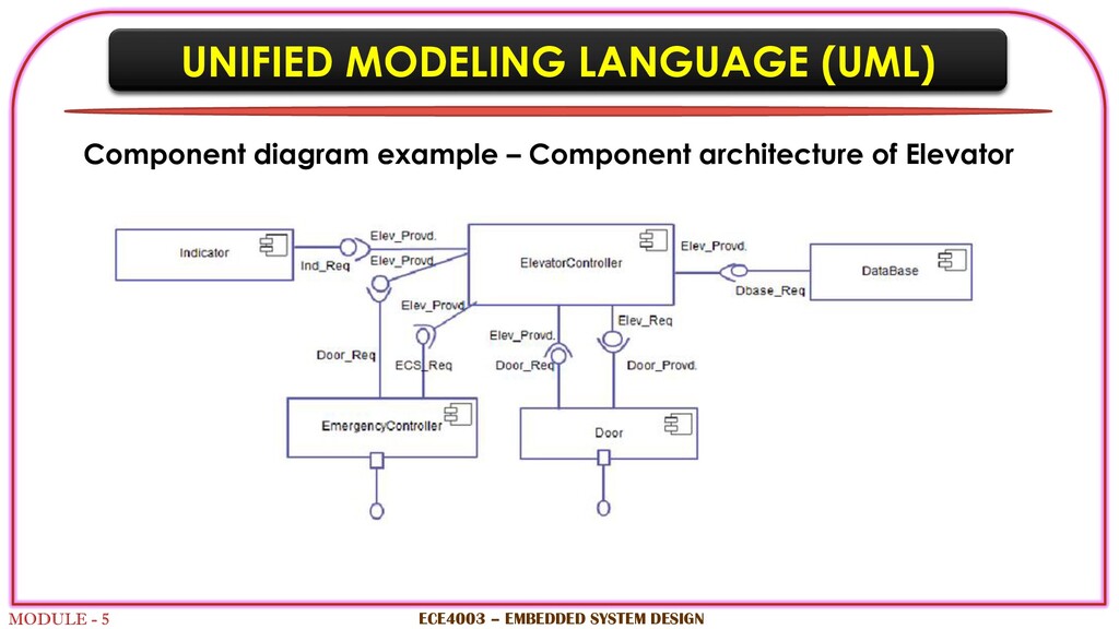
    designed using other UML diagrams and artefacts are ready, component diagram will provide better idea for implementation  Before proceeding with component diagram, files used in the system, libraries and other artefact, relationship among artifacts should be identified  After developing component diagram, meaningful names should be used for better identification of components in the future ECE4003 – EMBEDDED SYSTEM DESIGN UNIFIED MODELING LANGUAGE (UML)
  75. MODULE - 5 COMPONENT DIAGRAM How to draw component diagram?

     Two types of components: executables and code libraries  Component icon- is used to represent software module with a well defined interface  Main program – contains the root of the program  Sub program- collection of subroutines but does not contain class definition  Package – specifies the implementation of a class ECE4003 – EMBEDDED SYSTEM DESIGN UNIFIED MODELING LANGUAGE (UML)
  76. MODULE - 5 ECE4003 – EMBEDDED SYSTEM DESIGN Constraint Dependency

    symbol Component symbol Node symbol Port symbol Provide Interface Require Interface Package symbol UNIFIED MODELING LANGUAGE (UML) COMPONENT DIAGRAM SYMBOL NOTATION Aggregation
  77. MODULE - 5 ECE4003 – EMBEDDED SYSTEM DESIGN Library database

    Book System Search Library Member Transaction Fee Library management system <<depends>> UNIFIED MODELING LANGUAGE (UML)
  78. MODULE - 5 ECE4003 – EMBEDDED SYSTEM DESIGN Component diagram

    example –Ticket selling system UNIFIED MODELING LANGUAGE (UML)
  79. MODULE - 5 ECE4003 – EMBEDDED SYSTEM DESIGN UNIFIED MODELING

    LANGUAGE (UML) Component diagram example – Component architecture of Elevator