Upgrade to Pro — share decks privately, control downloads, hide ads and more …

infosec.pdf

Avatar for Rahul Rahul
April 24, 2021
14

 infosec.pdf

Avatar for Rahul

Rahul

April 24, 2021
Tweet

Transcript

  1. Student Handbook Security Analyst SSC/N0903 381 V Troubleshooting information security

    devices This Unit covers: Lesson Plan 4.1 Troubleshooting the Cisco IOS Firewall Configuration 4.2 Troubleshooting routers
  2. Student Handbook Security Analyst SSC/N0903 382 Outcomes Performance Ensuring Measures

    Work Environment / Lab Requirement PC4. Troubleshoot information security devices as per instructions and guidelines PC6. resolve problems with information security devices, following instructions and guidelines PC10. comply policies, standards, procedures, guidelines and service level agreements (SLAs) when troubleshooting information security devices The learners must demonstrate all PCs on given work tasks PCs/Tablets/Laptops Labs availability (24/7) Internet with WiFi (Min 2 Mbps Dedicated) Networking Equipment- Routers & Switches Firewalls and Access Points Access to all security sites like ISO, PIC DSS Commercial Tools like HP Web Inspect and IBM AppScan etc., Open Source tools like sqlmap, Nessus etc., Security Templates from ITIL You need to know and understand: KA8.standard tools and templates available and how to use these to record troubleshooting KA8. : Presentation of the customized templates by peer groups and validation of them by faculty
  3. Student Handbook Security Analyst SSC/N0903 383 In order to reverse

    (remove) an access list, put a "no" in front of the access-group command in interface configuration mode: int <interface> no ip access-group # in|out If too much traffic is denied, study the logic of your list or try to define an additional broader list, and then apply it instead. For example: access-list # permit tcp any any access-list # permit udp any any access-list # permit icmp any any int <interface> ip access-group # in|out The show ip access-lists command shows which access lists are applied and what traffic is denied by them. If you look at the packet count denied before and after the failed operation with the source and destination IP address, this number increases if the access list blocks traffic. If the router is not heavily loaded, debugging can be done at a packet level on the extended or ip inspect access list. If the router is heavily loaded, traffic is slowed through the router. Use discretion with debugging commands. Temporarily add the no ip route-cache command to the interface: int <interface> no ip route-cache Then, in enable (but not config) mode: term mon debug ip packet # det produces output similar to this: *Mar 1 04:38:28.078: IP: s=10.31.1.161 (Serial0), d=171.68.118.100 (Ethernet0), g=10.31.1.21, len 100, forward Lesson
  4. Student Handbook Security Analyst SSC/N0903 384 *Mar 1 04:38:28.086: IP:

    s=171.68.118.100 (Ethernet0), d=9.9.9.9 (Serial0), g=9.9.9.9, len 100, forward Extended access lists can also be used with the "log" option at the end of the various statements: access-list 101 deny ip host 171.68.118.100 host 10.31.1.161 log access-list 101 permit ip any any You therefore see messages on the screen for permitted and denied traffic: *Mar 1 04:44:19.446: %SEC-6-IPACCESSLOGDP: list 111 permitted icmp 171.68.118.100 -> 10.31.1.161 (0/0), 15 packets *Mar 1 03:27:13.295: %SEC-6-IPACCESSLOGP: list 118 denied tcp 171.68.118.100(0) -> 10.31.1.161(0), 1 packet If the ip inspect list is suspect, the debug ip inspect <type_of_traffic> command produces output such as this output: Feb 14 12:41:17 10.31.1.52 56: 3d05h: CBAC* sis 258488 pak 16D0DC TCP P ack 3195751223 seq 3659219376(2) (10.31.1.5:11109) => (12.34.56.79:23) Feb 14 12:41:17 10.31.1.52 57: 3d05h: CBAC* sis 258488 pak 17CE30 TCP P ack 3659219378 seq 3195751223(12) (10.31.1.5:11109) <= (12.34.56.79:23)
  5. Student Handbook Security Analyst SSC/N0903 385 Cisco Router Basic Troubleshooting

    Checklist Excerpted from the book The Accidental Administrator: Cisco Router Step-by-Step Configuration Guide (Crawley, Don R., Seattle, WA, soundtraining.net, ISBN 978-0983660729) source of trouble: Physical Layer Stuff: Check power issues. Look for power lights, check plugs, and circuit breakers. Check the Interfaces: Use the command show ip interface brief or show ipv6 interface brief to ensure that desired interfaces are up and configured properly. Ping: Use the ping and trace commands to check for connectivity. Check the Routing Table: Use the show ip route or show ipv6 route command to find out what the router knows. Is there either an explicit route to the remote network or a gateway of last resort? Is there a Firewall on the Computer? If the problem involves a computer, check to ensure that its firewall is not blocking packets. Sometimes there are computers at client locations with firewalls in ve the issue, check for access-control lists that block - Is the VPN Up? If a VPN is part of the connection, check to ensure that it is up. Use the show crypto family of commands to check VPN connections. With VPN connections, each end of the connection must mirror the other. For example, even something as seemingly inconsequential as a different timeout value or a different key lifetime can prevent a connection. Do the Protocols Match? If you are trying to gain remote access to a server, ensure that it supports some admins change the default port numbers, so you may expect to use port 22 with SSH, but the admin may have configured it to use a non-standard port. Check for Human Error: User errors can also be the source of errors. Check to ensure that correct usernames and passwords are being used, that you and the admin on the other end of the connection are using the same network addresses and matching subnet masks. Verify Settings: Do not make assumptions. Verify everything! more advanced show and debug commands to isolate the problem.
  6. Student Handbook Security Analyst SSC/N0903 386 Router Troubleshooting Tools Using

    Router Diagnostic Commands Cisco routers provide numerous integrated commands to assist you in monitoring and troubleshooting your internetwork. The following sections describe the basic use of these commands: Using show Commands The show commands are powerful monitoring and troubleshooting tools. You can use the show commands to perform a variety of functions: Monitor router behaviour during initial installation Monitor normal network operation Isolate problem interfaces, nodes, media, or applications Determine when a network is congested Determine the status of servers, clients, or other neighbours Following are some of the most commonly used show commands: show interfaces Use the show interfaces exec command to display statistics for all interfaces configured on the router or access server. The resulting output varies, depending on the network for which an interface has been configured. Some of the more frequently used show interfaces commands include the following: show interfaces ethernet show interfaces tokenring show interfaces fddi show interfaces atm show interfaces serial show controllers This command displays statistics for interface card controllers. For example, the show controllers mci command provides the following fields: The show commands help monitor installation behaviour and normal network behaviour, as well as isolate problem areas. The debug commands assist in the isolation of protocol and configuration problems. The ping commands help determine connectivity between devices on your network. The trace commands provide a method of determining the route by which packets reach their destination from one device to another.
  7. Student Handbook Security Analyst SSC/N0903 387 MCI 0, controller type

    1.1, microcode version 1.8 128 Kbytes of main memory, 4 Kbytes cache memory 22 system TX buffers, largest buffer size 1520 Restarts: 0 line down, 0 hung output, 0 controller error Interface 0 is Ethernet0, station address 0000.0c00.d4a6 15 total RX buffers, 11 buffer TX queue limit, buffer size 1520 Transmitter delay is 0 microseconds Interface 1 is Serial0, electrical interface is V.35 DTE 15 total RX buffers, 11 buffer TX queue limit, buffer size 1520 Transmitter delay is 0 microseconds High speed synchronous serial interface Interface 2 is Ethernet1, station address aa00.0400.3be4 15 total RX buffers, 11 buffer TX queue limit, buffer size 1520 Transmitter delay is 0 microseconds Interface 3 is Serial1, electrical interface is V.35 DCE 15 total RX buffers, 11 buffer TX queue limit, buffer size 1520 Transmitter delay is 0 microseconds High speed synchronous serial interface Some of the most frequently used show controllers commands include the following: show controllers token show controllers FDDI show controllers LEX show controllers ethernet show controllers E1 show controllers MCI show controllers cxbus show controllers t1 show running-config Displays the router configuration currently running show startup-config Displays the router configuration stored in nonvolatile RAM (NVRAM) show flash Group of commands that display the layout and contents of flash memory show buffers Displays statistics for the buffer pools on the router show memory statistics show processes Displays information about the active processes on the router show stacks Displays information about the stack utilization of processes and interrupt routines, as well as the reason for the last system reboot show version Displays the configuration of the system hardware, the software version, the names and sources of configuration files, and the boot images There are hundreds of other show commands available. Using debug Commands The debug privileged exec commands can provide a wealth of information about the traffic being seen (or not seen) on an interface, error messages generated by nodes on the network, protocol-specific diagnostic packets, and other useful troubleshooting data.
  8. Student Handbook Security Analyst SSC/N0903 388 To access and list

    the privileged exec commands, complete the following tasks: Step 1 Enter the privileged exec mode: Command: Router> enable Password: XXXXXX Router# Step 2 List privileged exec commands: Router# debug ? Exercise care when using debug commands. Many debug commands are processor intensive and can cause serious network problems (such as degraded performance or loss of connectivity) if they are enabled on an already heavily loaded router. When you finish using a debug command, remember to disable it with its specific no debug command (or use the no debug all command to turn off all debugging). Use debug commands to isolate problems, not to monitor normal network operation. Because the high processor overhead of debug commands can disrupt router operation, you should use them only when you are looking for specific types of traffic or problems and have narrowed your problems to a likely subset of causes. Output formats vary with each debug command. Some generate a single line of output per packet, and others generate multiple lines of output per packet. Some generate large amounts of output, and others generate only occasional output. Some generate lines of text, and others generate information in field format. To minimize the negative impact of using debug commands, follow this procedure: Step 1 Use the no logging console global configuration command on your router. This command disables all logging to the console terminal. Step 2 Telnet to a router port and enter the enable exec command. The enable exec command will place the router in the privileged exec mode. After entering the enable password, you will receive a prompt that will consist of the router name with a # symbol. Step 3 Use the terminal monitor command to copy debug command output and system error messages to your current terminal display. By redirecting output to your current terminal display, you can view debug command output remotely, without being connected through the console port. If you use debug commands at the console port, character-by-character processor interrupts are generated, maximizing the processor load already caused by using debug. If you intend to keep the output of the debug command, spool the output to a file. Using Router Diagnostic Commands In many situations, using third-party diagnostic tools can be more useful and less intrusive than using debug commands.
  9. Student Handbook Security Analyst SSC/N0903 389 Using the ping Command

    To check host reachability and network connectivity, use the ping exec (user) or privileged exec command. After you log in to the router or access server, you are automatically in user exec command mode. The exec commands available at the user level are a subset of those available at the privileged level. In general, the user exec commands allow you to connect to remote devices, change terminal settings on a temporary basis, perform basic tests, and list system information. The ping command can be used to confirm basic network connectivity on AppleTalk, ISO Connectionless Network Service (CLNS), IP, Novell, Apollo, VINES, DECnet, or XNS networks. For IP, the ping command sends Internet Control Message Protocol (ICMP) Echo messages. ICMP is the Internet protocol that reports errors and provides information relevant to IP packet addressing. If a station receives an ICMP Echo message, it sends an ICMP Echo Reply message back to the source. The extended command mode of the ping command permits you to specify the supported IP header options. This allows the router to perform a more extensive range of test options. To enter ping extended command mode, enter yes at the extended commands prompt of the ping command. It is a good idea to use the ping command when the network is functioning properly to see how the command works under normal conditions and so you have something to compare against when troubleshooting. Using the trace Command The trace user traveling to their destinations. The trace privileged exec command permits the supported IP header options to be specified, allowing the router to perform a more extensive range of test options. The trace command works by using the error message generated by routers when a datagram exceeds its time-to-live (TTL) value. First, probe datagrams are sent with a TTL trace command then sends several probes and displays the round-trip time for each. After every third probe, the TTL is increased by one. error message indicates that an intermediate router has seen and discard discarded it because it could not deliver the packet to an application. If the timer goes off before a response comes in, trace prints an asterisk (*). The trace command terminates when the destination responds, when the maximum TTL is exceeded, or when the user interrupts the trace with the escape sequence. As with ping, it is a good idea to use the trace command when the network is functioning properly to see how the command works under normal conditions and so you have something to compare against when troubleshooting.
  10. Student Handbook Security Analyst SSC/N0903 390 NOTES: __________________________________________________________________________________ __________________________________________________________________________________ __________________________________________________________________________________

    __________________________________________________________________________________ __________________________________________________________________________________ __________________________________________________________________________________ __________________________________________________________________________________ __________________________________________________________________________________ __________________________________________________________________________________ __________________________________________________________________________________ __________________________________________________________________________________ __________________________________________________________________________________ __________________________________________________________________________________ __________________________________________________________________________________ __________________________________________________________________________________ __________________________________________________________________________________ __________________________________________________________________________________ __________________________________________________________________________________ _______________________________________________________________________________ __________________________________________________________________________________
  11. Student Handbook Security Analyst SSC/N0903 391 UN Configuring IDS This

    Unit covers: Lesson Plan 5.1 Cisco IOS Firewall IDS feature 5.2 Cisco IOS Firewall IDS Signature List 5.3 Cisco IOS Firewall IDS Configuration Task List 5.4 Configuring Snort
  12. Student Handbook Security Analyst SSC/N0903 392 Outcomes Performance Ensuring Measures

    Work Environment / Lab Requirement PC1. identify information security devices (IDS) you are required to install/ configure/troubleshoot and source relevant instructions and guidelines PC4. install/configure information security devices (IDS) as per instructions and guidelines PC5. test installed/configured information security devices (IDS), following instructions and guidelines PC6. resolve problems with information security devices (IDS), following instructions and guidelines PC7. obtain advice and guidance on installing / configuring / testing / information security devices (IDS) from appropriate people, where required PC8. record the installation / configuration / testing of information security devices (IDS) promptly using standard templates and tools standards, procedures, guidelines and service level agreements (SLAs) when installing / configuring information security devices (IDS) The learners must demonstrate all PCs on given work tasks KA1 to KA13: PCs/Tablets/Lapt ops Labs availability (24/7) Internet with WiFi (Min 2 Mbps Dedicated) Networking Equipment- Routers & Switches Firewalls and Access Points Access to all security sites like ISO, PIC DSS Commercial Tools like HP Web Inspect and IBM AppScan etc., Open Source tools like sqlmap, Nessus etc., Security Templates from ITIL You need to know and understand: KA1. your organi standards, guidelines and client specific service level agreements for installing, configuring information security devices (IDS) KA2. limits of your role and responsibilities and who to seek guidance from where required KA3. tasks/checklists relevant to your work and how to use these installation guides and procedures and how to access and apply these to install, information security devices (IDS) KA5. who to involve when installing, configuring information security devices (IDS) KA6. methods and techniques used when working with others KA7. the importance of recording issues when KA1-KA3. QA session and a Descriptive write up on understanding. KA4, KA7 Group presentation and peer evaluation along with Faculty. KA5, KA6. Presentation of best practices document by peer group to the faculty and loading the same into different sites KA8. Presentation of the customized templates by peer groups and
  13. Student Handbook Security Analyst SSC/N0903 393 installing/configuring information security devices

    (IDS) and how to report these KA8.standard tools and templates available and how to use these to record installation / configuration KB5. methods of testing installed/configured information security devices (IDS) validation of them by faculty KB5 Installation and configuration of security tools in the lab environment by peer groups and validation by the faculty
  14. Student Handbook Security Analyst SSC/N0903 394 The Cisco IOS Firewall

    IDS feature supports intrusion detection technology for midrange and high- end router platforms with firewall support. It is ideal for any network perimeter, and especially for locations in which a router is being deployed and additional security between network segments is required. It also can protect intranet and extranet connections where additional security is mandated, and branch-office sites connecting to the corporate office or Internet. The Cisco IOS Firewall IDS feature identifies 59 of the most common attacks using "signatures" to detect patterns of misuse in network traffic. The intrusion-detection signatures included in the Cisco IOS Firewall were chosen from a broad cross-section of intrusion-detection signatures. The signatures represent severe breaches of security and the most common network attacks and information-gathering scans. The Cisco IOS Firewall IDS acts as an in-line intrusion detection sensor, watching packets and sessions as they flow through the router, scanning each to match any of the IDS signatures. IDS monitors packets and send alarms when suspicious activity is detected. IDS logs the event through Cisco IOS syslog or the Cisco Secure Intrusion Detection System (Cisco Secure IDS, formerly known as NetRanger) Post Office Protocol. The network administrator can configure the IDS system to choose the appropriate response to various threats. When packets in a session match a signature, the IDS system can be configured to take these actions: Send an alarm to a syslog server or a Cisco Secure IDS Director (centralized management interface) Drop the packet Reset the TCP connection Cisco developed its Cisco IOS software-based intrusion-detection capabilities in Cisco IOS Firewall with flexibility in mind, so that individual signatures could be disabled in case of false positives. Also, while it is preferable to enable both the firewall and intrusion detection features of the CBAC security engine to support a network security policy, each of these features may be enabled independently and on different router interfaces. Cisco IOS software-based intrusion detection is part of the Cisco IOS Firewall. Interaction with Cisco IOS Firewall Default Parameters When Cisco IOS IDS is enabled, Cisco IOS Firewall is automatically enabled. Thus, IDS uses Cisco IOS Firewall default parameter values to inspect incoming sessions. Default parameter values include the following: The rate at which IDS starts deleting half-open sessions (modified via the ip inspect one-minute high command) The rate at which IDS stops deleting half-open sessions (modified via the ip inspect one-minute low command) Lesson
  15. Student Handbook Security Analyst SSC/N0903 395 The maximum incomplete sessions

    (modified via the ip inspect max-incomplete high and the ip inspect max-incomplete low commands) After the incoming TCP session setup rate crosses the one-minute high water mark, the router will reset the oldest half-open session, which is the default behaviour of the Cisco IOS Firewall. Cisco IOS IDS cannot modify this default behaviour. Thus, after a new TCP session rate crosses the one-minute high water mark and a router attempts to open new connections by sending SYN packets at the same time, the latest SYN packet will cause the router to reset the half-open session that was opened by the earlier SYN packet. Only the last SYN request will survive. Compatibility with Cisco Secure Intrusion Detection Cisco IOS Firewall is compatible with the Cisco Secure Intrusion Detection System (formally known as NetRanger). The Cisco Secure IDS is an enterprise-scale, real-time, intrusion detection system designed to detect, report, and terminate unauthorized activity throughout a network. The Cisco Secure IDS consists of three components: Sensor Director Post Office Cisco Secure IDS Sensors, which are high-speed network appliances, analyze the content and context of individual packets to determine if traffic is authorized. If a network's data stream exhibits unauthorized or suspicious activity, such as a SATAN attack, a ping sweep, or the transmission of a secret research project code word, Cisco Secure IDS Sensors can detect the policy violation in real time, forward alarms to a Cisco Secure IDS Director management console, and remove the offender from the network. The Cisco Secure IDS Director is a high-performance, software-based management system that centrally monitors the activity of multiple Cisco Secure IDS Sensors located on local or remote network segments. The Cisco Secure IDS Post Office is the communication backbone that allows Cisco Secure IDS services and hosts to communicate with each other. All communication is supported by a proprietary, connection-based protocol that can switch between alternate routes to maintain point- to-point connections. Cisco Secure IDS customers can deploy the Cisco IOS Firewall IDS signatures to complement their existing IDS systems. This allows an IDS to be deployed to areas that may not be capable of supporting a Cisco Secure IDS Sensor. Cisco IOS Firewall IDS signatures can be deployed alongside or independently of other Cisco IOS Firewall features. The Cisco IOS Firewall IDS can be added to the Cisco Secure IDS Director screen as an icon to provide a consistent view of all intrusion detection sensors throughout a network. The Cisco IOS Firewall intrusion detection capabilities have an enhanced reporting mechanism that permits logging to the Cisco Secure IDS Director console in addition to Cisco IOS syslog. Functional Description The Cisco IOS Firewall IDS acts as an in-line intrusion detection sensor, watching packets as they traverse the router's interfaces and acting upon them in a definable fashion. When a packet, or a number of packets in a session, match a signature, the Cisco IOS Firewall IDS may perform the following configurable actions:
  16. Student Handbook Security Analyst SSC/N0903 396 Alarm Sends an alarm

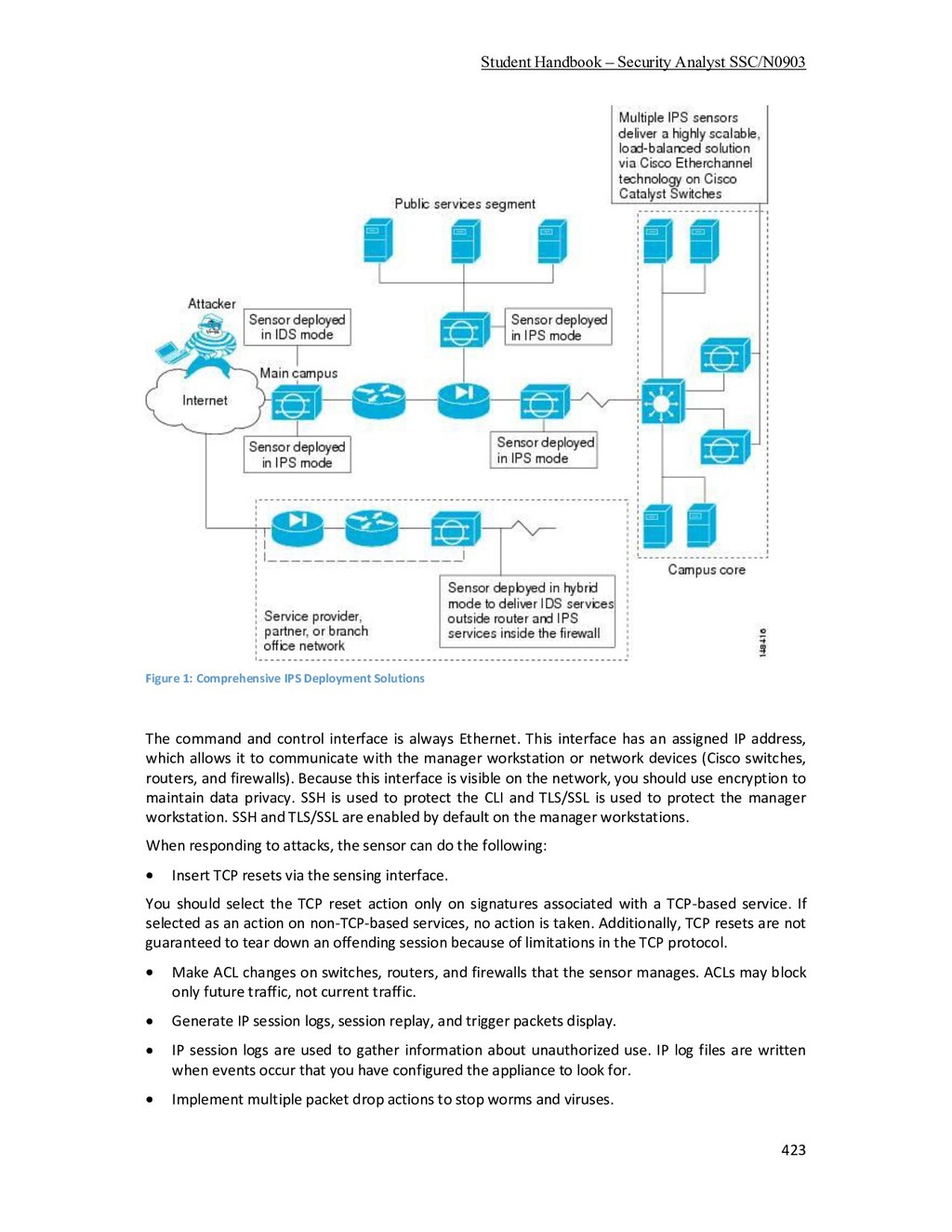
    to a syslog server or Cisco Secure IDS Director Drop Drops the packet Reset Resets the TCP connection The following describes the packet auditing process with Cisco IOS Firewall IDS: You create an audit rule, which specifies the signatures that should be applied to packet traffic and the actions to take when a match is found. An audit rule can apply informational and attack signatures to network packets. The signature list can have just one signature, all signatures, or any number of signatures in between. Signatures can be disabled in case of false positives or the needs of the network environment. You apply the audit rule to an interface on the router, specifying a traffic direction (in or out). If the audit rule is applied to the in direction of the interface, packets passing through the interface are audited before the inbound ACL has a chance to discard them. This allows an administrator to be alerted if an attack or information-gathering activity is underway even if the router would normally reject the activity. If the audit rule is applied to the out direction on the interface, packets are audited after they enter the router through another interface. In this case, the inbound ACL of the other interface may discard packets before they are audited. This may result in the loss of Cisco IOS Firewall IDS alarms even though the attack or information-gathering activity was thwarted. Packets going through the interface that match the audit rule are audited by a series of modules, starting with IP; then either ICMP, TCP, or UDP (as appropriate); and finally, the Application level. If a signature match is found in a module, then the following user-configured action(s) occur: If the action is alarm, then the module completes its audit, sends an alarm, and passes the packet to the next module. If the action is drop, then the packet is dropped from the module, discarded, and not sent to the next module. If the action is reset, then the packets are forwarded to the next module, and packets with the reset flag set are sent to both participants of the session, if the session is TCP. It is recommended that you use the drop and reset actions together. If there are multiple signature matches in a module, only the first match fires an action. Additional matches in other modules fire additional alarms, but only one per module. Note This process is different than on the Cisco Secure IDS Sensor appliance, which identifies all signature matches for each packet. When to Use Firewall IDS Firewall IDS capabilities are ideal for providing additional visibility at intranet, extranet, and branch- office Internet perimeters. Network administrators enjoy more robust protection against attacks on the network and can automatically respond to threats from internal or external hosts. The Firewall with intrusion detection is intended to satisfy the security goals of customers, and is particularly appropriate for the following scenarios: Enterprises that are interested in a cost-effective method of extending their perimeter security across all network boundaries, specifically branch-office, intranet, and extranet perimeters. Small and medium-sized businesses that are looking for a cost-effective router that has an integrated firewall with intrusion-detection capabilities.
  17. Student Handbook Security Analyst SSC/N0903 397 Service providers that want

    to set up managed services, providing firewalling and intrusion detection to their customers, all housed within the necessary function of a router. Memory and Performance Impact The performance impact of intrusion detection will depend on the configuration of the signatures, the level of traffic on the router, the router platform, and other individual features enabled on the router such as encryption, source route bridging, and so on. Enabling or disabling individual signatures will not alter performance significantly, however, signatures that are configured to use Access Control Lists will have a significant performance impact. For auditing atomic signatures, there is no traffic-dependent memory requirement. For auditing compound signatures, CBAC allocates memory to maintain the state of each session for each connection. Memory is also allocated for the configuration database and for internal caching.
  18. Student Handbook Security Analyst SSC/N0903 398 The following is a

    complete list of Cisco IOS Firewall IDS signatures. A signature detects patterns of misuse in network traffic. In Cisco IOS Firewall IDS, signatures are categorized into four types: Info Atomic Info Compound Attack Atomic Attack Compound An info signature detects information-gathering activity, such as a port sweep. An attack signature detects attacks attempted into the protected network, such as denial-of-service attempts or the execution of illegal commands during an FTP session. Info and attack signatures can be either atomic or compound signatures. Atomic signatures can detect patterns as simple as an attempt to access a specific port on a specific host. Compound signatures can detect complex patterns, such as a sequence of operations distributed across multiple hosts over an arbitrary period of time. The intrusion-detection signatures included in the Cisco IOS Firewall were chosen from a broad cross-section of intrusion-detection signatures as representative of the most common network attacks and information-gathering scans that are not commonly found in an operational network. The following signatures are listed in numerical order by their signature number in the Cisco Secure IDS Network Security Database. After each signature's name is an indication of the type of signature (info or attack, atomic or compound). Atomic signatures marked with an asterisk (Atomic*) are allocated memory for session states by CBAC. 1000 IP options-Bad Option List (Info, Atomic) Triggers on receipt of an IP datagram where the list of IP options in the IP datagram header is incomplete or malformed. The IP options list contains one or more options that perform various network management or debugging tasks. 1001 IP options-Record Packet Route (Info, Atomic) Triggers on receipt of an IP datagram where the IP option list for the datagram includes option 7 (Record Packet Route). 1002 IP options-Timestamp (Info, Atomic) Triggers on receipt of an IP datagram where the IP option list for the datagram includes option 4 (Timestamp). 1003 IP options-Provide s,c,h,tcc (Info, Atomic) Triggers on receipt of an IP datagram where the IP option list for the datagram includes option 2 (Security options). 1004 IP options-Loose Source Route (Info, Atomic)
  19. Student Handbook Security Analyst SSC/N0903 399 Triggers on receipt of

    an IP datagram where the IP option list for the datagram includes option 3 (Loose Source Route). 1005 IP options-SATNET ID (Info, Atomic) Triggers on receipt of an IP datagram where the IP option list for the datagram includes option 8 (SATNET stream identifier). 1006 IP options-Strict Source Route (Info, Atomic) Triggers on receipt of an IP datagram in which the IP option list for the datagram includes option 2 (Strict Source Routing). 1100 IP Fragment Attack (Attack, Atomic) Triggers when any IP datagram is received with the "more fragments" flag set to 1 or if there is an offset indicated in the offset field. 1101 Unknown IP Protocol (Attack, Atomic) Triggers when an IP datagram is received with the protocol field set to 101 or greater. These protocol types are undefined or reserved and should not be used. 1102 Impossible IP Packet (Attack, Atomic) This triggers when an IP packet arrives with source equal to destination address. This signature will catch the so-called Land Attack. 2000 ICMP Echo Reply (Info, Atomic) Triggers when a IP datagram is received with the "protocol" field in the IP header set to 1 (ICMP) and the "type" field in the ICMP header set to 0 (Echo Reply). 2001 ICMP Host Unreachable (Info, Atomic) Triggers when an IP datagram is received with the "protocol" field in the IP header set to 1 (ICMP) and the "type" field in the ICMP header set to 3 (Host Unreachable). 2002 ICMP Source Quench (Info, Atomic) Triggers when an IP datagram is received with the "protocol" field in the IP header set to 1 (ICMP) and the "type" field in the ICMP header set to 4 (Source Quench). 2003 ICMP Redirect (Info, Atomic) Triggers when an IP datagram is received with the "protocol" field in the IP header set to 1 (ICMP) and the "type" field in the ICMP header set to 5 (Redirect). 2004 ICMP Echo Request (Info, Atomic) Triggers when an IP datagram is received with the "protocol" field in the IP header set to 1 (ICMP) and the "type" field in the ICMP header set to 8 (Echo Request). 2005 ICMP Time Exceeded for a Datagram (Info, Atomic) Triggers when an IP datagram is received with the "protocol" field in the IP header set to 1 (ICMP) and the "type" field in the ICMP header set to 11(Time Exceeded for a Datagram). 2006 ICMP Parameter Problem on Datagram (Info, Atomic) Triggers when an IP datagram is received with the "protocol" field in the IP header set to 1 (ICMP) and the "type" field in the ICMP header set to 12 (Parameter Problem on Datagram). 2007 ICMP Timestamp Request (Info, Atomic)
  20. Student Handbook Security Analyst SSC/N0903 400 Triggers when an IP

    datagram is received with the "protocol" field in the IP header set to 1 (ICMP) and the "type" field in the ICMP header set to 13 (Timestamp Request). 2008 ICMP Timestamp Reply (Info, Atomic) Triggers when an IP datagram is received with the "protocol" field in the IP header set to 1 (ICMP) and the "type" field in the ICMP header set to 14 (Timestamp Reply). 2009 ICMP Information Request (Info, Atomic) Triggers when an IP datagram is received with the "protocol" field in the IP header set to 1 (ICMP) and the "type" field in the ICMP header set to 15 (Information Request). 2010 ICMP Information Reply (Info, Atomic) Triggers when an IP datagram is received with the "protocol" field in the IP header set to 1 (ICMP) and the "type" field in the ICMP header set to 16 (ICMP Information Reply). 2011 ICMP Address Mask Request (Info, Atomic) Triggers when an IP datagram is received with the "protocol" field in the IP header set to 1 (ICMP) and the "type" field in the ICMP header set to 17 (Address Mask Request). 2012 ICMP Address Mask Reply (Info, Atomic) Triggers when an IP datagram is received with the "protocol" field in the IP header set to 1 (ICMP) and the "type" field in the ICMP header set to 18 (Address Mask Reply). 2150 Fragmented ICMP Traffic (Attack, Atomic) Triggers when an IP datagram is received with the protocol field in the IP header set to 1 (ICMP) and either the more fragments flag is set to 1 (ICMP) or there is an offset indicated in the offset field. 2151 Large ICMP Traffic (Attack, Atomic) Triggers when an IP datagram is received with the protocol field in the IP header set to 1 (ICMP) and the IP length is greater than 1024. 2154 Ping of Death Attack (Attack, Atomic) Triggers when an IP datagram is received with the protocol field in the IP header set to 1 (ICMP), the Last Fragment bit is set, and ( IP offset * 8 ) + (IP data length) > 65535 In other words, the IP offset (which represents the starting position of this fragment in the original packet, and which is in 8-byte units) plus the rest of the packet is greater than the maximum size for an IP packet. 3040 TCP - no bits set in flags (Attack, Atomic) Triggers when a TCP packet is received with no bits set in the flags field. 3041 TCP - SYN and FIN bits set (Attack, Atomic) Triggers when a TCP packet is received with both the SYN and FIN bits set in the flag field. 3042 TCP - FIN bit with no ACK bit in flags (Attack, Atomic) Triggers when a TCP packet is received with the FIN bit set but with no ACK bit set in the flags field. 3050 Half-open SYN Attack/SYN Flood (Attack, Compound)
  21. Student Handbook Security Analyst SSC/N0903 401 Triggers when multiple TCP

    sessions have been improperly initiated on any of several well- known service ports. Detection of this signature is currently limited to FTP, Telnet, HTTP, and e- mail servers (TCP ports 21, 23, 80, and 25 respectively). 3100 Smail Attack (Attack, Compound) Triggers on the very common "smail" attack against SMTP-compliant e-mail servers (frequently sendmail). 3101 Sendmail Invalid Recipient (Attack, Compound) Triggers on any mail message with a "pipe" (|) symbol in the recipient field. 3102 Sendmail Invalid Sender (Attack, Compound) Triggers on any mail message with a "pipe" (|) symbol in the "From:" field. 3103 Sendmail Reconnaissance (Attack, Compound) Triggers when "expn" or "vrfy" commands are issued to the SMTP port. 3104 Archaic Sendmail Attacks (Attack, Compound) Triggers when "wiz" or "debug" commands are issued to the SMTP port. 3105 Sendmail Decode Alias (Attack, Compound) Triggers on any mail message with ": decode@" in the header. 3106 Mail Spam (Attack, Compound) Counts number of Rcpt to: lines in a single mail message and alarms after a user-definable maximum has been exceeded (default is 250). 3107 Majordomo Execute Attack (Attack, Compound) A bug in the Majordomo program will allow remote users to execute arbitrary commands at the privilege level of the server. 3150 FTP Remote Command Execution (Attack, Compound) Triggers when someone tries to execute the FTP SITE command. 3151 FTP SYST Command Attempt (Info, Compound) Triggers when someone tries to execute the FTP SYST command. 3152 FTP CWD ~root (Attack, Compound) Triggers when someone tries to execute the CWD ~root command. 3153 FTP Improper Address Specified (Attack, Atomic*) Triggers if a port command is issued with an address that is not the same as the requesting host. 3154 FTP Improper Port Specified (Attack, Atomic*) Triggers if a port command is issued with a data port specified that is less than 1024 or greater than 65535. 4050 UDP Bomb (Attack, Atomic) Triggers when the UDP length specified is less than the IP length specified. 4100 Tftp Passwd File (Attack, Compound) Triggers on an attempt to access the passwd file (typically /etc/passwd) via TFTP.
  22. Student Handbook Security Analyst SSC/N0903 402 6100 RPC Port Registration

    (Info, Atomic*) Triggers when attempts are made to register new RPC services on a target host. 6101 RPC Port Unregistration (Info, Atomic*) Triggers when attempts are made to unregister existing RPC services on a target host. 6102 RPC Dump (Info, Atomic*) Triggers when an RPC dump request is issued to a target host. 6103 Proxied RPC Request (Attack, Atomic*) Triggers when a proxied RPC request is sent to the portmapper of a target host. 6150 ypserv Portmap Request (Info, Atomic*) Triggers when a request is made to the portmapper for the YP server daemon (ypserv) port. 6151 ypbind Portmap Request (Info, Atomic*) Triggers when a request is made to the portmapper for the YP bind daemon (ypbind) port. 6152 yppasswdd Portmap Request (Info, Atomic*) Triggers when a request is made to the portmapper for the YP password daemon (yppasswdd) port. 6153 ypupdated Portmap Request (Info, Atomic*) Triggers when a request is made to the portmapper for the YP update daemon (ypupdated) port. 6154 ypxfrd Portmap Request (Info, Atomic*) Triggers when a request is made to the portmapper for the YP transfer daemon (ypxfrd) port. 6155 mountd Portmap Request (Info, Atomic*) Triggers when a request is made to the portmapper for the mount daemon (mountd) port. 6175 rexd Portmap Request (Info, Atomic*) Triggers when a request is made to the portmapper for the remote execution daemon (rexd) port. 6180 rexd Attempt (Info, Atomic*) Triggers when a call to the rexd program is made. The remote execution daemon is the server responsible for remote program execution. This may be indicative of an attempt to gain unauthorized access to system resources. 6190 statd Buffer Overflow (Attack, Atomic*) Triggers when a large statd request is sent. This could be an attempt to overflow a buffer and gain access to system resources. 8000 FTP Retrieve Password File (Attack, Atomic*) SubSig ID: 2101 Triggers on string "passwd" issued during an FTP session. May indicate someone attempting to retrieve the password file from a machine in order to crack it and gain unauthorized access to system resources.
  23. Student Handbook Security Analyst SSC/N0903 403 See the following sections

    for configuration tasks for the Cisco IOS Firewall Intrusion Detection System feature. Each task in the list is identified as optional or required: Initializing Cisco IOS Firewall IDS (Required) Initializing the Post Office (Required) Configuring and Applying Audit Rules (Required) Verifying the Configuration (Optional) Initializing Cisco IOS Firewall IDS To initialize Cisco IOS Firewall IDS on a router, use the following commands in global configuration mode: Initializing the Post Office You must reload the router every time you make a Post Office configuration change. To initialize the Post Office system, use the following commands in global configuration mode: Command Purpose Step 1 Router(config)# ip audit notifynr-director or Router(config)#ip audit notifylog Sends event notifications (alarms) to either a Cisco Secure IDS Director, a syslog server, or both. For example, if you are sending alarms to a Cisco Secure IDS Director, use the nr-director keyword in the command syntax. If you are sending alarms to a syslog server, use the log keyword in the command syntax. Step 2 router(config)# ip audit po local hostid host-id orgid org-id Sets the Post Office parameters for both the router (using the ip audit po local command) and the Cisco Secure IDS Director (using the ip audit po remote command). Here, host-id is a unique number between 1 and 65535 that identifies the router, and org-id is a unique number Command Purpose Step 1 Router(config)# ip audit smtp spamrecipients Sets the threshold beyond which spamming in e-mail messages is suspected. Here, recipients is the maximum number of recipients in an e-mail message. The default is 250. Step 2 Router(config)# ip audit po max- eventsnumber_events Sets the threshold beyond which queued events are dropped from the queue for sending to the Cisco Secure IDS Director. Here, eventsnumber events is the number of events in the event queue. The default is 100. Increasing this number may have an impact on memory and performance, as each event in the event queue requires 32 KB of memory. Step 3 Router(config)# exit Exits global configuration mode.
  24. Student Handbook Security Analyst SSC/N0903 404 between 1 and 65535

    that identifies the organization to which the router and Director both belong. Step 3 Router(config)# ip audit po remote hostid host-id orgid org- id rmtaddress ip- addresslocaladdress ip- address portport- number preferencepreference- number timeout secondsapplica tion application-type Sets the Post Office parameters for both the Cisco Secure IDS Director (using the ip audit po remote command). host-id is a unique number between 1 and 65535 that identifies the Director. org-id is a unique number between 1 and 65535 that identifies the organization to which the router and Director both belong. rmtaddress ip-address is the Director's IP address. localaddress ip-address is the router's interface IP address. port-number identifies the UDP port on which the Director is listening for alarms (45000 is the default). preference-number is the relative priority of the route to the Director (1 is the default) if more than one route is used to reach the same Director, then one must be a primary route (preference 1) and the other a secondary route (preference 2). seconds is the number of seconds the Post Office waits before it determines that a connection has timed out (5 is the default). application-type is either director or logger. Note If you are sending Post Office notifications to a Sensor, use loggerinstead of director as your application. Sending to a logging application means that no alarms are sent to a GUI; instead, the Cisco Secure IDS alarm data is written to a flat file, which can then be processed with filters, such as perl and awk, or staged to a database. Use logger only in advanced applications where you want the alarms only to be logged and not displayed. Step 4 Router(config)# logging console info Displays the syslog messages on the router console if you are sending alarms to the syslog console. Step 5 Router(config)# exit Exits global configuration mode. Step 6 Router# write memory Saves the configuration. Step 7 Router# reload Reloads the router. After you have configured the router, add the Cisco IOS Firewall IDS router's Post Office information to the /usr/nr/etc/hosts and /usr/nr/etc/routes files on the Cisco Secure IDS Sensors and Directors communicating with the router. You can do this with the nrConfigure tool in Cisco Secure IDS. For more information, refer to the NetRanger User Guide. Configuring and Applying Audit Rules
  25. Student Handbook Security Analyst SSC/N0903 405 To configure and apply

    audit rules, use the following commands starting in global configuration mode: Command Purpose Step 1 Router(config)# ip audit info {action [alarm] [drop] [reset]} and Router(config)# ip audit attack {action [alarm] [drop] [reset]} Sets the default actions for info and attack signatures. Both types of signatures can take any or all of the following actions: alarm, drop, and reset. The default action is alarm. Step 2 Router(config)# ip audit name audit-name {info |attack} [list standard-acl] [action [alarm] [drop] [reset]] Creates audit rules, where audit-name is a user-defined name for an audit rule. For example: ip audit name audit-name info ip audit name audit-name attack The default action is alarm. Note Use the same name when you assign attack and info type signatures. You can also use the ip audit name command to attach access control lists to an audit rule for filtering out sources of false alarms. In this case standard-acl is an integer representing an ACL. If you attach an ACL to an audit rule, the ACL must be defined as well: ip audit name audit-name {info|attack} list acl-list In the following example, ACL 99 is attached to the audit rule INFO, and ACL 99 is defined: ip audit name INFO info list 99 access-list 99 deny 10.1.1.0 0.0.0.255 access-list 99 permit any Note The ACL in the preceding example is not denying traffic from the 10.1.1.0 network (as expected if it were applied to an interface). Instead, the hosts on that network are not filtered through the audit process because they are trusted hosts. On the other hand, all other hosts, as defined by permit any, are processed by the audit rule. Step 3 Router(config)# ip audit signature signature-id {disable | list acl-list} Disables individual signatures. Disabled signatures are not included in audit rules, as this is a global configuration change: ip audit signature signature-number disable
  26. Student Handbook Security Analyst SSC/N0903 406 To re-enable a disabled

    signature, use the no ip audit signature command, where signature-number is the number of the disabled signature. You can also use the ip audit signature command to apply ACLs to individual signatures for filtering out sources of false alarms. In this case signature-number is the number of a signature, and acl-list is an integer representing an ACL: ip audit signature signature-number list acl-list For example, ACL 35 is attached to the 1234 signature, and then defined: ip audit signature 1234 list 35 access-list 35 deny 10.1.1.0 0.0.0.255 access-list 35 permit any Note The ACL in the preceding example is not denying traffic from the 10.1.1.0 network (as expected if it were applied to an interface). Instead, the hosts on that network are not filtered through the signature because they are trusted hosts or are otherwise causing false positives to occur. On the other hand, all other hosts, as defined by permit any, are processed by the signature. Step 4 Router(config-if)#interface interface-number Enters interface configuration mode. Step 5 Router(config-if)# ip audit audit-name {in | out} Applies an audit rule at an interface. With this command, audit-name is the name of an existing audit rule, and direction is either in or out. Step 6 Router(config-if)# exit Exits interface configuration mode. Step 7 Router(config)# ip audit po protected ip-addr [to ip-addr] Configures which network should be protected by the router. Here, ip addr is the IP address to protect. Step 8 Router(config)# exit Exits global configuration mode. Verifying the Configuration You can verify that Cisco IOS Firewall IDS is properly configured with the show ip audit configuration command (see Example 1). Example 1 Output from show ip audit configuration Command ids2611# show ip audit configuration Event notification through syslog is enabled Event notification through Net Director is enabled Default action(s) for info signatures is alarm Default action(s) for attack signatures is alarm drop reset
  27. Student Handbook Security Analyst SSC/N0903 407 Default threshold of recipients

    for spam signature is 25 PostOffice:HostID:55 OrgID:123 Msg dropped:0 :Curr Event Buf Size:100 Configured:100 HID:14 OID:123 S:1 A:2 H:82 HA:49 DA:0 R:0 Q:0 ID:1 Dest:10.1.1.99:45000 Loc:172.16.58.99:45000 T:5 S:ESTAB * Audit Rule Configuration Audit name AUDIT.1 info actions alarm attack actions alarm drop reset You can verify which interfaces have audit rules applied to them with the show ip audit interface command (see Example 2). Example 2 Output from show ip audit interface Command ids2611# show ip audit interface Interface Configuration Interface Ethernet0 Inbound IDS audit rule is AUDIT.1 info actions alarm attack actions alarm drop reset Outgoing IDS audit rule is not set Interface Ethernet1 Inbound IDS audit rule is AUDIT.1 info actions alarm attack actions alarm drop reset Outgoing IDS audit rule is not set Monitoring and Maintaining Cisco IOS Firewall IDS This section describes the EXEC commands used to monitor and maintain Cisco IOS Firewall IDS. Command Purpose Router# clear ip audit configuration Disables Cisco IOS Firewall IDS, removes all intrusion detection configuration entries, and releases dynamic resources. Router# clear ip audit statistics Resets statistics on packets analyzed and alarms sent. Router# show ip audit statistics Displays the number of packets audited and the number of alarms sent, among other information. The following display provides sample output from the show ip audit statistics command: Signature audit statistics [process switch:fast switch] signature 2000 packets audited: [0:2] signature 2001 packets audited: [9:9] signature 2004 packets audited: [0:2] signature 3151 packets audited: [0:12] Interfaces configured for audit 2 Session creations since subsystem startup or last reset 11 Current session counts (estab/half-open/terminating) [0:0:0] Maxever session counts (estab/half-open/terminating) [2:1:0] Last session created 19:18:27 Last statistic reset never
  28. Student Handbook Security Analyst SSC/N0903 408 HID:1000 OID:100 S:218 A:3

    H:14085 HA:7114 DA:0 R:0 Cisco IOS Firewall IDS Configuration Examples The following sections provide Cisco IOS Firewall IDS configuration examples: Cisco IOS Firewall IDS Reporting to Two Directors Example In the following example, Cisco IOS Firewall IDS is initialized. Notice that the router is reporting to two Directors. Also notice that the AUDIT.1 audit rule will apply both info and attack signatures. ip audit smtp spam 25 ip audit notify nr-director ip audit notify log ip audit po local hostid 55 orgid 123 ip audit po remote hostid 14 orgid 123 rmtaddress 10.1.1.99 localaddress 10.1.1.1 ip audit po remote hostid 15 orgid 123 rmtaddress 10.1.2.99 localaddress 10.1.1.1 ip audit name AUDIT.1 info action alarm ip audit name AUDIT.1 attack action alarm drop reset interface e0 ip address 10.1.1.1 255.0.0.0 ip audit AUDIT.1 in interface e1 ip address 172.16.57.1 255.255.255.0 ip audit AUDIT.1 in Adding an ACL to the Audit Rule Example In the following example, an ACL is added to account for a Cisco Secure IDS Scanner (172.16.59.16) that scans for all types of attacks. As a result, no packets originating from the device will be audited. ip audit smtp spam 25 ip audit notify nr-director ip audit notify log ip audit po local hostid 55 orgid 123 ip audit po remote hostid 14 orgid 123 rmtaddress 10.1.1.99 localaddress 10.1.1.1 ip audit po remote hostid 15 orgid 123 rmtaddress 10.1.2.99 localaddress 10.1.1.1 ip audit name AUDIT.1 info list 90 action alarm ip audit name AUDIT.1 attack list 90 action alarm drop reset interface e0 ip address 10.1.1.1 255.0.0.0 ip audit AUDIT.1 in interface e1 ip address 172.16.57.1 255.255.255.0 ip audit AUDIT.1 in access-list 90 deny 172.16.59.16 access-list 90 permit any
  29. Student Handbook Security Analyst SSC/N0903 409 Disabling a Signature Example

    The security administrator notices that the router is generating a lot of false positives for signatures 1234, 2345, and 3456. The system administrator knows that there is an application on the network that is causing signature 1234 to fire, and it is not an application that should cause security concerns. This signature can be disabled, as illustrated in the following example: ip audit smtp spam 25 ip audit notify nr-director ip audit notify log ip audit po local hostid 55 orgid 123 ip audit po remote hostid 14 orgid 123 rmtaddress 10.1.1.99 localaddress 10.1.1.1 ip audit po remote hostid 15 orgid 123 rmtaddress 10.1.2.99 localaddress 10.1.1.1 ip audit signature 1234 disable ip audit name AUDIT.1 info list 90 action alarm ip audit name AUDIT.1 attack list 90 action alarm drop reset interface e0 ip address 10.1.1.1 255.0.0.0 ip audit AUDIT.1 in interface e1 ip address 172.16.57.1 255.255.255.0 ip audit AUDIT.1 in access-list 90 deny 172.16.59.16 access-list 90 permit any Adding an ACL to Signatures Example After further investigation, the security administrator discovers that the false positives for signatures 2345 and 3456 are caused by specific applications on hosts 10.4.1.1 and 10.4.1.2, as well as by some workstations using DHCP on the 172.16.58.0 subnetwork. Attaching an ACL that denies processing of these hosts stops the creation of false positive alarms, as illustrated in the following example: ip audit smtp spam 25 ip audit notify nr-director ip audit notify log ip audit po local hostid 55 orgid 123 ip audit po remote hostid 14 orgid 123 rmtaddress 10.1.1.99 localaddress 10.1.1.1 ip audit po remote hostid 15 orgid 123 rmtaddress 10.1.2.99 localaddress 10.1.1.1 ip audit signature 1234 disable ip audit signature 2345 list 91 ip audit signature 3456 list 91 ip audit name AUDIT.1 info list 90 action alarm ip audit name AUDIT.1 attack list 90 action alarm drop reset interface e0 ip address 10.1.1.1 255.0.0.0 ip audit AUDIT.1 in
  30. Student Handbook Security Analyst SSC/N0903 410 interface e1 ip address

    172.16.57.1 255.255.255.0 ip audit AUDIT.1 in access-list 90 deny 172.16.59.16 access-list 90 permit any access-list 91 deny host 10.4.1.1 access-list 91 deny host 10.4.1.2 access-list 91 deny 172.16.58.0 0.0.0.255 access-list 91 permit any Dual-Tier Signature Response Example The company has now reorganized and has placed only trusted people on the 172.16.57.0 network. The work done by the employees on these networks must not be disrupted by Cisco IOS Firewall IDS, so attack signatures in the AUDIT.1 audit rule now will only alarm on a match. For sessions that originate from the outside network, any attack signature matches (other than the false positive ones that are being filtered out) are to be dealt with in the following manner: send an alarm, drop the packet, and reset the TCP session. This dual-tier method of signature response is accomplished by configuring two different audit specifications and applying each to a different ethernet interface, as illustrated in the following example: ip audit smtp spam 25 ip audit notify nr-director ip audit notify log ip audit po local hostid 55 orgid 123 ip audit po remote hostid 14 orgid 123 rmtaddress 10.1.1.99 localaddress 10.1.1.1 ip audit po remote hostid 15 orgid 123 rmtaddress 10.1.2.99 localaddress 10.1.1.1 ip audit signature 1234 disable ip audit signature 2345 list 91 ip audit signature 3456 list 91 ip audit name AUDIT.1 info list 90 action alarm ip audit name AUDIT.1 attack list 90 action alarm ip audit name AUDIT.2 info action alarm ip audit name AUDIT.2 attack alarm drop reset interface e0 ip address 10.1.1.1 255.0.0.0 ip audit AUDIT.2 in interface e1 ip address 172.16.57.1 255.255.255.0 ip audit AUDIT.1 in access-list 90 deny host 172.16.59.16 access-list 90 permit any access-list 91 deny host 10.4.1.1 access-list 91 deny host 10.4.1.2 access-list 91 deny 172.16.58.0 0.0.0.255 access-list 91 permit an
  31. Student Handbook Security Analyst SSC/N0903 411 Snort is an open

    source network intrusion detection system (NIDS) created by Martin Roesch. Snort is a packet sniffer that monitors network traffic in real time, scrutinizing each packet closely to detect a dangerous payload or suspicious anomalies. There are two types of IDSs, host-based and network-based, Snort is a network-based IDS. This network intrusion detection and prevention system works through traffic analysis and packet logging on IP networks. Through protocol analysis, content searching, and various pre-processors, Snort detects thousands of worms, vulnerability exploit attempts, port scans, and other suspicious behavior. Snort uses a flexible rule-based language to describe traffic that it should collect or pass, and a modular detection engine. Snort can be run in 4 modes: - sniffer mode: snort will read the network traffic and print them to the screen. - packet logger mode: snort will record the network traffic on a file - IDS mode: network traffic matching security rules will be recorded (mode used in our tutorial) - IPS mode: also known as snort-inline (IPS = Intrusion prevention system) Another tool is needed to display the logs generated by the Snort IDS and sent into the database. This tool is BASE for Basic Analysis and Security Engine. It is in fact a php script displaying alerts on a web interface. Snort can be downloaded from http://www.snort.org/dl/. In order to install and configure Snort access the Snort Manual available at http://manual.snort.org/.
  32. Student Handbook Security Analyst SSC/N0903 412 The Suricata Engine is

    an Open Source Next Generation Intrusion Detection and Prevention Engine. More about suricata at suricata-ids.org. IDS/IPS Suricata is a rule-based ID/PS engine that utilises externally developed rule sets to monitor network traffic and provide alerts to the system administrator when suspicious events occur. Designed to be compatible with existing network security components, Suricata features unified output functionality and pluggable library options to accept calls from other applications. The initial release of Suricata runs on a Linux 2.6 platform that supports inline and passive traffic monitoring configuration capable of handling multiple gigabit traffic levels. Linux 2.4 is supported with reduced configuration functionality, such as no inline option. Available under Version 2 of the General Public License, Suricata eliminates the ID/PS engine cost concerns while providing a scalable option for the most complex network security architectures. Multi-threading As a multi-threaded engine, Suricata offers increased speed and efficiency in network traffic analysis. In addition to hardware acceleration (with hardware and network card limitations), the engine is built to utilize the increased processing power offered by the latest multi-core CPU chip sets. Suricata is developed for ease of implementation and accompanied by a step-by-step getting started documentation and user manual. Development and features The goal of the Suricata Project Phase 1 was to have a distributable and functional ID/PS engine. The initial beta release was made available for download on January 1, 2010. The engine supports or provides the following functionality: the latest Snort VRT, Snort logging, rule language options, multi- threading, hardware acceleration (with hardware and network card dependencies/limitations), unified output enabling interaction with external log management systems, IPv6, rule-based IP reputation, library plug-ability for interaction with other applications, performance statistics output, and a simple and effective getting started user manual. By engaging the open source community and the leading ID/PS rule set resources available, OISF has built the Suricata engine to simplify the process of maintaining optimum security levels. Through strategic partnerships, OISF is leveraging the expertise of Emerging Threats (www.emergingthreats.net) and other prominent resources in the industry to provide the most current and comprehensive rule sets available. The HTP Library is an HTTP normalizer and parser written by Ivan Ristic of Mod Security fame for the OISF. This integrates and provides very advanced processing of HTTP streams for Suricata. The HTP library is required by the engine, but may also be used independently in a range of applications and tools. In order to install and use Suricata please follow https://redmine.openinfosecfoundation.org/projects/suricata/wiki/Suricata_Installation
  33. Student Handbook Security Analyst SSC/N0903 413 Configuring Suricata Basic Setup

    When using Debian or FreeBSD, make sure you enter all commands as root/super-user because for these operating systems it is not possible to use 'sudo' without installing and configuring it first. Start with creating a directory for Suricata's log information. sudo mkdir /var/log/suricata To prepare the system for using it, enter: sudo mkdir /etc/suricata The next step is to copy classification.config, reference.config and suricata.yaml from the base build/installation directory (ex. from git it will be the oisf directory) to the /etc/suricata directory. Do so by entering the following: sudo cp classification.config /etc/suricata sudo cp reference.config /etc/suricata sudo cp suricata.yaml /etc/suricata Note: if you have experience with Snort or have an existing Snort setup, check out the Snort.conf to Suricata.yaml guide. Auto setup You can also use the available auto setup features of Suricata: ex: ./configure && make && make install-conf The make install-conf option will do the regular "make install" and then automatically create/setup all the necessary directories and suricata.yaml. ./configure && make && make install-rules The make install-rules option will do the regular "make install" and it automatically downloads and sets up the latest ruleset from Emerging Threats available for Suricata. ./configure && make && make install-full The make install-full option combines everything mentioned above (install-conf and install-rules) - and will present you with a ready to run (configured and set up) Suricata
  34. Student Handbook Security Analyst SSC/N0903 414 Setting variables Make sure

    every variable of the vars, address-groups and port-groups in the yaml file is set correctly for your needs. A full explanation is available in the Rule vars section of the yaml. You need to set the ip- address(es) of your local network at HOME_NET. It is recommended to set EXTERNAL_NET to !$HOME_NET. This way, every ip-address but the one set at HOME_NET will be treated as external. It is also possible to set EXTERNAL_NET to 'any', only the recommended setting is more precise and lowers the chance that false positives will be generated. HTTP_SERVERS, SMTP_SERVERS, SQL_SERVERS, DNS_SERVERS and TELNET_SERVERS are by default set to HOME_NET. AIM_SERVERS is by default set at 'any'. These variables have to be set for servers on your network. All settings have to be set to let it have a more accurate effect. Next, make sure the following ports are set to your needs: HTTP_PORTS, SHELLCODE_PORTS, ORACLE_PORTS and SSH_PORTS. Finally, set the host-os-policy to your needs. See Host OS Policy in the yaml for a full explanation. windows:[] bsd: [] bsd-right: [] old-linux: [] linux: [10.0.0.0/8, 192.168.1.100, "8762:2352:6241:7245:E000:0000:0000:0000"] old-solaris: [] solaris: ["::1"] hpux10: [] hpux11: [] irix: [] macos: [] vista: [] windows2k3: [] Note that bug #499 may prevent you from setting old-linux, bsd-right and old-solaris right now. Rule set management and download. Rule Management with Oinkmaster or just download and untar the ruleset in a directory of your choosing (or yaml config setting) from here: http://rules.emergingthreats.net/open/suricata/ or if you prefer you can download and use a VRT ruleset. It is recommended to update your rules frequently. Emerging Threats is modified daily, VRT is updated weekly or multiple times a week.
  35. Student Handbook Security Analyst SSC/N0903 415 Interface cards To check

    the available interface cards, enter: ifconfig Now you can see which one you would like Suricata to use. To start the engine and include the interface card of your preference, enter: Tests for errors rule Very recommended --init-errors-fatal sudo suricata -c /etc/suricata/suricata.yaml -i wlan0 --init-errors-fatal Instead of wlan0, you can enter the interface card of your preference. To see if the engine is working correctly and receives and inspects traffic, enter: cd /var/log/suricata Followed by: tail http.log And: tail -n 50 stats.log To make sure the information displayed is up-dated in real time, use the -f option before http.log and stats.log: tail -f http.log stats.log Source: https://redmine.openinfosecfoundation.org/projects/suricata/wiki/Basic_Setup
  36. Student Handbook Security Analyst SSC/N0903 416 Summary The Cisco IOS

    Firewall IDS feature supports intrusion detection technology for midrange and high-end router platforms with firewall support. It is ideal for any network perimeter, and especially for locations in which a router is being deployed and additional security between network segments is required. It also can protect intranet and extranet connections where additional security is mandated, and branch-office sites connecting to the corporate office or Internet. The Cisco IOS Firewall IDS feature identifies 59 of the most common attacks using "signatures" to detect patterns of misuse in network traffic. The intrusion-detection signatures included in the Cisco IOS Firewall were chosen from a broad cross-section of intrusion-detection signatures. The signatures represent severe breaches of security and the most common network attacks and information-gathering scans. In Cisco IOS Firewall IDS, signatures are categorized into four types: o Info Atomic o Info Compound o Attack Atomic o Attack Compound The Cisco IOS Firewall IDS acts as an in-line intrusion detection sensor, watching packets and sessions as they flow through the router, scanning each to match any of the IDS signatures. IDS monitors packets and send alarms when suspicious activity is detected. IDS logs the event through Cisco IOS syslog or the Cisco Secure Intrusion Detection System (Cisco Secure IDS, formerly known as NetRanger) Post Office Protocol. The network administrator can configure the IDS system to choose the appropriate response to various threats. When packets in a session match a signature, the IDS system can be configured to take these actions: o Send an alarm to a syslog server or a Cisco Secure IDS Director (centralized management interface) o Drop the packet o Reset the TCP connection
  37. Student Handbook Security Analyst SSC/N0903 417 Practical activities: Activity 1:

    List the various kinds of IDS products in the market and the various vendors for the same. Compare the features, benefits and limitations of various kind of IDS products offered. Share with your fellow students. Activity 2: Configure an IDS product or first job shadow someone who installs an IDS. List down the various steps of the same, then configure it on your own.
  38. Student Handbook Security Analyst SSC/N0903 418 NOTES: __________________________________________________________________________________ __________________________________________________________________________________ __________________________________________________________________________________

    __________________________________________________________________________________ __________________________________________________________________________________ __________________________________________________________________________________ __________________________________________________________________________________ __________________________________________________________________________________ __________________________________________________________________________________ __________________________________________________________________________________ __________________________________________________________________________________ __________________________________________________________________________________ __________________________________________________________________________________ __________________________________________________________________________________ __________________________________________________________________________________ __________________________________________________________________________________ __________________________________________________________________________________ __________________________________________________________________________________ __________________________________________________________________________________ __________________________________________________________________________________ __________________________________________________________________________________ __________________________________________________________________________________ __________________________________________________________________________________ __________________________________________________________________________________
  39. Student Handbook Security Analyst SSC/N0903 419 VI IPS Configuration This

    Unit covers: Lesson Plan 6.1 Understanding IPS Network Sensing 6.2 Overview of IPS Configuration
  40. Student Handbook Security Analyst SSC/N0903 420 Outcomes Performance Ensuring Measures

    Work Environment / Lab Requirement PC1. identify the information security devices (IPS) you are required to install/ configure and source relevant instructions and guidelines PC2. identify any issues with instructions and guidelines for installing/configuring information security devices (IPS) and clarify these with appropriate people PC3. liaise with stakeholders clearly and promptly regarding the installation/ configuration of information security devices (IPS) PC4. install/configure information security devices (IPS) as per instructions and guidelines PC5. test installed/configured information security devices (IPS), following instructions and guidelines PC6. resolve problems of information security devices (IPS), following instructions and guidelines PC7. obtain advice and guidance on installing / configuring / testing / information security devices (IPS) from appropriate people, where required PC8. record the installation/configuration/testing of information security devices (IPS) promptly using standard templates and tools PC9. provide reports for troubleshooting, configurations and deployment using standard templates and tools standards, procedures, guidelines and service level agreements (SLAs) when installing / configuring / troubleshooting information security devices (IPS) The learners must demonstrate all PCs on given work tasks KA1 to KA13: PCs/Tablets/Laptops Labs availability (24/7) Internet with WiFi (Min 2 Mbps Dedicated) Networking Equipment- Routers & Switches Firewalls and Access Points Access to all security sites like ISO, PIC DSS Commercial Tools like HP Web Inspect and IBM AppScan etc., Open Source tools like sqlmap, Nessus etc., Security Templates from ITIL
  41. Student Handbook Security Analyst SSC/N0903 421 You need to know

    and understand: standards, guidelines and client specific service level agreements for installing, configuring information security devices (IPS) KA2. limits of your role and responsibilities and who to seek guidance from where required and tasks/checklists relevant to your work and how to use these KA4. the importance of following procedures and how to access and apply these to install, information security devices (IPS) KA5. who to involve when installing, configuring information security devices (IPS) KA7. the importance of recording issues when installing/configuring information security devices (IPS) and how to report these KA8.standard tools and templates available and how to use these to record installation / configuration KB3. architecture concepts and design patterns and how these contribute to the security of design and devices KB4. common issues that may occur when installing or configuring information security devices (IPS) and how to resolve these KB5. methods of testing installed information security devices (IPS) KA1-KA3. QA session and a Descriptive write up on understanding. KA4, KA7 Group presentation and peer evaluation along with Faculty. KA5 Presentation of best practices document by peer group to the faculty and loading the same into different sites KA8. Presentation of the customized templates by peer groups and validation of them by faculty KB3 KB5 Installation and configuration of security tools in the lab environment by peer groups and validation by the faculty
  42. Student Handbook Security Analyst SSC/N0903 422 Cisco Intrusion Prevention System

    (IPS) Sensors are network devices that perform real-time monitoring of network traffic for suspicious activities and active network attacks. The IPS sensor analyses network packets and flows to determine whether their contents appear to indicate an attack against your network. Network sensing can be accomplished using Cisco IPS sensors (appliances, switch modules, network modules, and SSMs) and Cisco IOS IPS devices (Cisco IOS routers with IPS-enabled images and Cisco ISRs). These sensing platforms are components of the Cisco Intrusion Prevention System and can be managed and configured through Cisco Security Manager. These sensing platforms monitor and analyse network traffic in real time. They do this by looking for anomalies and misuse on the basis of network flow validation, an extensive embedded signature library, and anomaly detection engines. However, these platforms differ in how they can respond to perceived intrusions. Cisco IPS sensors and Cisco IOS IPS devices are often referred to collectively as IPS devices or simply sensors. However, Cisco IOS IPS does not run the full dedicated IPS software, and its configuration does not include IPS device-specific policies. Additionally, the amount of sensing that you can perform with Cisco IOS IPS is more limited. The following sections focus on using dedicated IPS devices, including service modules installed in IOS routers, rather than Cisco IOS IPS. When an IPS device detects unauthorized network activity, it can terminate the connection, permanently block the associated host, and take other actions. Capturing Network Traffic The sensor can operate in either promiscuous or inline mode. The following illustration shows how you can deploy a combination of sensors operating in both inline (IPS) and promiscuous (IDS) modes to protect your network. Lesson This section contains the following topics: Capturing Network Traffic Correctly Deploying the Sensor Tuning the IPS
  43. Student Handbook Security Analyst SSC/N0903 423 Figure 1: Comprehensive IPS

    Deployment Solutions The command and control interface is always Ethernet. This interface has an assigned IP address, which allows it to communicate with the manager workstation or network devices (Cisco switches, routers, and firewalls). Because this interface is visible on the network, you should use encryption to maintain data privacy. SSH is used to protect the CLI and TLS/SSL is used to protect the manager workstation. SSH and TLS/SSL are enabled by default on the manager workstations. When responding to attacks, the sensor can do the following: Insert TCP resets via the sensing interface. You should select the TCP reset action only on signatures associated with a TCP-based service. If selected as an action on non-TCP-based services, no action is taken. Additionally, TCP resets are not guaranteed to tear down an offending session because of limitations in the TCP protocol. Make ACL changes on switches, routers, and firewalls that the sensor manages. ACLs may block only future traffic, not current traffic. Generate IP session logs, session replay, and trigger packets display. IP session logs are used to gather information about unauthorized use. IP log files are written when events occur that you have configured the appliance to look for. Implement multiple packet drop actions to stop worms and viruses.
  44. Student Handbook Security Analyst SSC/N0903 424 Correctly Deploying the Sensor

    Before you deploy and configure your sensors, you should understand the following about your network: The size and complexity of your network. Connections between your network and other networks, including the Internet. The amount and type of traffic on your network. This knowledge will help you determine how many sensors are required, the hardware configuration for each sensor (for example, the size and type of network interface cards), and how many managers are needed. You should always position the IPS sensor behind a perimeter-filtering device, such as a firewall or adaptive security appliance. The perimeter device filters traffic to match your security policy thus allowing acceptable traffic in to your network. Correct placement significantly reduces the number of alerts, which increases the amount of actionable data you can use to investigate security violations. If you position the IPS sensor on the edge of your network in front of a firewall, your sensor will produce alerts on every single scan and attempted attack even if they have no significance to your network implementation. You will receive hundreds, thousands, or even millions of alerts (in a large enterprise environment) that are not really critical or actionable in your environment. Analysing this type of data is time consuming and costly. Tuning the IPS Tuning the IPS ensures that the alerts you see, reflect true actionable information. Without tuning the IPS, it is difficult to do security research or forensics on your network because you will have thousands of benign events, also known as false positives. False positives are by-product of all IPS devices, but they occur much less frequently in Cisco IPS devices because Cisco IPS devices are stateful, normalized, and use vulnerability signatures for attack evaluation. Cisco IPS devices also provide risk rating, which identifies high risk events, and policy-based management, which lets you deploy rules to enforce IPS signature actions based on risk rating. Follow these tips when tuning your IPS sensors: Place your sensor on your network behind a perimeter-filtering device. Proper sensor placement can reduce the number of alerts you need to examine by several thousand a day. Deploy the sensor with the default signatures in place. The default signature set provides you with a very high security protection posture. The Cisco signature team has spent many hours on testing the defaults to give your sensor the highest protection. If you think that you have lost these defaults, you can restore them. Make sure that the event action override is set to drop packets with a risk rating greater than 90. This is the default and ensures that high risk alerts are stopped immediately. Filter out known false positives caused by specialized software, such as vulnerability scanner and load balancers by one of the following methods: You can configure the sensor to ignore the alerts from the IP addresses of the scanner and load balancer.
  45. Student Handbook Security Analyst SSC/N0903 425 You can configure the

    sensor to allow these alerts and then use Event Viewer to filter out the false positives. Filter the Informational alerts. These low priority events notifications could indicate that another device is doing reconnaissance on a device protected by the IPS. Research the source IP addresses from these Informational alerts to determine what the source is. Analyse the remaining actionable alerts: Research the alert. Fix the attack source. Fix the destination host. Modify the IPS policy to provide more information.
  46. Student Handbook Security Analyst SSC/N0903 426 There are a wide

    variety of devices on which you can configure the Intrusion Prevention System. From a configuration point-of-view, you can separate the devices into two groups: dedicated appliances and service modules (for routers, switches, and ASA devices) that run the full IPS software; and IPS-enabled routers running Cisco IOS Software 12.4(11) T and later (Cisco IOS IPS). The following procedure is an overview of IPS configuration on dedicated appliances and service modules. Step 1. Install and connect the device to your network. Install the device software and perform basic device configuration. Install the licenses required for all of the services running on the device. The amount of initial configuration that you perform influences what you will need to configure in Security Manager. Follow the instructions in the Installing Cisco Intrusion Prevention System Appliances and Modules document for the IPS version you are using. Step 2. Add the device to the Security Manager device inventory. You can discover router and Catalyst switch modules when adding the device in which the module is installed. For ASA devices, you must add the service module separately. Step 3. Configure the interfaces as described in Configuring Interfaces. You must enable the interfaces connected to your network for the device to function. For certain types of service module, there are additional policies to configure: Router-hosted service modules Configure the IPS Module interface settings policy on the router. IDSM Configure the IDSM Settings Catalyst platform policy. IPS modules on ASA devices Configure the Platform > Service Policy Rules > IPS, QoS, and Connection Rules policy on the host ASA to specify the traffic that should be inspected. Step 4. Use the Virtual Sensors policy to assign interfaces to the virtual sensors, including the base vs0 virtual sensor that exists for all IPS devices. If the device supports it, and you have a need for it, you can also create user-defined virtual sensors so that a single device acts like multiple sensors. Most of the IPS configuration is done on the parent device, but you can configure unique settings per virtual sensor for signatures, anomaly detection, and event actions. Step 5. Configure basic device access platform policies. These policies determine who can log into the device: AAA Configure this policy if you want to use a RADIUS server to control access to the device. You can use AAA control in conjunction with local user accounts defined in the User Accounts policy. Allowed Hosts The addresses of hosts who are allowed access. Ensure that the Security Manager server is included as an allowed host, or you cannot configure the device using Security Manager. SNMP Configure this policy if you want to use an SNMP application to manage the device. Password Requirements You can define the acceptable characteristics of a user password. User Accounts The user accounts defined on the device.
  47. Student Handbook Security Analyst SSC/N0903 427 Step 6. Configure basic

    server access platform policies. These policies identify the servers to which the device can connect: External Product Interface If you use Management Centre for Cisco Security Agents, configure this policy to allow the sensor to download host postures from the application. NTP Configure this policy if you want to use a Network Time Protocol server to control the device time. DNS, HTTP Proxy The DNS and HTTP Proxy policies are required only if you configure global correlation. They identify a server that can resolve DNS names to IP addresses. Use the HTTP Proxy policy if your network requires the use of a proxy to make Internet connections; otherwise, use the DNS policy. Step 7. Configure the Logging policy if you want non-default logging. Step 8. Configure IPS signatures and event actions. Event action policies are easier to configure than creating custom signatures, so try to use event action filters and overrides to modify signature behaviour before trying to edit specific signatures. Step 9. If you use any of the Request Block or Request Rate Limit event actions, configure blocking or rate limiting hosts. Step 10. Configure other desired advanced IPS services. Step 11. Maintain the device: Update and redeploy configurations as necessary. Apply updated signature and engine packages. Manage the device licenses. You can update and re-deploy licenses, or automate license updates. Manage the certificates required for SSL (HTTPS) communication. These certificates expire, so you need to regenerate them approximately every 2 years. Step 12. Monitor the device: Use the Event Viewer application to view alerts generated from the device. You can open Event Viewer from the Launch menu in Configuration Manager or Report Manager, or from the Windows Start menu. Use the Report Manager application to generate reports on IPS usage, including comparisons of inline vs. promiscuous mode, and global correlation vs. traditional inspection. You can also analyse top attackers, victims, signatures, blocked signatures, and perform target analysis. Identifying Allowed Hosts Use the Allowed Hosts policy to identify which hosts or networks have permission to access the IPS sensor. By default, no hosts are permitted to access a sensor, so you must add hosts or networks to this policy. Specifically, you must add either the IP address of the Security Manager server, or its network address, or Security Manager cannot configure the device. Also add the addresses of all other management hosts that you use, such as CS-MARS. If you add host addresses only, you will be limited to using those workstations to access the device. access.
  48. Student Handbook Security Analyst SSC/N0903 428 Step 1 Do one

    of the following to open the Allowed Hosts policy: (Device view) Select Platform > Device Admin > Device Access > Allowed Hosts from the Policy selector. (Policy view) Select IPS > Platform > Device Admin > Allowed Hosts, then select an existing policy or create a new one. Step 2 Do one of the following: To add an entry, click the Add Row button and fill in the Access List dialog box. You can add up to 512 entries. To edit an entry, select it and click the Edit Row button. To delete an entry, select it and click the Delete Row button. Step 3 When adding or editing an entry, specify the host or network address in the Add or Modify Access List dialog box, then click OK. You can enter addresses using the following formats: Host address A simple IP address, such as 10.100.10.10. Network address A network address and mask, such as 10.100.10.0/24 or 10.100.10.0/255.255.255.0. A network/host policy object Click Select to select an existing object or to create a new one. To use the object in this policy, it must have a single value, either a single network or a single host. Configuring SNMP SNMP is an application layer protocol that facilitates the exchange of management information between network devices. SNMP enables network administrators to manage network performance, find and solve network problems, and plan for network growth. SNMP is a simple request/response protocol. The network-management system issues a request, and managed devices return responses. This behaviour is implemented by using one of four protocol operations: Get, GetNext, Set, and Trap. You can configure the sensor for monitoring by SNMP. SNMP defines a standard way for network management stations to monitor the health and status of many types of devices, including switches, routers, and sensors. You can configure the sensor to send SNMP traps. SNMP traps enable an agent to notify the management station of significant events by way of an unsolicited SNMP message. Trap-directed notification has the following advantage if a manager is responsible for a large number of devices, and each device has a large number of objects, it is impractical to poll or request information from every object on every device. The solution is for each agent on the managed device to notify the manager without solicitation. It does this by sending a message known as a trap of the event. After receiving the event, the manager displays it and can take an action based on the event. For example, the manager can poll the agent directly, or poll other associated device agents to get a better understanding of the event. Trap-directed notification results in substantial savings of network and agent resources by eliminating frivolous SNMP requests. However, it is not possible to totally eliminate SNMP polling. SNMP requests are required for discovery and topology changes. In addition, a managed device agent cannot send a trap if the device has had a catastrophic outage. This procedure describes how to configure SNMP on an IPS sensor so that you can manage the sensor with an SNMP management station, including the configuration of traps.
  49. Student Handbook Security Analyst SSC/N0903 429 Step 1 Do one

    of the following to open the SNMP policy: (Device view) Select Platform > Device Admin > Device Access > SNMP from the Policy selector. (Policy view) Select IPS > Platform > Device Admin > Device Access > SNMP, then select an existing policy or create a new one. Step 2 On the General Configuration tab, configure at least the following options. Enable SNMP Gets/Sets Select this option to enable the SNMP management workstation to obtain (get) information, and to modify (set) values on the IPS sensor. If you do not enable this option, the management workstation cannot manage this sensor. Read-Only Community String The community string required for read-only access to the sensor. SNMP get requests from the management station must supply this string to get responses from the sensor. This string gives access to all SNMP get requests. Read-Write Community String The community string required for read-write access to the sensor. SNMP set requests from the management station must supply this string to get responses from the sensor; it can also be used on get requests. This string gives access to all SNMP get and set requests. Step 3 If you want to configure SNMP traps, click the SNMP Trap Configuration tab and configure at least the following options. Enable Notifications Select this option to allow the sensor to send SNMP traps. Trap Destinations Add the SNMP management stations that should be trap destinations. Click the Add Row (+) button to add a new destination, or select a destination and click the Edit Row (pencil) button to change its configuration. When adding or editing a trap destination, the trap community string that you enter overrides the default community string entered on the SNMP Trap Configuration tab. The community string appears in the traps sent to this destination and is useful if you are receiving multiple types of traps from multiple agents. For example, a router or sensor could be sending the traps, and if you put something that identifies the router or sensor specifically in your community string, you can filter the traps based on the community string. To remove a destination, select it and click the Delete Row (trash can) button. Step 4 If you configure trap destinations, you must also ensure that the desired alerts include the Request SNMP Trap action. You have the following options for adding this action: (Easy way.) Create an event action override to add the Request SNMP Trap action to all alerts of a specified risk rating (IPS > Event Actions > Event Action Overrides policy). For example, you could generate traps for all alerts with a risk rating between 85-100. Event action overrides let you add an action without individually editing each signature. (Precise way.) Edit the Signatures policy (IPS > Signatures > Signatures) to add the Request SNMP Trap action to the signatures for which you want to send trap notifications. Traps are sent only for signatures that you configure to send traps. If the signature has Default for the source, you have to change the source to the Local source before you can change the action. However, if you right-click the Action cell in the signatures table and select Edit Actions, then select Request SNMP Trap (along with any other desired action) and click OK, the source is automatically changed to Local.
  50. Student Handbook Security Analyst SSC/N0903 430 Step 5 Add the

    SNMP management stations to the Allowed Hosts policy. The management stations must be allowed hosts to access the sensor. General SNMP Configuration Options Use the General Configuration tab on the SNMP page to configure general SNMP parameters and apply them to IPS sensors. Table 1: General Configuration Tab, SNMP Policy for IPS Sensors Navigation Path (Device view) Select Platform > Device Admin > Device Access > SNMP from the Policy selector. Select the General Configuration tab. (Policy view) Select IPS > Platform > Device Admin > Device Access > SNMP, then select an existing policy or create a new one. Select the General Configuration tab. Field Reference Element Description Enable SNMP Gets/Sets Whether to enable the SNMP management workstation to obtain (get) information, and modify (set) values on the IPS sensor. If you do not enable this option, the management workstation cannot manage this sensor; the sensor will not respond to SNMP requests. Read-Only Community String The community string required for read-only access to the sensor. SNMP get requests from the management station must supply this string to get responses from the sensor. This string gives access to all SNMP get requests. Use the string to help identify the sensor. Read-Write Community String The community string required for read-write access to the sensor. SNMP set requests from the management station must supply this string to get responses from the sensor; it can also be used on get requests. This string gives access to all SNMP get and set requests. Use the string to help identify the sensor. Sensor Contact The network administrator or contact point who is responsible for this sensor. Sensor Location The physical location of the sensor, such as building address, name, and room number. Sensor Agent Port The port to use for SNMP get/set communication with the sensor. The default is 161. The valid range is 1 to 65535. Enter a port number or the name of a port list object, or click Select to select a port list object from a list or to create a new object. The port list object must identify a single port. SNMP Agent Protocol The protocol you are using for SNMP, either UDP (the default) or TCP. Select the protocol used by your SNMP management station.
  51. Student Handbook Security Analyst SSC/N0903 431 SNMP Trap Configuration Tab

    Use the SNMP Trap Communication tab on the SNMP page to configure traps and apply them to sensors and to identify recipients that the traps should be sent to. Table 2: SNMP Trap Configuration Tab, SNMP Policy for IPS Sensors Navigation Path (Device view) Select Platform > Device Admin > Device Access > SNMP from the Policy selector. Select the SNMP Trap Configuration tab. (Policy view) Select IPS > Platform > Device Admin > Device Access > SNMP, then select an existing policy or create a new one. Select the SNMP Trap Configuration tab. Field Reference Element Description Enable Notifications Whether to enable the sensor to send trap notifications to the trap destinations whenever a specific type of event occurs in a sensor. If you do not select this option, the sensor does not send traps. To have the sensor send SNMP traps, you must also select Request SNMP Trap as the event action when you configure signatures. Traps are sent only for signatures that you configure to send traps. Error Filter The type of events that will generate SNMP traps based on the severity of the event: fatal, error, or warning. Select all severities that you want; use Ctrl + click to select multiple values. The sensor sends notifications of events of the selected severities only. Enable Detail Traps Whether to include the full text of the alert in the trap. If you do not select this option, sparse mode is used. Sparse mode includes less than 484 bytes of text for the alert. Default Trap Community String The community string used for the traps if no specific string has been set for the trap destination in the Trap Destinations table. Tip All traps carry a community string. By default, all traps that have a community string identical to that of the destination are taken by the destination. All other traps are discarded by the destination. However, you can configure the destination to determine which trap strings to accept. Trap Destinations table The SNMP management stations that will be sent trap notifications. The table shows the IP address of the management station, the community string added to traps from this sensor, and the port to which traps are sent. To add a destination, click the Add Row button and fill in the Add SNMP Trap Communication dialog box To edit a destination, select it, click the Edit Row button and make your changes. To delete a destination, select it and click the Delete Row button.
  52. Student Handbook Security Analyst SSC/N0903 432 SNMP Trap Communication Dialog

    Box Use the Add or Modify SNMP Trap Communication dialog box to configure SNMP trap destinations. These are the SNMP management stations that should receive traps from the IPS sensor. Table 3: SNMP Trap Communication Dialog Box Navigation Path Go to the IPS Platform > Device Admin > Device Access > SNMP policy, select the SNMP Trap Configuration tab, and click the Add Row button beneath the Trap Destinations table, or select a destination in the table and click the Edit Row button. Field Reference Element Description IP Address The IP address of the SNMP management station that should receive trap notifications. Enter the IP address or the name of a network/host object, or click Select to select the object from a list or to create a new object. The network/host object must specify a single host IP address. Trap Community String The community string of the trap. If you do not enter a trap string, the default trap string defined on the SNMP Trap Communication tab is used for traps sent to this destination. Trap Port The port used by the SNMP management station to receive traps. Enter the port number or the name of a port list object, or click Select to select the object from a list or to create a new one. The port list object must identify a single port. Managing User Accounts and Password Requirements You can configure user accounts and passwords, and general password requirements, for your IPS devices. You can configure local users (defined directly on the device), use a RADIUS AAA server, or use them both in conjunction. The policies used are the AAA, User Accounts, and Password Requirements policies in the Platform > Device Admin > Device Access folder. When you create or edit a local user account in Security Manager, the password you enter must satisfy the requirements defined in the Password Requirements policy. This ensures that new passwords meet your security requirements. If you change the password requirements, and then make changes to any local user account, the new requirements must be met by all user accounts that have passwords managed by Security Manager. This is because Security Manager reconfigures the passwords for all managed accounts if any single account needs to be reconfigured. The User Accounts policy allows you to centrally manage the local user accounts for your IPS devices. Using a shared policy can help you ensure that all IPS devices contain the same accounts with the same passwords. However, it is important to understand that passwords are encrypted, so Security Manager cannot discover the actual passwords defined on the device. Security Manager manages the passwords for an account only if you define that password in Security Manager. Security Manager does not manage any user accounts defined in a RADIUS AAA server.
  53. Student Handbook Security Analyst SSC/N0903 433 Understanding IPS User Roles

    There are four user roles for IPS user accounts: Viewer Users can view the device configuration and events, but they cannot modify any configuration data except their user passwords. Operator Users can view everything and they can modify the following options: Signature tuning (priority, disable or enable). Virtual sensor definition. Managed routers. Their user passwords. Administrator Users can view everything and they can modify all options that Operators can modify in addition to the following: Sensor addressing configuration. List of hosts allowed to connect as configuration or viewing agents. Assignment of physical sensing interfaces. Enable or disable control of physical interfaces. Add and delete users and passwords. Generate new SSH host keys and server certificates. Service Only one user with service privileges can exist on a sensor. The service user cannot log in to IDM or IME. The service user logs in to a bash shell rather than the CLI. The service role is a special role that allows you to bypass the CLI if needed. The purpose of the Service account is to provide Cisco Technical Support access to troubleshoot unique and unusual problems. It is not needed for normal system configuration and troubleshooting. You should carefully consider whether you want to create a service account. The service account provides shell access to the system, which makes the system vulnerable. However, you can use the service account to create a password if the administrator password is lost. Analyse your situation to decide if you want a service account existing on the system. The following topics describe IPS user accounts, and Security Manager discovery and deployment considerations, in more detail: Understanding IPS User Roles Understanding Managed and Unmanaged IPS Passwords Understanding How IPS Passwords are Discovered and Deployed Configuring IPS User Accounts Configuring User Password Requirements Configuring AAA Access Control for IPS Devices
  54. Student Handbook Security Analyst SSC/N0903 434 Understanding Managed and Unmanaged

    IPS Passwords Every IPS local user account has a password, which allows secure user login to the device. These user passwords are encrypted on the IPS device. Thus, when you add an IPS device to the Security Manager inventory, Security Manager cannot read the actual user passwords. Because Security Manager cannot read the password, it is unable to deploy newly-discovered user account passwords to the device. To avoid putting user accounts into a state where the passwords are unknown and unusable, Security Manager marks discovered user account passwords as unmanaged. The status of a password is indicated in the Is Password Managed? column of the Platform > Device Admin > Device Access > User Accounts policy: If No is indicated, the password for this account is not configured in Security Manager. When you deploy this policy, Security Manager will not attempt to configure the password for this user account. If Yes is indicated, the password for this account was configured or updated in Security Manager. When you deploy this policy, Security Manager reconfigures the passwords for all managed accounts, not just the passwords that changed since the last deployment. Because Security Manager configures even unchanged passwords, all managed passwords must satisfy the password requirements defined in the Password Requirements policy. Thus, you can have a mix of managed and unmanaged account passwords. For example, you can have a set of shared user accounts that are centrally managed, and manage these account passwords in Security Manager. Other accounts might be unique to individuals; if you never edit these account passwords in Security Manager, the user can manage these passwords individually on the device. If you do not want to manage any user accounts in Security Manager, ensure that the User Accounts policy is empty, or simply unassign the policy (right-click the policy and select Unassign Policy). Security Manager will not modify user account configurations. Understanding How IPS Passwords are Discovered and Deployed Because user passwords are encrypted on IPS devices, Security Manager has to handle them with special care when discovering policies on the device or deploying configurations. When discovering or deploying user accounts on IPS devices, Security Manager does the following: Discovery When you add an IPS device to the inventory, or rediscover policies on it, Security Manager determines the current status of each user account, updates the User Account policy with each discovered username and associated role, and marks the user password as unmanaged. You cannot view the account status through Security Manager, because it is dynamic and can change. However, the Discovery Status window displays the status at discovery. Accounts can have these statuses: Active This state indicates that the account is available for use. Active accounts can be accessed using an authentication token if one has been assigned to the account. Expired token has expired and the account cannot be accessed using a token until the token has been updated.
  55. Student Handbook Security Analyst SSC/N0903 435 Locked This state indicates

    that logins to the account have been disabled due to too many failed authentication attempts. You should update the password for these accounts. Deployment You are warned if any deployed user accounts are in the Expired or Locked state. Any unmanaged passwords are not deployed to the device. Also, keep in mind the following points: If you make changes to any user account on the device, all user accounts with managed passwords are reconfigured. If you also changed the Password Requirements policy, all passwords are compared to the new policy and must meet the new requirements. If you change the password of the user acco Security Manager to use when configuring the device, after successful deployment, Security Manager updates the password in the device properties to the new password. You do not need to manually update the password. To see device properties, select Tools > Device Properties. This behaviour assumes that you selected Security Manager Device Credentials for the Connect to Device Using option on the Tools > Security Manager Administration > Device Communication page. If you are using the logged-in users credentials for deployment, after successful deployment, the overall deployment is marked as failed, and a message explains how to re-establish connection. If you use out-of-band change detection, changes to passwords are not detected. However, changes to usernames and roles are detected. When previewing configurations, you can see changes to the user accounts by selecting to IPS(Delta User Passwords). However, passwords are masked. If you are rolling back configurations, the user accounts are never rolled back. The current status and configuration of user accounts does not change. The IPS sensor can accept public keys for RSA authentication when logging into the device through an SSH client. Each user has an associated list of authorized keys. Users can use these keys instead of passwords. Security Manager ignores these keys during discovery and deployment. Thus, if keys are configured, Security Manager does not remove the configuration. Configuring IPS User Accounts Use the User Accounts policy to configure local user accounts for IPS devices. Users can use these accounts to log into the device. You can create new users, modify user privileges and passwords, and delete users. The user accounts policy should have at least these accounts: cisco An administrator account that Security Manager can use Security Manager must be able to log into the device to configure it. Typically, you create an account for this purpose. However, you have the option of having Security Manager use the user account of the person deploying configurations to log into the device. You can configure this using the Connect to Device Using option on the Tools > Security Manager Administration > Device Communication page.
  56. Student Handbook Security Analyst SSC/N0903 436 Cisco IOS IPS devices

    use the same user accounts that are defined for the router. This procedure does not apply to Cisco IOS IPS configurations. If you change the password for the user defined in the device properties, which Security Manager uses to deploy configurations to the device, Security Manager uses the existing credentials defined in the device properties to log into the device and deploy changes. After successful deployment, the device properties are then changed to use your new settings. Step 1 Do one of the following to open the User Accounts policy: (Device view) Select Platform > Device Admin > Device Access > User Accounts from the Policy selector. (Policy view) Select IPS > Platform > Device Admin > Device Access > User Accounts, then select an existing policy or create a new one. The policy shows existing user accounts, including the username, role, and whether the password is managed by Security Manager. Step 2 Do one of the following: To add a user account, click the Add Row (+) button. This opens the Add User dialog box. Enter the information required to define the account. To edit a user account, select it and click the Edit Row (pencil) button and make the required changes in the Edit User dialog box. You cannot change a user role to or from the Service role. To delete a user account, select it and click the Delete Row (trash can) button. You cannot delete the account named cisco. All password changes must meet the requirements of the Password Requirements policy. If you change the requirements policy, all new user accounts, or edited accounts, are tested against the new requirements. Although the passwords for existing unedited user accounts are not tested, they too must meet the password requirements if you change any user account defined in this policy, because Security Manager will deploy all of the accounts during the next configuration deployment. Passwords are checked for conformity when you validate policies, which typically happen when you submit changes to the database. Add User and Edit User Credentials Dialog Boxes Use the Add User or Edit User Credentials dialog boxes to add or edit IPS device user accounts. Table 4: Add or Edit User Dialog Box Navigation Path From the IPS platform User Accounts policy, click the Add Row (+) button to create a new account, or select an existing account and click the Edit Row (pencil) button. Field Reference Element Description User Name The username for the account. The name can be 1 to 64 characters, including uppercase and lowercase letters and numbers, plus the special characters
  57. Student Handbook Security Analyst SSC/N0903 437 () + :, _

    / - ] + $. You cannot change the username when editing an account. Password Confirm The password for this user account. Enter the password in both fields. The password must conform to the Password Requirements policy for IPS devices; Role The role for this user. For an explanation of these roles When editing a user account, you cannot select the Service role. When editing an account assigned to the Service role, you cannot change the role. Configuring User Password Requirements Use the IPS platform Password Requirements policy to configure the rules for passwords for local IPS device user accounts. All user-created sensor passwords must conform to the requirements defined in this policy. You can configure password requirements for sensor running IPS software version 6.0 or higher. The requirements you define here determine what is considered an acceptable password in the User Accounts policy. If you change this policy, it can be applied even to unchanged user accounts. To configure IPS password requirements, select one of the following policies: (Device view) Select Platform > Device Admin > Device Access > Password Requirements from the Policy selector. (Policy view) Select IPS > Platform > Device Admin > Password Requirements from the Policy Type selector, then select an existing policy or create a new one. The following table explains the password requirement options that you can configure. Table 5: Password Requirements Policy Element Description Attempt Limit How many times a user is allowed to try to log into the device before you lock the user account due to excessive failed attempts. The default is 0, which indicates unlimited authentication attempts. For security purposes, you should change this number. Size Range The minimum and maximum size allowed for user passwords; separate the minimum and maximum with a hyphen. The range is 6 to 64 characters; the default is 8-64. Tip If you configure non-zero values for any of the minimum characters options, the minimum size you enter in the Size Range field must be equal to or greater than the sum of those values. For example, you cannot set a minimum password size of eight and also require that passwords must contain at least five lowercase and five uppercase characters. Minimum Digit The minimum number of numeric digits that must be in a password.
  58. Student Handbook Security Analyst SSC/N0903 438 Characters Minimum Uppercase Characters

    The minimum number of uppercase alphabet characters that must be in a password. Minimum Lowercase Characters The minimum number of lowercase alphabet characters that must be in a password. Minimum Other Characters The minimum number of non-alphanumeric printable characters that must be in a password. Number of Historical Passwords The number of historical passwords that you want the sensor to remember for each account. Any attempt to change the password of an account fails if the new password matches any of the remembered passwords. If you specify 0, no previous passwords are remembered. Configuring AAA Access Control for IPS Devices Use the AAA policy to configure AAA access control for your IPS devices. The device must use IPS Software release 7.0(4) to configure AAA. You can configure the IPS device to use a RADIUS AAA server to authenticate user access to the device. By configuring AAA, you can reduce the number of local users defined on the device and take advantage of your existing RADIUS setup. If you configure a AAA server, you can configure the device to allow local user accounts as a Fallback mechanism if the RADIUS servers are unavailable. When configuring AAA, you identify the RADIUS server using a AAA server policy object. You can create the object while configuring the policy, or you can create it in the Policy Object Manager. When you configure the AAA server object, you must adhere to the following restrictions: Host You must specify the IP address; you cannot use a DNS name. Timeout If you enter a timeout value, it must be from 1 to 512 seconds. The generic AAA server object allows higher numbers, but IPS has a more limited timeout range. The default is 3. Protocol RADIUS is the only supported protocol. Key You must specify the shared secret key that is defined on the RADIUS server. Although this field is optional for a generic AAA server object, IPS requires a key. Port Ensure that the RADIUS Authentication/Authorization port is correct. Note that the default port in the AAA server object is different from the IPS default, which is 1812. You will need to change the port if you want to use the IPS default. You must ensure that the user account configured in the device properties exists in the RADIUS server or as a local user account, depending on the authorization method that you use. If you switch between local and AAA modes, or change AAA servers, you must ensure that the account is defined in whatever user account database you are using. If you are using AAA with local Fallback, the account should be defined in all databases. This account must exist, with the same password defined in the Security Manager device properties for the device, or deployment to the device will fail. The user account used for discovery and deployment must have administrator privileges.
  59. Student Handbook Security Analyst SSC/N0903 439 Step 1 Do one

    of the following: (Device view) Select Platform > Device Admin > Device Access > AAA from the Policy selector. (Policy view) Select IPS > Platform > Device Admin > AAA, then select an existing policy or create a new one. Step 2 Configure the following basic properties: Authentication Mode Whether to use Local or AAA mode. Local mode uses user accounts defined on the IPS device only. With AAA mode, the RADIUS servers are the primary means of user authentication, and you can configure local user accounts as a Fallback mechanism. The default is Local. You must select AAA to configure any other options in this policy. Primary RADIUS Server, Secondary RADIUS Server The main (primary) AAA server and a backup server, if any. Enter the name of the AAA server policy object that identifies the RADIUS server, or click Select to select it from a list of objects or to create a new object. When authenticating users, the IPS device sends the user authentication attempt to the primary server. The secondary server is contacted only if the request to the primary server times out. Step 3 Configure the following optional properties if you want non-default values: Console Authentication How you want to authenticate users who access the IPS device through the console: o Local Users connected through the console port are authenticated through local user accounts. o Local and RADIUS Users connected through the console port are authenticated through RADIUS first. If RADIUS fails, local authentication is attempted. o RADIUS Users connected through the console port are authenticated by RADIUS. If you also select Enable Local Fallback, then users can also be authenticated through the local user accounts. RADIUS NAS ID The Network Access ID, which identifies the service requesting authentication. The value can be no NAS-ID, cisco-ips, or a NAS-ID already configured on the RADIUS server. The default is cisco-ips. Enable Local Fallback Whether you want to fall back to local user account authentication if all RADIUS servers are unavailable. This option is selected by default. Note that local authentication is not attempted if the RADIUS server responds negatively to the logon attempt; local authentication is tried only if no response is received from the RADIUS server. Default User Role The role to assign to users who do not have a role assigned in the RADIUS server. You can make Viewer, Operator, or Administrator the default roles, but not Service; select Unspecified to assign no default role (this is the default). User role configuration is very important. If you do not assign a role to the user, either through the default user role or in the RADIUS server, the sensor prevents user login even if the RADIUS server accepted the username and password. To assign roles specifically to users on the RADIUS server, you configure the Accept Message for those accounts as either ips-role=administrator, ips-role=operator, ips-role=viewer, or ips- role=service. You configure the Accept Message individually for each user account. An example of a -
  60. Student Handbook Security Analyst SSC/N0903 440 If you configure a

    service account in the RADIUS server, you must also configure an identical service account locally on the device. For service accounts, both the RADIUS and Local accounts are checked during login. Identifying an NTP Server Use the NTP policy to configure a Network Time Protocol (NTP) server as the time source for the IPS device. Using NTP helps ensure synchronized time among your network devices, which can aid event analysis. NTP is the recommended way to configure time settings on an IPS device. For detailed information on how to set the time on a sensor, including how to set up a Cisco IOS router as an NTP server, refer to Configuring Time in Configuring the Cisco Intrusion Prevention System Sensor Using the Command Line Interface Version 7.0. Check the time on your IPS sensor if you are having trouble updating your IPS software. If the time on the sensor is ahead of the time on the associated certificate, the certificate is rejected, and the sensor software update fails. Step 1 Do one of the following to open the NTP policy: (Device view) Select Platform > Device Admin > Server Access > NTP from the Policy selector. (Policy view) Select IPS > Platform > Device Admin > Server Access > NTP, then select an existing policy or create a new one. Step 2 In the NTP Server IP Address field, enter the IP address of the NTP server. You can also enter the name of a network/host object that identifies the single host address of the server, or click Select to select the object from a list or to create a new one. Step 3 If the NTP server does not require authentication, deselect the Authenticated NTP checkbox. If the NTP server requires authentication, configure the following options: Authenticated NTP Select this option to enable authenticated connections. Key, Confirm The key value of the NTP server. The key is an MD5 type of key (either numeric or character); it is the key that was used to set up the NTP server. Key ID The key ID value of the NTP server, a numeric value between 1 and 65535. The key and key ID are configured on the NTP server; you must obtain them from the NTP server configuration. Identifying DNS Servers If you configure global correlation on an IPS 7.0+ sensor, the sensor must be able to resolve domain names to successfully connect to the update server when downloading global correlation updates. Use the DNS policy to identify the Domain Name System (DNS) servers that the sensor can use to resolve domain names to IP addresses. If your network requires HTTP proxies when making Internet connections, configure the HTTP Proxy policy instead of the DNS policy. The AIP-SSC-5 service module does not support DNS servers.
  61. Student Handbook Security Analyst SSC/N0903 441 Step 1 Do one

    of the following to open the HTTP Proxy policy: (Device view) Select Platform > Device Admin > Server Access > DNS from the Policy selector. (Policy view) Select IPS > Platform > Device Admin > Server Access > DNS, then select an existing policy or create a new one. Step 2 Specify the IP addresses of up to three DNS servers in the Primary, Secondary, and Tertiary Address fields. The sensor uses the servers in the order listed ; if one server does not respond, the next server is contacted. You can enter an IP address or the name of a network/host object that contains a server address. Click Select to select a network/host object from a list or to create a new one. The network/host object must specify a single host address. Identifying an HTTP Proxy Server If you configure global correlation on an IPS 7.0+ sensor, and your network requires the use of HTTP proxies to connect to the Internet, you need to configure the HTTP Proxy policy to identify a proxy that the IPS sensor can use. When downloading global correlation updates, the IPS sensor connects to the update server using this proxy. The proxy must be able to resolve DNS names. If you do not use HTTP proxies, configure DNS servers so that the IPS sensor can resolve the address of the update server. The AIP-SSC-5 service module does not support HTTP proxy servers. Step 1 Do one of the following to open the HTTP Proxy policy: (Device view) Select Platform > Device Admin > Server Access > HTTP Proxy from the Policy selector. (Policy view) Select IPS > Platform > Device Admin > Server Access > HTTP Proxy, then select an existing policy or create a new one. Step 2 Configure the following options: Enable Proxy Select this option to tell the device to connect through the configured proxy server. IP Address Enter the IP address of the proxy server, or the name of the network/host s IP address. Click Select to select a network/host object from a list or to create a new one. The network/host object must contain a single host IP address. Port Enter the port number used for HTTP connections to the proxy server. The default is 80. Configuring the External Product Interface Use the External Product Interface policy to configure the way that Security Manager works with Management Centre for Cisco Security Agents (CSA MC). In general, the external product interface is designed to receive and process information from external security and management products. These external security and management products collect information that can be used to automatically enhance the sensor configuration information. Management Centre for Cisco Security Agents is the only external product that can be configured to
  62. Student Handbook Security Analyst SSC/N0903 442 communicate with the IPS.

    At most two Management Centre for Cisco Security Agents servers can be configured per IPS device. Management Centre for Cisco Security Agents is no longer an active product. Configure this policy only if you are still using that application. For more information, see About CSA MC in Installing and Using Cisco Intrusion Prevention System Device Manager 6.0 and http://www.cisco.com/en/US/products/sw/cscowork/ps5212/index.html. Management Centre for Cisco Security Agents enforces a security policy on network hosts. It has two components: Agents that reside on and protect network hosts. A management console, which is an application that manages agents. It downloads security policy updates to agents and uploads operational information from agents. Before You Begin Add the external product as an allowed host so that Security Manager allows the sensor to communicate with the external product. Step 1 Do one of the following to open the External Product Interface policy: (Device view) Select Platform > Device Admin > Server Access > External Product Interface from the Policy selector. (Policy view) Select IPS > Platform > Device Admin > Server Access > External Product Interface, then select an existing policy or create a new one. Step 2 Do one of the following: To add a server, click the Add Row (+) button. This opens the External Product Interface dialog box. Enter the information required to identify the server and configure the posture ACLs. You can add at most two servers. To edit a server, select it and click the Edit Row (pencil) button and make the required changes in the External Product Interface dialog box. To delete a server, select it and click the Delete Row (trash can) button. External Product Interface Dialog Box Use the Add or Edit External Product Interface dialog box to add or modify interfaces between Management Centre for Cisco Security Agents (CSA MC) and the IPS device and the related posture ACLs. Table 6 External Product Interface Dialog Box Navigation Path From the External Product Interface IPS platform policy, click Add Row or select an entry and click Edit Row.
  63. Student Handbook Security Analyst SSC/N0903 443 Field Reference Element Description

    External Address The IP address, or the network/host policy object that contains the address, of the external product. Enter the IP address or object name, or click Select to select an object from a list or to create a new one. Interface Type Identifies the physical interface type, which is always Extended SDEE. Enable receipt of information Whether information is allowed to be passed from the external product to the sensor. SDEE URL The URL on the CSA MC the IPS uses to retrieve information using SDEE communication. You must configure the URL based on the software version of the CSA MC that the IPS is communicating with as follows: For CSA MC version 5.0 /csamc50/sdee-server. For CSA MC version 5.1 /csamc51/sdee-server. For CSA MC version 5.2 and higher /csamc/sdee-server (the default value). Port The port, or the port list object that identifies the port, being used for communications. Enter the port or port list name, or click Select to select the object from a list or to create a new object. User name Password A username and password that can log into the external product. Enable receipt of host postures Whether to allow the receipt of host posture information from CSA MC. The host posture information received from a CSA MC is deleted if you disable this option. Allow unreachable Whether to allow the receipt of host posture information for hosts that are not reachable by the CSA MC. A host is not reachable if the CSA MC cannot establish a connection with the host postures whose IP addresses may not be visible to the IPS sensor or that might be duplicated across the network. This filter is most applicable in network topologies where hosts that are not reachable by the CSA MC are also not reachable by the IPS, for example if the IPS and CSA MC are on the same network segment. Posture ACL table Posture ACLs are network addresses for which host postures are allowed or denied. Use posture ACLs to filter postures that have IP addresses that might not be visible to the IPS or that might be duplicated across the network. To add a posture ACL, click the Add Row (+) button. This opens the Add Posture ACL dialog box. For information on configuring the Posture ACL, see Posture ACL Dialog Box. To edit a posture ACL, select it and click the Edit Row (pencil) button. To delete a posture ACL, select it and click the Delete Row (trash can) button. To change the priority of an ACL, select it and click the Up or Down button. ACLs are processed in order, and the action associated with the first
  64. Student Handbook Security Analyst SSC/N0903 444 match is applied. Enable

    receipt of watch listed addresses Whether to allow the receipt of the watch list information from CSA MC. The watch list information received from a CSA MC is deleted if you disable this option. Manual Watch List RR increase The percentage of the manual watch list risk rating (RR). The default is 25, and the valid range is 0 to 35. Session-based Watch List RR Increase The percentage of the session-based watch list risk rating. The default is 25, and the valid range is 0 to 35. Packed-based Watch List RR Increase The percentage of the packet-based watch list risk rating. The default is 10, and the valid range is 0 to 35. Posture ACL Dialog Box Use the Add or Modify Posture ACL dialog box to configure posture ACLs for Management Centre for Security Agents. Posture ACLs are network addresses for which host postures are allowed or denied. Use posture ACLs to filter postures that have IP addresses that might not be visible to the IPS or that might be duplicated across the network. Configure the following fields to define a posture ACL: Network Address Enter the IP address of a host or network, or the name of a network/host object that specifies one. You can click Select to select the object from a list or to create a new object. Action Whether host postures will be permitted or denied from the hosts on the network address. Navigation Path From the External Product Interface dialog box, click the Add Row (+) button underneath the Posture ACL table, or select a posture ACL and click the Edit Row (pencil) button. Configuring IPS Logging Policies Use the IPS platform Logging policy to configure traffic flow notifications and Analysis Engine global variables. These settings apply to the general operation of the IPS sensor. Traffic flow notifications have to do with the flow of traffic across the interface of a sensor. You can configure the sensor to monitor the flow of packets across an interface and send notification if that flow changes (starts and stops) during a specified interval. You can configure the missed packet threshold within a specific notification interval and also configure the interface idle delay before a status event is reported. The Analysis Engine performs packet analysis and alert detection. It monitors traffic that flows through specified interfaces. For the Analysis Engine, there is only one global variable: Maximum Open IP Log Files.
  65. Student Handbook Security Analyst SSC/N0903 445 Navigation Path Device view)

    Select Platform > Logging from the Policy selector. (Policy view) Select IPS > Platform > Logging, then select an existing policy or create a new one. Field Reference Element Description Interface Notifications Tab Missed Packets Threshold The percent of missed packets that has to occur before you want to receive notification. The default is 0, and the range is 0 to 100. Notification Interval The length of time, in seconds, that you want to check for the percentage of missed packets. The default is 30, and the range is 5 to 3600. Interface Idle Threshold The length of time, in seconds, that you will allow an interface to be idle and not receiving packets before you want to be notified. The default is 30, and the range is 5 to 3600. Analysis Engine Tab Maximum Open IP Log Files The maximum number of open IP log files that you want to allow on the sensor. The default is 20, and the range is 20 to 100.
  66. Student Handbook Security Analyst SSC/N0903 446 Summary Sensors are network

    devices that perform real-time monitoring of network traffic for suspicious activities and active network attacks. The IPS sensor analyses network packets and flows to determine whether their contents appear to indicate an attack against your network. They do this by looking for anomalies and misuse on the basis of network flow validation, an extensive embedded signature library, and anomaly detection engines. However, these platforms differ in how they can respond to perceived intrusions. The sensor can operate in either promiscuous or inline mode. The following illustration shows how you can deploy a combination of sensors operating in both inline (IPS) and promiscuous (IDS) modes to protect your network. When responding to attacks, the sensor can do the following: o Insert TCP resets via the sensing interface. o You should select the TCP reset action only on signatures associated with a TCP- based service. If selected as an action on non-TCP-based services, no action is taken. Additionally, TCP resets are not guaranteed to tear down an offending session because of limitations in the TCP protocol. o Make ACL changes on switches, routers, and firewalls that the sensor manages. ACLs may block only future traffic, not current traffic. o Generate IP session logs, session replay, and trigger packets display. o IP session logs are used to gather information about unauthorized use. IP log files are written when events occur that you have configured the appliance to look for. o Implement multiple packet drop actions to stop worms and viruses. You should always position the IPS sensor behind a perimeter-filtering device, such as a firewall or adaptive security appliance. The perimeter device filters traffic to match your security policy thus allowing acceptable traffic in to your network. Correct placement significantly reduces the number of alerts, which increases the amount of actionable data you can use to investigate security violations. Tuning the IPS ensures that the alerts you see reflect true actionable information. Without tuning the IPS, it is difficult to do security research or forensics on your network because you will have thousands of benign events, also known as false positives. There are a wide variety of devices on which you can configure the Intrusion Prevention System. From a configuration point-of-view, you can separate the devices into two groups: dedicated appliances and service modules (for routers, switches, and ASA devices) that run the full IPS software; and IPS-enabled routers
  67. Student Handbook Security Analyst SSC/N0903 447 Practical activities: Check your

    understanding: Q. The three main types of security diagnostics are? a. ________________________________________ b. ________________________________________ c. ________________________________________ Q. What is the full form of ACL in information security terms? __________________________________________ Q. What is the purpose of an ACL? __________________________________________________________________________________ __________________________________________________________________________________ __________________________________________________________________________________ __________________________________________________________________________________ __________________________________________________________________________________ Q. What is the purpose of an information security audit? __________________________________________________________________________________ __________________________________________________________________________________ __________________________________________________________________________________ __________________________________________________________________________________ __________________________________________________________________________________ __________________________________________________________________________________ Activity 1: List the various vulnerabilities in any organisation and various activities to check those vulnerabilities. Activity 2: Conduct an audit of your surroundings, of things such as cleanliness, safety and security, hygiene, etc. Share your report in class, detailing the approach and the various aspects of auditing.
  68. Student Handbook Security Analyst SSC/N0903 448 State TRUE or FALSE

    c. Previous security incidents are not important in a security audit, the auditors are only concerned about what the situation is at the present time of the audit. ( ) d. Information Security Audit is carried out by an audit team which usually has a representative from the team which has been involved in the development of the IT configuration to be audited. ( ) e. A key purpose of the Audit team is to correct and modify practices followed in the organisation while conducting the audit so as to make the system less vulnerable. ( ) f. AAR is another term used for the audit, it stands for After Attack Responsibility. ( ) g. IS Auditing Standards developed by Information Systems Audit and Control Association (ISACA) is already in circulation. Tick the right option h. Information Security Audit is carried out as a (formal /informal) process by (certified/uncertified) auditing professional. i. An IS audit is focused on current data in use (and is also/but is not) concerned with past data stored in back up media, etc. j. Passwords are (within/beyond) the purview of the audit. NOTES: __________________________________________________________________________________ __________________________________________________________________________________ __________________________________________________________________________________ __________________________________________________________________________________ __________________________________________________________________________________ __________________________________________________________________________________ __________________________________________________________________________________ __________________________________________________________________________________ __________________________________________________________________________________ __________________________________________________________________________________ __________________________________________________________________________________
  69. Student Handbook Security Analyst SSC/N0903 449 U VII Anti-virus and

    Antispam Software This Unit covers: Lesson Plan 7.1 Antivirus Software 7.2 Antispam Software
  70. Student Handbook Security Analyst SSC/N0903 450 Outcomes Performance Ensuring Measures

    Work Environment / Lab Requirement PC1. identify the Anti-virus and Antispam Software you are required to install/ configure and source relevant instructions and guidelines PC2. identify any issues with instructions and guidelines for installing/configuring Anti-virus and Antispam Software and clarify these with appropriate people PC3. liaise with stakeholders clearly and promptly regarding the installation/ configuration of Anti-virus and Antispam Software PC4. install/configure Anti-virus and Antispam Software as per instructions and guidelines PC5. test installed/configured Anti-virus and Antispam Software, following instructions and guidelines PC6. resolve problems Anti-virus and Antispam Software, following instructions and guidelines PC7. obtain advice and guidance on installing / configuring Anti-virus and Antispam Software from appropriate people, where required PC8. record the installation/configuration/ of Anti-virus and Antispam Software promptly using standard templates and tools PC9. provide reports for troubleshooting, configurations and deployment using standard templates and tools standards, procedures, guidelines and service level agreements (SLAs) when installing / configuring / troubleshooting Anti-virus and Antispam Software The learners must demonstrate all PCs on given work tasks KA1 to KA13: PCs/Tablets/Laptops Labs availability (24/7) Internet with Wi-Fi (Min 2 Mbps Dedicated) Networking Equipments- Routers & Switches Firewalls and Access Points Access to all security sites like ISO, PIC DSS Commercial Tools like HP Web Inspect and IBM AppScan etc., Open Source tools like sqlmap, Nessus etc., Security Templates from ITIL
  71. Student Handbook Security Analyst SSC/N0903 451 You need to know

    and understand: es, procedures, standards, guidelines and client specific service level agreements for installing, configuring Anti- virus and Antispam Software KA2. limits of your role and responsibilities and who to seek guidance from where required KA3. your organizatio and tasks/checklists relevant to your work and how to use these KA4. the importance of following procedures and how to access and apply these to install Anti-virus and Antispam Software KA5. who to involve when installing, configuring Anti-virus and Antispam Software KA7. the importance of recording issues when installing/configuring Anti-virus and Antispam Software and how to report these KA8.standard tools and templates available and how to use these to record installation / configuration KB3. architecture concepts and design patterns and how these contribute to the security of design and devices KB4. common issues that may occur when installing or configuring Anti-virus and Antispam Software and how to resolve these KB5. methods of testing installed Anti-virus and Antispam Software KA1-KA3. QA session and a Descriptive write up on understanding. KA4, KA7 Group presentation and peer evaluation along with Faculty. KA5 Presentation of best practices document by peer group to the faculty and loading the same into different sites KA8. Presentation of the customized templates by peer groups and validation of them by faculty KB3 KB5 Installation and configuration of security tools in the lab environment by peer groups and validation by the faculty
  72. Student Handbook Security Analyst SSC/N0903 452 Antivirus software is a

    type of utility used for scanning and removing viruses from your computer. While many types of antivirus (or "anti-virus") programs exist, their primary purpose is to protect computers from viruses and remove any viruses that are found. Most antivirus programs include both automatic and manual scanning capabilities. The automatic scan may check files that are downloaded from the Internet, discs that are inserted into the computer, and files that are created by software installers. The automatic scan may also scan the entire hard drive on a regular basis. The manual scan option allows you to scan individual files or your entire system whenever you feel it is necessary. Since new viruses are constantly being created by computer hackers, antivirus programs must keep an updated database of virus types. This database includes a list of "virus definitions" that the antivirus software references when scanning files. Since new viruses are frequently distributed, it is important to keep your software's virus database up-to-date. Fortunately, most antivirus programs automatically update the virus database on a regular basis. While antivirus software is primarily designed to protect computers against viruses, many antivirus programs now protect against other types of malware, such as spyware, adware, and rootkits as well. Antivirus software may also be bundled with firewall features, which helps prevent unauthorized access to your computer. Utilities that include both antivirus and firewall capabilities are typically branded "Internet Security" software or something similar. While antivirus programs are available for Windows, Macintosh, and Unix platforms, most antivirus software is sold for Windows systems. This is because most viruses are targeted towards Windows computers and therefore virus protection is especially important for Windows users. If you are a Windows user, it is smart to have at least one antivirus program installed on your computer. Examples of common antivirus programs include Norton Antivirus, Kaspersky Anti-Virus, and ZoneAlarm Antivirus. The most important thing to remember about virus protection is that no system is infallible. No matter how good your anti-virus (AV) software is, and how stringent your security processes are, there is still the chance that a completely new virus will enter your organization and disrupt operations. Of course, completely isolating your systems from the Internet and removing them from external e-mail will greatly minimize your exposure; however, in today's digital economy that is no longer a practical option. Protecting the Organization In order to protect your electronic messaging system, it is necessary to understand the flow of electronic messages within your organization and to provide protection at each point of vulnerability. Lesson
  73. Student Handbook Security Analyst SSC/N0903 453 Organizations now recognize the

    importance of providing dedicated virus protection for their e-mail systems. The thought was that any virus being carried by an e-mail would simply enter the network as an attachment that could either be detected as it came through the Internet SMTP gateway or by the end-user desktop AV scanner. However, over the past few years, e-mail systems have evolved significantly from simple message distribution to providing collaborative stores, Web-based user interfaces, and access from wireless devices. Steps to be taken for Virus protection Establish an organizational anti-virus policy In order to properly select, configure, and maintain virus protection solutions, your organization must clearly define what levels of protection and countermeasures it needs. This necessitates specifying the types of data that will be permitted, what content should be filtered or barred, who is responsible for each aspect of the implementation, how communications with end-users will take place, and what actions to take in the event of virus outbreaks and hoax alerts. Deploy a multi-tiered defense strategy There are multiple points of entry for infected messages to enter an organization; as a result, it is important to provide virus protection to as many points as possible. This includes the electronic messaging gateways, desktops, PDA's, wireless devices, and the e-mail server itself. Figure 2: Multi-tiered virus protection system
  74. Student Handbook Security Analyst SSC/N0903 454 Update your anti-virus definition

    files and engines regularly While most organizations understand the importance of keeping their virus definition files up-to- date, not everyone understands that it is equally important to ensure that the detection engine is the most current version. Updates can typically be automated, but it is important to periodically check the log files to ensure that the updates are executing properly. Update your desktop anti-virus software regularly Server-based e-mail virus protection is the most efficient way to provide protection within an organization, but based upon the particulars of organization's security policy, it is not always able to provide protection for all types of messages (such as encrypted messages). As a result, it is crucial that desktop anti-virus software be updated regularly to provide security that server-based may not be able to offer. Always keep your operating system, Web browser, e-mail, and application programs up-to-date. Periodically review the security sections of your key software vendors and subscribe to any applicable electronic newsletters to notify you of any new security vulnerabilities and fixes. Back up your files on a regular basis If a virus destroys your data, then you can restore them from your archives. E-mail backups and restores can be a bit temperamental, so it is advisable to also have a standard procedure to verify restores from backups periodically. Subscribe to an e-mail alert service that issues warnings of new virus threats Many different organizations provide this service, but the most important one will be your anti-virus vendor. The reason is that due to differences in each AV vendor's capabilities, new viruses will be rated differently and the action necessary will vary. For instance, one vendor may have already provided generic virus detection in a past update that provides protection against a new virus and so they would rate a particular virus as a low threat for their customers. However, other vendors who may not be able to provide immediate protection would rate the same virus alert as a "high" risk. Provide anti-virus overview training to all employees Most virus outbreaks within organizations could be greatly minimized if the general staff were aware of e-mail virus vulnerabilities, preventative measures and recommended actions should they encounter a suspected virus. Protecting E-mail Users With the closer integration of e-mail and office suite applications, it is no longer sufficient to view anti-virus vulnerabilities solely from the perspective of the e-mail client application. Instead, one
  75. Student Handbook Security Analyst SSC/N0903 455 must also adequately protect

    the whole PC that the user is using - whether they are using a local copy of an e-mail application or a remotely-hosted thin client e-mail front-end. The following is a list of recommended steps that organizations can take to protect end users. Disable the e-mail program preview pane feature Some e-mail programs, such as Microsoft Outlook and Microsoft Outlook Express, have a feature that allows users to view a message without opening it in a separate window; however, some viruses can still execute by simply being viewed because the preview pane has the ability to process embedded scripts. Figure 3: Changing Outlook Express Preview pane settings from the View, Layout menu Figure 4: Changing Microsoft Outlook Preview Pane settings
  76. Student Handbook Security Analyst SSC/N0903 456 Make the file NORMAL.DOT

    read-only If you use Microsoft Word as your e-mail editor, then make NORMAL.DOT read-only at the operating system level. You should also change the Microsoft Word settings to "Prompt to Save Normal Template". Many viruses propagate themselves by changing the NORMAL.DOT file, but this measure can provide at least some deterrent. The permissions can always be switched off again if and when any intentional changes are required. Use .RTF and .CSV instead of .DOC and .XLS Use .RTF instead of .DOC formatted word-processing documents and .CSV instead of .XLS formatted spreadsheets because these formats do not support the use of macros. However, even then, caution should be exercised because if the file was first created as a .DOC, it could still contain macros. When exchanging files with others, it is safest to use .RTF and .CSV formatted files, but this should not be relied upon as a fail-safe means of exchanging information. Remove Windows Scripting Host If your organization does not use Windows Script Hosting (WSH), then you should consider removing or disabling it. To do this in Windows 9x, go to 'Control Panel' and choose 'Add/Remove Programs'. Click on the 'Windows Setup' tab and double click on 'Accessories'. Scroll down to 'Windows Script Host' and uncheck it and choose 'OK'. It may be necessary to reboot the system. For additional information, visit Microsoft's support Web site. Use in-box rules to process suspicious e-mails If your organization does not use e-mail server-based content filtering, then you can use your e-mail inbox rules to automatically delete or move suspect messages into a dedicated folder. Do not open any files attached to an e-mail from an unknown, suspicious or untrustworthy source Ensure that the source of any e-mail attachments is a legitimate and reputable one. If you're uncertain, don't download the file at all or download the file to a floppy and then scan it with your own anti-virus software. Don't pass along virus warnings from others unless you have verified that it is applicable to your organization Due to the large number of viruses and hoaxes, unnecessary time and e-mail traffic can be wasted by people forwarding virus warnings that may not be legitimate. Before passing along warnings to others, first check your virus protection vendor's Web site to determine if your systems are already protected or if it is just a hoax.
  77. Student Handbook Security Analyst SSC/N0903 457 Write-protect removable media before

    using them in other computers If removable media is used to ferry e-mails between computers (such as from work to home), then write-protecting the medium before using it in a suspect system can protect it from becoming infected. Protecting E-mail Servers Some organizations believe that as long as they protect their e-mail gateways and internal desktop computers, they do not need e-mail server-based anti-virus solutions. While this may have been true a few years ago, with today's Web-based e-mail access, public folders, and mapped network drive access to the stores, this stance is no longer prudent. Besides viruses entering the e-mail system from the Internet SMTP gateway, infected files can be transferred through an organization's remote Web-based interface, network-connected user devices such as PDAs, disk drives on computers without up-to-date virus protection, or copies from un-scanned archives. Once an infected item gets into the e-mail stores, then only an e-mail server-based solution will be able to detect and remove the infected item. The following is a list of recommendations that organizations should follow to secure their e-mail servers. Block common infecting attachments Many e-mail transported infectors (a.k.a. mass-mailers) use executable files that are commonly found on most computers, such as EXE, VBS, and SHS. Most e-mail users do not need to receive attachments with these file extensions, so these can be blocked as they enter the e-mail server or gateway. Schedule complete on-demand scans whenever you update your virus definition files Even if you keep all of your virus protection up-to-date, it is possible for a new virus to enter your organization before it has been properly identified and a new definition file created for it by your AV vendor. By scanning all of your data with the latest definitions, you can then ensure that there are no undetected infected files in your archives. Use heuristic scanning Most of new viruses are simply variants of previously known viruses; however, providing separate detection code for every conceivable variation would be impractical. As an alternative, heuristic scanning looks for known virus characteristics. While this does provide a higher level of protection, it requires more processing time to scan items and may occasionally lead to false-positive identifications. So long as your servers are properly configured, the performance overhead will be worth the additional protection that heuristic scanning can provide.
  78. Student Handbook Security Analyst SSC/N0903 458 Use virus outbreak response

    features in your AV products Mass-mailer viruses can spread very quickly throughout an organization. They can also be very troublesome for administrators to eradicate while waiting for the appropriate detection driver to be obtained from an AV vendor. Some virus protection products provide features that can configure your system to automatically notify you or take corrective actions if certain virus outbreak characteristics manifest themselves. For instance, you may configure your system to send a cell phone warning if there are more than 50 similar messages received in a short period of time, automatically check the vendor's download site for the latest virus definition files, and then temporarily disable the e-mail gateway until an administrator can respond if the activity continues. This sort of outbreak response policy should be included in the organization's anti-virus policy so that there is a plan of action in place before an outbreak happens. Archive important data for at least one month Not all viruses manifest themselves right away; depending upon where a virus is located and how your system is configured, it may take some time for the virus to be discovered. The further back that you can go in your archives, the greater the likelihood that you will be able to successfully restore an infected item if it cannot automatically be cleaned by your AV solution. General principles of antivirus configuration Antivirus software has options, some of which may not be enabled by default. It is recommended to enable them all. Enable heuristics options if they're user-configurable (if several levels are offered, use Maximum) Enable scanning within compressed files and archives wherever the option exists Choose to scan all file types wherever this option exists Allow no exemptions from scanning, wherever the option exists If possible, remove the error-prone human element, by having infected stuff auto-quarantined or auto-deleted upon detection. Shoot first, ask questions later. Configure the virus-definition updates to run daily or more often, if the schedule is under your control Set up a daily scan of all hard-drive data, to catch stuff that slipped in before the antivirus software recognized it as a threat. Never assume that your antivirus software is infallible.
  79. Student Handbook Security Analyst SSC/N0903 459 How Do You Know

    Messages that do not include your email address in the TO: or CC: fields are common forms of Spam. Some Spams can contain offensive language or links to Web sites with inappropriate content. What to Do Install Spam filtering/blocking software If you suspect an email is Spam, do not respond, just delete it and reading emails in plain text Reject all Instant Messages from persons who are not on your Buddy list Do not click on URL links within IM unless from a known source and expected Keep software and security patches up to date About Spam Filters Your message security service detects spam by applying hundreds of rules to each message that passes through the data centre. It can block obvious spam immediately, then divert more borderline spam to a Quarantine for later evaluation. From there, you or your users can review the Quarantine Inbox. Otherwise, spam is deleted automatically. When your service is activated, all types of spam are typically filtered at a uniform level of aggressiveness. One group of users, however, might have its own idea about what constitutes spam, or how aggressively to filter it. A travel agency might have a zero-tolerance policy for adult content, for example, but want to receive special to change its spam disposition, by changing how its spam is quarantined, or not quarantining it at all. Filtering aggressiveness affects how the protection service handles messages that may or may not be spam. More aggressive spam filter levels will quarantine messages that are borderline cases. This will cause more spam to be caught, but may increase false positives. More lenient spam filters will allow borderline messages through, which reduces false positives but potentially lets more spam through. For each of your organisations, you can adjust the overall aggressiveness of filtering, filter specific categories of spam more aggressively, and choose a spam disposition. Some of these settings are made at the organisation filtering, or allow users to do this themselves at the Message Centre. Email Spam is the electronic version of junk mail. It involves sending unwanted messages, often unsolicited advertising, to a large number of recipients. Spam is a serious security concern as it can be used to deliver Trojan horses, viruses, worms, spyware, and targeted phishing attacks.
  80. Student Handbook Security Analyst SSC/N0903 460 Where Spam Filtering Is

    Managed You manage spam filtering at the following locations: Organisation level Enable Blatant Spam Blocking for users in the organisation, and choose a spam disposition the method of disposing of filtered spam, for example, by changing how Null Sender Disposition to dispose of messages that do not contain an SMTP-envelop sender address. If your service is provisioned with Outbound Services, then you also have the option to turn on Null Sender Header Tag Validation. Default User Define user-level spam settings that will apply to new users added to the organisation. This includes enabling spam filtering in the first place, adjusting how aggressively to filter spam, and filtering specific spam categories even more aggressively. Making these settings for a Default User is how you apply a single filtering policy across an organisation. Specific User You can modify user-level spam settings for an individual user, as well. But this anisation. Message Centre You can optionally allow users to modify their own filter levels by granting them appropriate User Access permissions to the Message Centre. Types of Spam Filters ocessed through the following filters: If Blatant Spam Blocking bounced or blackholed (deleted), before it reaches your email servers. This eliminates more than o neither you nor they ever have to deal with it. Each user (and Default User) has a Bulk Email filter that sets a base level of aggressiveness for filtering the remaining spam, which is typically sent to a separate Quarantine for review. Each user (and Default User) can also optionally adjust four additional Category filters to filter spam containing particular content even more aggressively (sexually explicit content, special commercial offers, racially insensitive material, or get-rich-quick schemes). Null Sender Disposition lets you choose how to dispose of messages that do not include an SMTP-envelope sender address. These types of messages are usually Non-Delivery Reports (NDRs). When the system receives an inbound message, it checks for the SMTP-envelope sender address. If there is no sender address, the message is disposed of according to the Null Sender Disposition settings. Null Sender Header Tag Validation is the process by which the system examines each inbound message for the presence of an SMTP-envelope sender address and for the message security Services and you have them configured for your mail server, then the system tags the Received field on outbound messages with a digital signature. When this filter is on and the system
  81. Student Handbook Security Analyst SSC/N0903 461 receives an inbound message,

    it checks for the SMTP-envelope sender address and for the digital signature. If there is no sender address and stem signature, then the message is disposed of according to the Null Sender Disposition settings. If the system signature is present, then the message bypasses this filter, and is evaluated by the others. When Spam Filters Apply Spam category filters are applied after all other filtering, including Content Manager filters, and any ganisation). Blatant approved senders. That means: Approved senders bypass Spam Filters Even if their messages contain spam-like content. Messages with approved content bypass the category filters But it will be blocked if it occurs in obvious spam detected by Blatant Spam Blocking. Messages marked as advertisements are blocked considered spam, regardless of approved content. Virus Blocking over-rides Spam Filters Virus Blocking scans all messages that either pass through the spam filter, are allowed to bypass spam filtering or are quarantined as spam. For example, if a message is quarantined as junk, but also determined to be infected with a virus, the message will be processed according to the virus filter disposition. How Spam Is Identified As a message passes through the spam filters, the message security service applies hundreds of rules to the message envelope, header, and content, all in a matter of milliseconds. Each rule describes some attribute typical of spam, and has a numerical value based on the likelihood that the attribute indicates spam. An equation is then formulated based on the weighted significance and combination of all rules triggered, and the resulting spam score. This score is measured email. Specifically, a Bulk Email filter sets a base level for filtering all types of spam, and individual category filters can be adjusted to filter a specific category of spam even more aggressively. The Bulk Email filter and category filters work independently of each other, but parameters from all filters collectively provide the final spam score, which can categorize the message as spam. A category filter thus multiplies the Bulk Email level and increases the number of messages that get identified as spam.
  82. Student Handbook Security Analyst SSC/N0903 462 looking at the message

    header. Why Catch Rates Might Vary Developing an effective technology for filtering spam is an ongoing effort since spammers are always evolving tactics to avoid detection. To combat new and ever-changing threats, the message security service continually calibrates its detection and filtering mechanisms, always striking a balance between catching the most spam while lowering the rate of falsely quarantined messages. As we make adjustments, you might notice slight variances in catch rates for certain spam categories. Or you might see an increase in falsely quarantined messages. If this happens, you might want to increase or decrease your own spam filter levels accordingly: Increase sensitivity to catch more spam, or decrease levels to prevent false quarantines. When to Use Content Manager Along with Blatant Spam Blocking If you experience messages with undesirable content like profanity not being caught by your spam filters, you can add Content Manager filters to catch those messages. If the objectionable content is limited to a few words and the other content does not score as spam, then the message would not trigger the spam filters. To stop these types of messages, you can create content filters that look for exactly the offending language you wish to prohibit. Configure Spam Settings for an Organization You configure Blatant Spam Blocking (BSB), which deletes the most obvious spam, and Spam Disposition, which determines how spam messages are managed for a user organisation. You will enable spam filtering and set filter levels for the default user (the template use for an organisation). Configure Blatant Spam Blocking Blatant Spam Blocking (BSB) is an organisation level setting on the Spam Filters page that detects and deletes the most obvious spam before it reaches your email server. This feature identifies more than half of all spam. Messages are either bounced or black holed (deleted) without reaching the intended recipient or any Quarantine. If the score is below 0.00001 (a perfectly valid message has a score of 100), the message is overwhelmingly deemed spam, and blocked. Blatant Spam Blocking applies to all users in an organisation, but works only for users whose Filter Status is On. The Reports page has statistics regarding how many messages are caught by Blatant Spam Blocking.
  83. Student Handbook Security Analyst SSC/N0903 463 To configure Blatant Spam

    Blocking: 1.Go to the Organisation Management page for the relevant organisation. 2.Under Inbound Services, click Spam Filtering. 3.Under Blatant Spam Blocking, choose one of the following options. BSB Off: Disables this feature for the organisation. Bounce: Blackhole: Deletes obvious spam without sending a return error. From the sender's perspective, the message has been accepted. Note: Depending on your service package, Blatant Spam Blocking might always be set to a Blackhole disposition. Enable BSB without Additional Filtering Sometimes you might want to enable only Blatant Spam Blocking for an organisation, without any additional filtering. 1. Enable Blatant Spam Blocking for the organisation, with either the Bounce or Blackhole Disposition. 2. Under Spam Disposition, select Message Header Tagging. 3. For the organisat Status is On All obvious spam will be eliminated without reaching the data Centre or your server. Any remaining spam detected by the filters is tagged with a spam score written in the Header, and then delivered to users. Configure Null Sender Disposition Null Sender Disposition is an organisation level setting on the Spam Filters page that lets you choose how to dispose of messages that do not include an SMTP-envelope sender address. To configure Null Sender Disposition: Select one of the following options: Ignore: Let the message bypass this filter. Other filters still apply. User Quarantine: Send the message to the rec Blackhole: Delete the message. Bounce: Return the message to the sender. You can enter text to serve as the bounce message. If you enter text, it must begin with 4 or 5, followed by two digits, a space, and your text. This structure follows the format of SMTP reply codes. For example: 554 Transaction failed.
  84. Student Handbook Security Analyst SSC/N0903 464 If you leave this

    field blank, the following message is used: 571 Domain does not accept delivery report messages Note: In order to deliver valid messages that do not include an SMTP-envelope sender address, like voicemail or vacation responders, use Content Manager to create a custom filter. Configure Null Sender Header Tag Validation Note: These options are available only if you have been provisioned with Outbound Services. If you configure Outbound Services for your mail server, then the system adds a digital signature to each of your outbound messages. Null Sender Header Tag Validation is the process by which the system examines NDRs for the presence of an SMTP-envelope sender address and signature. While this filter is an aspect of spam filtering, it runs at the very beginning of the message filtering process to immediately dispose of messages like invalid NDRs. Whether or not you have configured Outbound Services for your mail server, we recommend that you turn this filter on. When the filter is on and it catches a message, the system looks ahead to Content Manager to see whether it is configured to let messages bypass the junk filters and allow valid email that does not have an SMTP-envelope sender address. Under these circumstances, you If this filter is off, then the system does not look ahead to Content Manager and you do not have the option to let valid null-sender- To configure Null Sender Header Tag Validation: Use the following options to turn Null Sender Header Tag Validation on or off, and to set the length of time during which the system can accept the digital signature: On/Off: Select On or Off to turn Null Sender Header Tag Validation on or off. On: Any message that does not include an SMTP-envelope sender address, but does include the message security s include an SMTP-envelope sender address are disposed of according to your Null Sender Disposition settings, and according to how Content Manager is configured. Off: Any message without an SMTP-envelope sender address is disposed of according to your Null Sender Disposition settings. Validate reports up to ___ hours after message delivery: Enter the number of hours that the digital signature is considered valid. After that number of hours, the signature expires, and messages with an expired signature are treated the same as messages with no signature. Configure Spam Disposition for an Organization To determine what to do with filtered spam, you select a spam disposition. Do this at the organisation level, which sets the disposition for all users in that organisation.
  85. Student Handbook Security Analyst SSC/N0903 465 To configure Spam Disposition:

    1.Go to the Organisation Management page for the organisation. 2.Under Inbound Services, click Spam Filtering. 3.Choose the Spam Disposition: User Quarantine: Filtered spam for each user in the organisation is sent to a separate User If Quarantine Summary is also enabled for the organisation (under Notifications), each user receives a periodic summary of recently quarantined messages. If User Access is enabled for the organisation, as well, users can manage their own quarantined messages in the Message Centre. Quarantine Redirect the one associated with the address entered here. Enter the primary address (not an alias) of a user who has been added to the message security service, has administrative privileges for this organisation, and is located under the same email config as this organisation. essages from the shared Quarantine Centre. (The Administration Console can display 5,000 messages at once, Message Centre can display an unlimited number of messages, and Message Centre Classic can display 500 messages.) If Quarantine Summary is enabled for the organisation (under Notifications), this administrator receives a periodic summary of recently quarantined messages for the entire organisation. If you choose this disposition, make sure to disable User Access permissions to the Message Centre for all users in the organisation. WARNING: forward any legitimate messages that were accidentally quarantined. Message Header Tagging: Sends filtered spam for this organisation to your email server with a spam score written in the header. The message can then be processed at a dedicated location on your server or on each user's email client. No spam messages are filtered. For this disposition to be effective, you must set up rules on the receiving email server for processing spam based on its spam score. WARNING: With this disposition, all spam for users in this organisation is delivered to your email Blatant Spam Blocking. This setting is not otherwise recommended.
  86. Student Handbook Security Analyst SSC/N0903 466 Summary An information security

    audit is one of the best ways to determine the security of an organization's information without incurring the cost and other associated damages of a security incident. Information systems audit is a large, broad term that encompasses demarcation of responsibilities, server and equipment management, problem and incident management, network division, safety, security and privacy assurance etc. Information security audit is only focused on security of data and information (electronic and print) when it is in the process of storage and transmission. Both audits have many overlapping areas. Security audits are a formal process, carried out by certified auditing professionals to measure an information system's performance against a list of criteria. A vulnerability assessment, on the other hand, involves a comprehensive study of an entire information system, seeking potential security weaknesses, usually carried out by industry experts who may or may not be certified. A good security audit may likely include the following: o Clearly defined objectives o Coverage is comprehensive and cross-cutting o Audit team is experienced, independent and objective with verifiable credentials o There is unrestricted right to obtain and view information. o Important IS audit meetings such as the opening and the closing meetings as well as the interviews should be conducted as a team. o No member of the team should have participated directly in supporting or managing the areas to be audited o It should be ensured that actual operations in the organisation are not significantly disrupted by the audit. o The auditors never actively intervene in systems or provide change advice. o Management should support the audit. o Appropriate communication and appointment of central point of contact and other support for the auditors. o The execution is planned and carried out in a phase wise manner Constraints of a security audit o Time constraints o Third party access constraints o Business operations continuity constraints o Scope of audit engagement o Technology tools constraints