Upgrade to Pro — share decks privately, control downloads, hide ads and more …

ESD_MODULE-4_PPT.pdf

Avatar for Rahul Rahul
April 21, 2021

 ESD_MODULE-4_PPT.pdf

Avatar for Rahul

Rahul

April 21, 2021
Tweet

More Decks by Rahul

Other Decks in Education

Transcript

  1. COMMUNICATION PROTOCOLS MODULE - 4 INTRODUCTION  Why communication protocols

    and bus standards?  Formal format for message and rules for communication between devices  They cover authentication, error detection and correction, handling of signals  Standard bus are used for sending data, address and control signals between controllers and peripherals ECE4003 – EMBEDDED SYSTEM DESIGN
  2. UNIVERSAL ASYNCHRONOUS RECEIVER/TRANSMITTER MODULE - 4 INTRODUCTION  UART stands

    for Universal Asynchronous Receiver/Transmitter  It is used to transmit and receive serially  Two wires are required to transmit and receive data Tx and Rx Pin ECE4003 – EMBEDDED SYSTEM DESIGN https://www.circuitbasics.com/basics-uart-communication/
  3. UNIVERSAL ASYNCHRONOUS RECEIVER/TRANSMITTER MODULE - 4 INTRODUCTION  UARTs has

    no clock signal and follows asynchronous data communication  Start and stop bits are added to data packet for identifying beginning and end of data packet  Start bit and stop bit are used instead of clock signal ECE4003 – EMBEDDED SYSTEM DESIGN
  4. UNIVERSAL ASYNCHRONOUS RECEIVER/TRANSMITTER MODULE - 4 INTRODUCTION  After detecting

    start bit UART starts to read the incoming data packet  A specific frequency is used for data communication known as baud rate  Baud rate is expressed as bits per second (bps). It is a measure of speed of data transfer.  Both receiving and transmitting UART should work in same baud rate ECE4003 – EMBEDDED SYSTEM DESIGN
  5. UNIVERSAL ASYNCHRONOUS RECEIVER/TRANSMITTER MODULE - 4 INTRODUCTION ECE4003 – EMBEDDED

    SYSTEM DESIGN https://www.circuitbasics.com/basics-uart-communication/ Parameters Specification Wires used 2 Maximum speed 115200 baud rate Synchronous ? No Serial? Yes Max number of master 1 Max number of slave 1
  6. UNIVERSAL ASYNCHRONOUS RECEIVER/TRANSMITTER MODULE - 4 HOW UART WORKS 

    In UART, data is transmitted in parallel from data bus to transmitting UART  The transmitting UART adds a start bit, stop bit and a parity bit to parallel data from data bus  the data packet is transmitted serially from Tx to RX pin  The Rx pin reads the data and converts parallelly by removing other bits ECE4003 – EMBEDDED SYSTEM DESIGN
  7. UNIVERSAL ASYNCHRONOUS RECEIVER/TRANSMITTER MODULE - 4 HOW UART WORKS ECE4003

    – EMBEDDED SYSTEM DESIGN https://www.circuitbasics.com/basics-uart-communication/ 1 start bit 5 to 9 data bit 0 or 1 parity bit 1 to 2 stop bits Frame Format
  8. UNIVERSAL ASYNCHRONOUS RECEIVER/TRANSMITTER MODULE - 4 ECE4003 – EMBEDDED SYSTEM

    DESIGN UART Communication https://www.circuitbasics.com/basics-uart-communication/
  9. UNIVERSAL ASYNCHRONOUS RECEIVER/TRANSMITTER MODULE - 4 HOW UART WORKS ECE4003

    – EMBEDDED SYSTEM DESIGN A common asynchronous serial data format LSB MSB
  10. UNIVERSAL ASYNCHRONOUS RECEIVER/TRANSMITTER MODULE - 4 UART IN ARDUINO 

    UART allows the Atmega chip to do serial communication while working on other tasks, through 64 byte serial buffer.  All Arduino boards have at least one serial port : Serial.  Serial is used for communication between the Arduino board and a computer or other devices.  It communicates on digital pins 0 (RX) and 1 (TX) as well as with the computer via USB. Thus, if you use these functions, you cannot also use pins 0 and 1 for digital input or output. ECE4003 – EMBEDDED SYSTEM DESIGN
  11. UNIVERSAL ASYNCHRONOUS RECEIVER/TRANSMITTER MODULE - 4 Arduino functions for USB

    serial communication ECE4003 – EMBEDDED SYSTEM DESIGN • if (Serial) – indicates whether or not the USB serial connection is open • Serial.available()-Get the number of bytes available for reading from the serial port. • Serial.begin()-Sets the data rate in bits per second (baud) for serial data transmission. • Serial.end()-Disables serial communication, allowing the RX,TX to be used for input & output. • Serial.find()-reads data from the serial buffer until the target is found. • Serial.println()-Prints data as ASCII text followed by a carriage return and newline character. • Serial.read()-Reads incoming serial data. • Serial.readString() - reads characters from the serial buffer into a String. • Serial.write() - Writes binary data to serial port. This data is sent as a byte or series of bytes For other functions refer the URL: https://www.arduino.cc/en/pmwiki.php?n=Reference/serial#:~:text=Serial%20is%20used%20for%20communication,with%20the%20computer%20via%20USB.
  12. UNIVERSAL ASYNCHRONOUS RECEIVER/TRANSMITTER MODULE - 4  EXAMPLE-1: Print data

    received through serial communication on to the serial monitor of Arduino ECE4003 – EMBEDDED SYSTEM DESIGN void setup() { Serial.begin(9600); //set up serial library baud rate to 9600 } void loop() { if(Serial.available()) //if number of bytes (characters) available for reading from serial port { Serial.print("I received:"); //print I received Serial.write(Serial.read()); //send what you read } }
  13. UNIVERSAL ASYNCHRONOUS RECEIVER/TRANSMITTER MODULE - 4  EXAMPLE-2: Arduino code

    for serial interface to blink switch ON LED when “a” is received on serial port ECE4003 – EMBEDDED SYSTEM DESIGN int inByte; // Stores incoming command void setup() { Serial.begin(9600); pinMode(13, OUTPUT); // Led pin Serial.println("Ready"); // Ready to receive commands } void loop() { if(Serial.available() > 0) { // A byte is ready to receive inByte = Serial.read(); if(inByte == 'a') { // byte is 'a' digitalWrite(13, HIGH); Serial.println("LED - On"); } else { // byte isn't 'a' digitalWrite(13, LOW); Serial.println("LED - off"); } } } This function can be used if(Serial.find(“a"))
  14. UNIVERSAL ASYNCHRONOUS RECEIVER/TRANSMITTER MODULE - 4 Arduino SotwareSerial Library 

    The SoftwareSerial library has been developed to allow serial communication on other digital pins of the Arduino  Uses software to replicate the functionality of the hardwired RX and TX lines hence the name "SoftwareSerial".  It is possible to have multiple software serial ports with speeds up to 115200 bps.  This can be extremely helpful when the need arises to communicate with two or more serial enabled devices  Limitations:  maximum RX speed is 57600bps and RX doesn't work on Pin 13  If using multiple software serial ports, only one receive data at a time. ECE4003 – EMBEDDED SYSTEM DESIGN
  15. UNIVERSAL ASYNCHRONOUS RECEIVER/TRANSMITTER MODULE - 4 Arduino functions for UART

    communication (SoftwareSerial Library) ECE4003 – EMBEDDED SYSTEM DESIGN SoftwareSerial() – Need to enable serial communication avaialble() – gets the no of bits available for reading from serial port begin() – sets the speed of serial communication overflow() – checks the serial buffer overflow has occurred peek() – returns the character received in the serial port read() - returns the character that was received on the Rx pin of serial port Print() – works same as serial.print Listen() – enables the selected serial port to listen Write() – print data to transmit pin of software serial Refer. URL: https://www.arduino.cc/en/Reference/SoftwareSerial
  16. UNIVERSAL ASYNCHRONOUS RECEIVER/TRANSMITTER MODULE - 4  EXAMPLE-3: Arduino code

    to Receives from the hardware serial, sends to software serial and Receives from software serial, sends to hardware serial. ECE4003 – EMBEDDED SYSTEM DESIGN #include <SoftwareSerial.h> SoftwareSerial mySerial(10, 11); // RX, TX void setup() { Serial.begin(4800); // Open serial communications and wait for port to open: while (!Serial) { ; // wait for serial port to connect. Needed for native USB port only } mySerial.begin(4800); // set the data rate for the SoftwareSerial port mySerial.println("Hello, world?"); } void loop() { // run over and over if (mySerial.available()) { Serial.write(mySerial.read()); } if (Serial.available()) { mySerial.write(Serial.read()); } }
  17. SERIAL PHERIPHERAL INTERFACE MODULE - 4 INTRODUCTION  Serial Peripheral

    Interface or SPI is a full-duplex serial communication protocol  It works in synchronous mode at very high speed  SPI is more appropriate for short distance communication with a particular device or on-board devices  It is available in most of the microcontrollers like PIC, AVR, ARM and so on. ECE4003 – EMBEDDED SYSTEM DESIGN
  18. SERIAL PHERIPHERAL INTERFACE MODULE - 4 INTRODUCTION  Master-slave model

    of communication is supported by SPI  SPI facilitates low cost and flexible interface between processor and peripherals  For example, Microcontroller act as master and other devices like GSM, GPS, Sensors act as slave  But it does not support multi-master communication ECE4003 – EMBEDDED SYSTEM DESIGN
  19. SERIAL PHERIPHERAL INTERFACE MODULE - 4 ECE4003 – EMBEDDED SYSTEM

    DESIGN INTRODUCTION The SPI bus consists of 4 signals or pins. They are  Master – Out / Slave – In (MOSI): Master generates data and slave receives  Master – In / Slave – Out (MISO): Slave generate data and transmit to Master.  Serial Clock (SCLK): The Master generates clock signal and supplies to the clock input of slave.  Chip Select (CS) or Slave Select (SS): Master selects a particular slave using chip select.
  20. SERIAL PHERIPHERAL INTERFACE MODULE - 4 ECE4003 – EMBEDDED SYSTEM

    DESIGN INTRODUCTION Source: https://www.circuitbasics.com/basics-of-the-spi-communication-protocol/
  21. SERIAL PHERIPHERAL INTERFACE MODULE - 4 ECE4003 – EMBEDDED SYSTEM

    DESIGN INTRODUCTION https://electrosome.com/spi/
  22. SERIAL PHERIPHERAL INTERFACE MODULE - 4 ECE4003 – EMBEDDED SYSTEM

    DESIGN INTRODUCTION Parameters Specification Wires used 4 Maximum speed 10 Mbps Synchronous ? Yes Serial? Yes Max number of master 1 Max number of slave Theoretically unlimited
  23. SERIAL PHERIPHERAL INTERFACE MODULE - 4 HOW SPI WORKS 

    CLOCK:  The clock synchronizes the data bits from master to the slave  Only one bit is transmitted in each clock signal  Frequency of the clock signal determines the data transfer rate  Master initiates the communication in SPI and generates the clock signal ECE4003 – EMBEDDED SYSTEM DESIGN
  24. SERIAL PHERIPHERAL INTERFACE MODULE - 4 HOW SPI WORKS 

    SLAVE SELECT (SS):  Ideally slave select pin is kept at high voltage level  The master decides which slave it wants to talk by setting particular salves SS as low voltage level  Master has multiple SS/CS pin to enable multiple slaves in parallel  If only single SS pin available, then multiple slave can be connected to master by daisy chain configuration ECE4003 – EMBEDDED SYSTEM DESIGN
  25. SERIAL PHERIPHERAL INTERFACE MODULE - 4 HOW SPI WORKS 

    MOSI AND MISO:  The master sends data serially through MOSI line and slaves receives at MOSI pin  Slave communicates serially back to master using MISO pin  In master to slave communication MSB bit is first sent  In slave to master communication LSB bit is first sent ECE4003 – EMBEDDED SYSTEM DESIGN
  26. SERIAL PHERIPHERAL INTERFACE MODULE - 4 SPI CONFIGURATIONS  Independent

    Slave Configuration:  In independent configuration, all slaves has dedicated select lines and connected individually to master  Master SCK is connected with all the slave select lines  MOSI and MISO pins of both master and slaves are connected to each other ECE4003 – EMBEDDED SYSTEM DESIGN
  27. SERIAL PHERIPHERAL INTERFACE MODULE - 4 SPI CONFIGURATIONS Independent Slave

    Configuration ECE4003 – EMBEDDED SYSTEM DESIGN Source: https://www.circuitbasics.com/basics-of-the-spi-communication-protocol/
  28. SERIAL PHERIPHERAL INTERFACE MODULE - 4 SPI CONFIGURATIONS  Daisy

    Chain Configuration:  In Daisy Chain Configuration, only a single Slave Select line is connected to all the slaves  Only single slave select (SS) line is connected to all salves  The MISO of master is connected to MOSI of slave 1 and MISO of slave 1 is connected to MOSI of salve 2  The MISO of final slave is connected to MISO of master ECE4003 – EMBEDDED SYSTEM DESIGN
  29. SERIAL PHERIPHERAL INTERFACE MODULE - 4 SPI CONFIGURATIONS Daisy Chain

    Configuration ECE4003 – EMBEDDED SYSTEM DESIGN Source: https://www.circuitbasics.com/basics-of-the-spi-communication-protocol/
  30. SERIAL PHERIPHERAL INTERFACE MODULE - 4 STEPS OF SPI COMMUNICATION

     STEP-1: The master outputs the clock signal: ECE4003 – EMBEDDED SYSTEM DESIGN Source: https://www.circuitbasics.com/basics-of-the-spi-communication-protocol/
  31. SERIAL PHERIPHERAL INTERFACE MODULE - 4 STEPS OF SPI COMMUNICATION

     STEP-2: The master configures the SS/CS pin to a low voltage state to activate the slave: ECE4003 – EMBEDDED SYSTEM DESIGN Source: https://www.circuitbasics.com/basics-of-the-spi-communication-protocol/
  32. SERIAL PHERIPHERAL INTERFACE MODULE - 4 STEPS OF SPI COMMUNICATION

     STEP-3: In MOSI pin master sends data serially one bit at a time to slave and slaves receives the data in receiving sequence ECE4003 – EMBEDDED SYSTEM DESIGN Source: https://www.circuitbasics.com/basics-of-the-spi-communication-protocol/
  33. SERIAL PHERIPHERAL INTERFACE MODULE - 4 STEPS OF SPI COMMUNICATION

     STEP-4: Slave responds to the master by sending one bit at a time and master reads as the message received ECE4003 – EMBEDDED SYSTEM DESIGN Source: https://www.circuitbasics.com/basics-of-the-spi-communication-protocol/
  34. SERIAL PHERIPHERAL INTERFACE MODULE - 4 ECE4003 – EMBEDDED SYSTEM

    DESIGN MODES OF OPERATION  The clock logic regulates the sending of data and it can be configured in 4 possible modes  Clock polarity refers to the logic at which the clock is set when no data is being transferred.  The Clock phase represents whether the data will be read by the devices on the rising or falling edges of the clock pulses.
  35. SERIAL PHERIPHERAL INTERFACE MODULE - 4 ECE4003 – EMBEDDED SYSTEM

    DESIGN APPLICATIONS  Applications of SPI protocol:  Memory: SD Card , MMC , EEPROM , Flash  Sensors: All kind of sensors  Control Devices: ADC , Trim POTS and Audio Codec.  Others: Camera Lens Mount, touchscreen, LCD and so on
  36. SERIAL PHERIPHERAL INTERFACE MODULE - 4 ECE4003 – EMBEDDED SYSTEM

    DESIGN ADVANTAGES  Full duplex communication.  High-speed of data communication  Not limited to 8-bits while transferring  Slave uses a master clock instead of oscillators.  Master devices handles all the Slaves, hence no chance of conflict  Continuous streaming of data without start and stop bits  Simple slave addressing system
  37. SERIAL PHERIPHERAL INTERFACE MODULE - 4 ECE4003 – EMBEDDED SYSTEM

    DESIGN DISADVANTAGES  Uses four pins  Only single master is allowed in SPI  Dedicated pin is required for slave on master (CS/SS)  Acknowledgement mechanism is not provided  Device based speed of data transmission
  38. SERIAL PHERIPHERAL INTERFACE MODULE - 4 ECE4003 – EMBEDDED SYSTEM

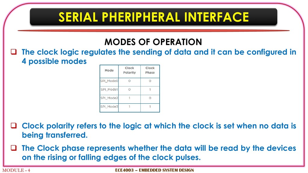
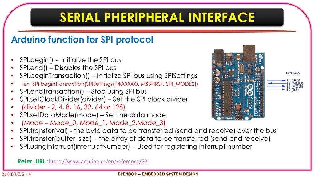
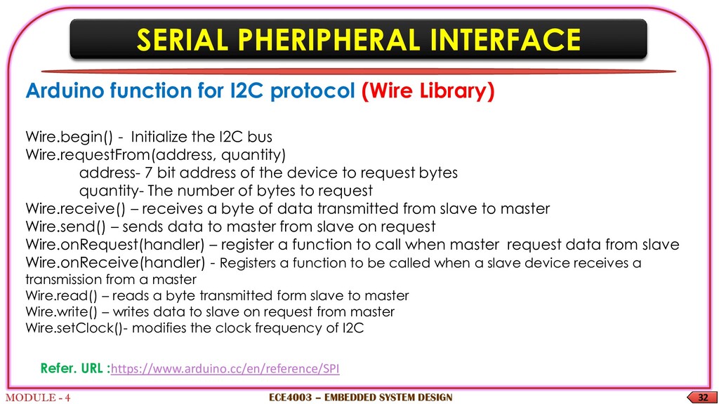
    DESIGN Arduino function for SPI protocol • SPI.begin() - Initialize the SPI bus • SPI.end() – Disables the SPI bus • SPI.beginTransaction() – Initialize SPI bus using SPISettings • ex: SPI.beginTransaction(SPISettings(14000000, MSBFIRST, SPI_MODE0)) • SPI.endTransaction() – Stop using SPI bus • SPI.setClockDivider(divider) – Set the SPI clock divider • (divider - 2, 4, 8, 16, 32, 64 or 128) • SPI.setDataMode(mode) – Set the data mode • (Mode – Mode_0, Mode_1, Mode_2,Mode_3) • SPI.transfer(val) - the byte data to be transferred (send and receive) over the bus • SPI.transfer(buffer, size) – the array of data to be transferred (send and receive) • SPI.usingInterrupt(interruptNumber) – Used for registering interrupt number Refer. URL :https://www.arduino.cc/en/reference/SPI
  39. SERIAL PHERIPHERAL INTERFACE MODULE - 4 Arduino- Serial Peripheral Interface

    - Master ECE4003 – EMBEDDED SYSTEM DESIGN #include <SPI.h> void setup (void) { Serial.begin(115200); //set baud rate to 115200 for UART digitalWrite(SS, HIGH); // disable Slave Select SPI.begin (); SPI.setClockDivider(SPI_CLOCK_DIV8);//divide the clock by 8 } void loop (void) { char c; digitalWrite(SS, LOW); // enable Slave Select, send test string for (const char * p = "Hello, world!\r" ; c = *p; p++) { //to send the string Hello, world!\r" and use the \r as flag to signal the slave that transfer is done. SPI.transfer (c); Serial.print(c); } digitalWrite(SS, HIGH); // disable Slave Select delay(2000); }
  40. SERIAL PHERIPHERAL INTERFACE MODULE - 4 ECE4003 – EMBEDDED SYSTEM

    DESIGN Arduino- Serial Peripheral Interface -Slave #include <SPI.h> char buff [50]; //stores the incoming values via SPI. volatile byte indx; //stores the index of the 8 bit volatile boolean process; //saves the current status of the transmission. void setup (void) { Serial.begin (115200); pinMode(MISO, OUTPUT); // have to send on master in so it set as output SPCR |= _BV(SPE); // turn on SPI in slave mode (SPCR - SPI control register – 8 bit register) indx = 0; // buffer empty SPE – enables SPI when 1 process = false; SPI.attachInterrupt(); // turn on interrupt } ISR (SPI_STC_vect) // SPI interrupt routine { byte c = SPDR; // read byte from SPI Data Register
  41. SERIAL PHERIPHERAL INTERFACE MODULE - 4 ECE4003 – EMBEDDED SYSTEM

    DESIGN Arduino- Serial Peripheral Interface -Slave if (indx < sizeof buff) { buff [indx++] = c; // save data in the next index in the array buff if (c == '\r') //check for the end of the word process = true; } } void loop (void) { if (process) { process = false; //reset the process Serial.println (buff); //print the array on serial monitor indx= 0; //reset button to zero } } Refer. URL : https://diyi0t.com/spi-tutorial-for-arduino-and-esp8266/
  42. INTER-INTEGRATED CIRCUIT MODULE - 4 INTRODUCTION  I2C is invented

    in 1989 by Philips semiconductor  It is a serial protocol with only two wire interface like UART  Widely used for short distance and intra-board communication  I2C has the best features of both SPI and UART protocols  It can support multi-master and multi-slave configuration ECE4003 – EMBEDDED SYSTEM DESIGN https://www.circuitbasics.com/basics-of-the-i2c-communication-protocol/
  43. INTER-INTEGRATED CIRCUIT MODULE - 4 INTRODUCTION  I2C protocol use

    only two pins Serial Data (SDA) and Serial Clock (SCL)  Data is transmitted bit by bit along SDA in I2C  SDA (Serial Data) – Bidirectional connection between master and slave  SCL (Serial Clock) – clock signal ECE4003 – EMBEDDED SYSTEM DESIGN
  44. INTER-INTEGRATED CIRCUIT MODULE - 4 INTRODUCTION  I2C is also

    a synchronous protocol, hence the output is synchronized using clock signal  Common clock signal is shares between master and slave  Master always controls the clock signal  Master device addresses the slave devices via SCL ECE4003 – EMBEDDED SYSTEM DESIGN
  45. INTER-INTEGRATED CIRCUIT MODULE - 4 HOW I2C WORKS  Data

    is transferred as messages in I2C  Messages are broken to frames of data  Each message contains a binary address frame of the slave and data frames  One or many data frames with data can be transferred in one message  The message has start and stop conditions, read, write, ACK & NACK bit between each data frame ECE4003 – EMBEDDED SYSTEM DESIGN
  46. INTER-INTEGRATED CIRCUIT MODULE - 4 HOW I2C WORKS ECE4003 –

    EMBEDDED SYSTEM DESIGN https://www.circuitbasics.com/basics-of-the-i2c-communication-protocol/
  47. INTER-INTEGRATED CIRCUIT MODULE - 4 HOW I2C WORKS  Start

    Condition: The SDA pin switches from high to low voltage level before the SCL pin switches from high to low  Stop Condition: The SDA pin switches from low to high voltage after SCL pin switches from low to high  Address Frame: 7 or 10 bit unique address is assigned to each slave for identifying when master wants to connect to it ECE4003 – EMBEDDED SYSTEM DESIGN
  48. INTER-INTEGRATED CIRCUIT MODULE - 4 HOW I2C WORKS  Read/Write

    Bit: This bit defines the state of master, whether it is sending data (low) or receiving data (high)  ACK/NACK Bit: Each frame is followed by a ACK bit.  If message is successfully received, an ACK bit is returned ECE4003 – EMBEDDED SYSTEM DESIGN
  49. INTER-INTEGRATED CIRCUIT MODULE - 4 STEPS OF I2C DATA TRANSMISSION

    ECE4003 – EMBEDDED SYSTEM DESIGN STEP-1: The master sets the start condition by setting all SDA pin to low before setting SCL pin https://www.circuitbasics.com/basics-of-the-i2c-communication-protocol/
  50. INTER-INTEGRATED CIRCUIT MODULE - 4 STEPS OF I2C DATA TRANSMISSION

    ECE4003 – EMBEDDED SYSTEM DESIGN STEP-2: The master sends 7 or 10 bit address to each slave with which it wants to communicate with, along with the read/write bit https://www.circuitbasics.com/basics-of-the-i2c-communication-protocol/
  51. INTER-INTEGRATED CIRCUIT MODULE - 4 STEPS OF I2C DATA TRANSMISSION

    ECE4003 – EMBEDDED SYSTEM DESIGN STEP-3:  After receiving address from master, slave compare the address with its own address  If the address matches, ACK bit is sent and SDA pin is switched to low  If address does not matches slave keeps the SDA pin high https://www.circuitbasics.com/basics-of-the-i2c-communication-protocol/
  52. INTER-INTEGRATED CIRCUIT MODULE - 4 STEPS OF I2C DATA TRANSMISSION

    ECE4003 – EMBEDDED SYSTEM DESIGN STEP-4: The master sends or receives the data frame https://www.circuitbasics.com/basics-of-the-i2c-communication-protocol/
  53. INTER-INTEGRATED CIRCUIT MODULE - 4 STEPS OF I2C DATA TRANSMISSION

    ECE4003 – EMBEDDED SYSTEM DESIGN STEP-5: After each successful data reception the receiving device sent a ACK bit https://www.circuitbasics.com/basics-of-the-i2c-communication-protocol/
  54. INTER-INTEGRATED CIRCUIT MODULE - 4 STEPS OF I2C DATA TRANSMISSION

    ECE4003 – EMBEDDED SYSTEM DESIGN STEP-6: To end the data transmission, the master sets the SCL pin high before setting SDA pin high https://www.circuitbasics.com/basics-of-the-i2c-communication-protocol/
  55. INTER-INTEGRATED CIRCUIT MODULE - 4 STEPS OF I2C DATA TRANSMISSION

    ECE4003 – EMBEDDED SYSTEM DESIGN Single Master with Multiple Slaves Multiple Master with Multiple Slaves https://www.circuitbasics.com/basics-of-the-i2c-communication-protocol/
  56. INTER-INTEGRATED CIRCUIT MODULE - 4  ADVANTAGES:  Only uses

    two wires  Supports multiple masters and slaves  Use chip addressing  ACK/NACK bit for successful transmission  it can work well with both slow and fast ICs.  DISADVANTAGES:  Slower data transfer rate than SPI  Clock speed limitation & power dissipation because of pull-up resistor  hardware complexity increases with multi master/slave configuration  Frame overhead due to ack bits and device address bits ECE4003 – EMBEDDED SYSTEM DESIGN
  57. SERIAL PHERIPHERAL INTERFACE 32 MODULE - 4 ECE4003 – EMBEDDED

    SYSTEM DESIGN Arduino function for I2C protocol (Wire Library) Wire.begin() - Initialize the I2C bus Wire.requestFrom(address, quantity) address- 7 bit address of the device to request bytes quantity- The number of bytes to request Wire.receive() – receives a byte of data transmitted from slave to master Wire.send() – sends data to master from slave on request Wire.onRequest(handler) – register a function to call when master request data from slave Wire.onReceive(handler) - Registers a function to be called when a slave device receives a transmission from a master Wire.read() – reads a byte transmitted form slave to master Wire.write() – writes data to slave on request from master Wire.setClock()- modifies the clock frequency of I2C Refer. URL :https://www.arduino.cc/en/reference/SPI
  58. INTER-INTEGRATED CIRCUIT MODULE - 4 ECE4003 – EMBEDDED SYSTEM DESIGN

    I2C – Arduino Interface Master read include <Wire.h> void setup() { Wire.begin(); // join i2c bus (address optional for master) Serial.begin(9600); // start serial for output } void loop() { Wire.requestFrom(8, 6); // request 6 bytes from slavedevice #8 while (Wire.available()) { // slave may send less than requested char c = Wire.read(); // receive a byte as character Serial.print(c); // print the character } delay(500); }
  59. INTER-INTEGRATED CIRCUIT MODULE - 4 ECE4003 – EMBEDDED SYSTEM DESIGN

    I2C – Arduino Interface Slave sender #include <Wire.h> void setup() { Wire.begin(8); // join i2c bus with address #8 Wire.onRequest(requestEvent); // register event } void loop() { delay(100); } // function that executes whenever data is requested by master // this function is registered as an event, see setup() void requestEvent() { Wire.write("hello "); // respond with message of 6 bytes // as expected by master }
  60. UNIVERSAL SERIAL BUS MODULE - 4 INTRODUCTION  Universal Serial

    Bus – Introduced to overcome the issues with different types of ports like serial port, parallel port, PS2, etc.…  Any type of device can be connected – printer, webcam, MP3player, cell phones, keyboard and mice  USB is the standard interface on almost all single boards computers, motherboards and embedded devices  USB is a very common port in all devices ECE4003 – EMBEDDED SYSTEM DESIGN
  61. UNIVERSAL SERIAL BUS MODULE - 4 INTRODUCTION  One device

    is connected as host and other device is connected as peripheral  When a USB drive is inserted to a computer, it act as peripheral and computer act as host device – Star local area network  Host device manages the peripheral using relevant driver software  USB ports can be extended using extension hubs i.e., one USB port can be extended to multiple ports (max 127 devices)  A number is assigned as address to the USB device (7 bit addressing) ECE4003 – EMBEDDED SYSTEM DESIGN
  62. UNIVERSAL SERIAL BUS MODULE - 4 INTRODUCTION  This address

    is dynamic and changes every time device is connected and uniquely used by the device  Each device contains endpoints/transfer types, i.e., collection of source and destination between host and peripheral  Endpoints operate either as input or output (Simplex mode)  It can be seen as interface between the hardware and firmware of the functioning device ECE4003 – EMBEDDED SYSTEM DESIGN
  63. UNIVERSAL SERIAL BUS MODULE - 4 INTRODUCTION  Pipe is

    a logical connection between the host and endpoints  The address, endpoint number and direction are used to determine the pipe in which data is travelling  A pipe is simply a data path between an endpoint and the controlling software  A special pipe is defined to connect to the zero endpoints called as default control pipe  Two types of pipe: Stream and message pipes  Enumeration : making peripheral device recognizable at host ECE4003 – EMBEDDED SYSTEM DESIGN
  64. UNIVERSAL SERIAL BUS MODULE - 4 USB TYPES ECE4003 –

    EMBEDDED SYSTEM DESIGN Type (USB) Speed Max power Cable configuration Availability 1.0 1.5Mbps 2.5 V Type A-B (Unidirectional) 1998 1.0 12Mbps 2.5 V Type A-B (Unidirectional) 1998 2.0 450Mbps 2.5 V Type A-B (Unidirectional) 2000 3.0 5Gbps 5 V Type A-B (Unidirectional) 2008 3.1 10Gbps 20 V Type c (bi directional) 2015 High Speed Full Speed Low Speed Super Speed Super Speed+
  65. UNIVERSAL SERIAL BUS MODULE - 4 HOW USB WORKS 

    Universal Serial Bus is serial data transmission protocol  Bytes of data are broken up and sent along the bus one bit at a time, with the LSB first  The data transfer in USB are done using packets. It can contain more than one packets.  A packet consist of SYNC(Synchronous)byte, PID, Content (data, address, etc.) , CRC, EOP. ECE4003 – EMBEDDED SYSTEM DESIGN
  66. UNIVERSAL SERIAL BUS MODULE - 4 HOW USB WORKS 

    Each packet is made up of a set of components called fields 1. An eight bit SYNC  8 bit long for USB 1.0, 32 bit for other types  used to synchronize the clock of host and peripheral  Last two bits indicated start of PID 2. The 8 bit Packet Identifier (PID)  4 bits – identify the type of packet and remaining 4 bits are 1's complement 4 bits acting as check bits 3. An address field (ADDR)  7- bit length specifies the address of device (max 127 devices) ECE4003 – EMBEDDED SYSTEM DESIGN
  67. UNIVERSAL SERIAL BUS MODULE - 4 HOW USB WORKS 

    Each packet is made up of a set of components called fields 4. 4 bit endpoint field (ENDP)  Allows maximum 16 possible endpoints 5. Cyclic Redundancy Check (CRC) is used for error detection on all fields except the PID  Token packet has 5 bit CRC  Data packets have 16 bit CRC 6. End of packet (EOP) 2 bit ECE4003 – EMBEDDED SYSTEM DESIGN
  68. UNIVERSAL SERIAL BUS MODULE - 4 USB PACKET TYPES 

    Token packet – In, Out, Setup  Data packet (1024 bytes) – Data0, Data1  Data2 and Mdata packets only for high speed modes  Maximum data payload size-8 bytes(low speed), 1023 bytes (Full speed), 1024(high speed) ECE4003 – EMBEDDED SYSTEM DESIGN Sync PID ADDR ENDP CRC EOP Sync (8) PID (8) Data CRC EOP
  69. UNIVERSAL SERIAL BUS MODULE - 4 USB PACKET TYPES 

    Handshake packet – Ack, Nack, Stall  Start of Frame packet ECE4003 – EMBEDDED SYSTEM DESIGN Token packet Data packet Handshake packet Sync PID EOP Sync PID Frame number CRC5 EOP
  70. UNIVERSAL SERIAL BUS MODULE - 4 HOW USB WORKS 

    To initiate the data transfer an I/O Request Packet (IRP) is send to appropriate pipe (IRP is a block of data)  Data is sent via bus in packets  Each packet consist of information regarding source, destination, data length and error detection information ECE4003 – EMBEDDED SYSTEM DESIGN
  71. UNIVERSAL SERIAL BUS MODULE - 4 HOW USB WORKS 

    Each packet should have maximum size except the last packet  If less than expected size packets is received than error is assumed  The pipe will cancel all the IRP until the problem is solved using software  If no error has occurred and still endpoint is busy then NAK will be send to wait for a while ECE4003 – EMBEDDED SYSTEM DESIGN
  72. UNIVERSAL SERIAL BUS MODULE - 4 TYPES OF DATA TRANSFER

    There are four basic types of USB data transaction: ECE4003 – EMBEDDED SYSTEM DESIGN USB data transfer types Control Bulk Interrupt Isochronous
  73. UNIVERSAL SERIAL BUS MODULE - 4 TYPES OF DATA TRANSFER

    There are four basic types of USB data transaction:  Control:  This type of data transaction is used by host to send query or command  Low speed- 8 byte, Full speed- 8-64 bytes and High speed- 64 bytes ECE4003 – EMBEDDED SYSTEM DESIGN
  74. UNIVERSAL SERIAL BUS MODULE - 4 TYPES OF DATA TRANSFER

     Interrupt:  This type of data transaction is used for small amount of data e.g. mice or keyboards.  It is a polled message from the host ECE4003 – EMBEDDED SYSTEM DESIGN
  75. UNIVERSAL SERIAL BUS MODULE - 4 TYPES OF DATA TRANSFER

     Bulk:  This USB protocol is used in large data transfer applications like printer  Data with variable length blocks are transmitted by host  Full speed device-64 bytes  High speed device- 512 bytes  CRC is used for integrity check and an acknowledgement is sent. ECE4003 – EMBEDDED SYSTEM DESIGN
  76. UNIVERSAL SERIAL BUS MODULE - 4 TYPES OF DATA TRANSFER

     Isochronous:  Isochronous data transfer is use to steam real time data like live audio streaming  It does not use any checking  Packet sizes can be up to 1024 bytes. ECE4003 – EMBEDDED SYSTEM DESIGN
  77. UNIVERSAL SERIAL BUS MODULE - 4 INTRODUCTION  Pros: 

    Plug and Play connectivity  Hot swapping  High data rates  Noise immunity  Widely available  Cons:  5 meters maximum distance  only Peer to Peer Communication is possible  Not always available on industrial/commercial devices ECE4003 – EMBEDDED SYSTEM DESIGN
  78. CONTROL AREA NETWORK MODULE - 4 INTRODUCTION  Controller Area

    Network (CAN) protocol is developed by Robert Bosch in 1986  CAN uses a integrated mechanism to handle different Electronic Control units (ECU) or nodes using a common cable  In CAN bus, ECU can be engine, airbag, audio system, etc.  A modern car can have up-to 70 ECUs  CAN is a broadcast type of bus and message based protocol  Serial half-duplex Asynchronous communication ECE4003 – EMBEDDED SYSTEM DESIGN
  79. CONTROL AREA NETWORK MODULE - 4 INTRODUCTION  CAN bus

    allows all ECUs to communicate with each other via a single bus  CAN bus has two wires- CAN low and CAN high  NEED FOR CAN:  Simple and low cost – Communicate via one single bus  Fully centralized – one point of entry  Extremely robust – towards electromagnetic interference and electric disturbance  Efficient – CAN frame has ID for prioritization ECE4003 – EMBEDDED SYSTEM DESIGN
  80. CONTROL AREA NETWORK MODULE - 4 INTRODUCTION ECE4003 – EMBEDDED

    SYSTEM DESIGN Pictorial view of the point to point wiring connection
  81. CONTROL AREA NETWORK MODULE - 4 INTRODUCTION  CAN protocol

    is a set of rules for transmitting and receiving messages in a network of electronic devices.  It is a method of communication used in automobiles to communicate between electronic devices like active suspension, ABS, gear control, lighting control, air conditioning, airbags, central locking etc.  Every electronic device is connected using a common serial bus to receive and transmit data using CAN protocol ECE4003 – EMBEDDED SYSTEM DESIGN
  82. CONTROL AREA NETWORK MODULE - 4 INTRODUCTION  The node

    must have hardware and software embedded in them to have data exchange  Host controller (ECU/MCU) is responsible for the functioning of the respective node.  CAN controller convert the messages in accordance with the CAN protocols for transmitting via CAN transceiver  CAN controller can either be connected separately or embedded inside the host controller ECE4003 – EMBEDDED SYSTEM DESIGN
  83. CONTROL AREA NETWORK MODULE - 4 ADVANTAGES  Low cost:

    They are cheap on bulk production  Reliable: Highly immune to EMI and excellent error detection and error handling  Flexibility: can be easily connected / disconnected  Good Speed: 1 MBit/s @ 40m bus length.  Multi-master communication  Fault Confinement  Broadcast capability ECE4003 – EMBEDDED SYSTEM DESIGN
  84. CONTROL AREA NETWORK MODULE - 4 CAN ARCHITECTURE  CAN

    uses the existing OSI reference model for data transmission  CAN protocol uses lower two layers of OSI physical layer and data link layer.  The System designer defined the functionality of remaining five layers according to needs  Host controller uses application layer of OSI model  CAN controller incorporate logical link control (LLC) and MAC medium access control of data link layer.  LLC allows filtering of messages by using unique ID ECE4003 – EMBEDDED SYSTEM DESIGN
  85. CONTROL AREA NETWORK MODULE - 4 CAN ARCHITECTURE  Once,

    framing is done it is followed by arbitration, error detection and acknowledgement handled by MAC layer  CAN trans-receiver takes care of encoding and decoding.  Finally CAN trans-receiver synchronizes with the CAN bus for message transmission ECE4003 – EMBEDDED SYSTEM DESIGN
  86. CONTROL AREA NETWORK MODULE - 4 HOW CAN PROTOCOL WORKS?

     Master-slave configuration is not supported in the CAN protocol architecture  Each node cannot access every other node for reading and writing data on CAN bus  Based on the availability of bus, CAN bus writes the CAN frame  A frame is defined structure, carrying sequence of bit or bytes of data  In CAN protocol predefined unique ID is used instead of destination address ECE4003 – EMBEDDED SYSTEM DESIGN
  87. CONTROL AREA NETWORK MODULE - 4 HOW CAN PROTOCOL WORKS?

     Every byte of information is defined in the CAN protocol  All nodes receive the CAN frame and based on the ID nodes decides whether to accept it or not  Highest priority message gets the bus access and low priority nodes will wait till the bus is available  Nodes can be added without re-programming ECE4003 – EMBEDDED SYSTEM DESIGN
  88. CONTROL AREA NETWORK MODULE - 4 MESSAGE FRAMING  Messages

    in CAN are sent in a format called frames. Framing of message is done by MAC sub layer of Data Link Layer.  There are two type of frames standard or extended. These frames can be differentiated on the basis of identifier fields.  A CAN frame with 11 bit identifier fields called Standard CAN and with 29 bit identifier field is called extended frame  Binary values in CAN protocol are termed as dominant (logic 0) and recessive (logic 1) bits. ECE4003 – EMBEDDED SYSTEM DESIGN
  89. CONTROL AREA NETWORK MODULE - 4 STANDARD CAN - MESSAGE

    FRAMING ECE4003 – EMBEDDED SYSTEM DESIGN Various fields in standard CAN SOF 11 bit identifier RTR IDE r0 DLC 0…8 byte data CRC ACK EOF IFS
  90. CONTROL AREA NETWORK MODULE - 4 STANDARD CAN - MESSAGE

    FRAMING  SOF - Start of Frame bit. It indicates start of message and used to synchronize the nodes on a bus. A dominant bit (logic 0) in the field marks the start of frame.  IDENTIFIER-It serves dual purpose, one to determine which node has access to the bus and second to identify the type of message.  RTR - Remote Transmission Request. It identifies whether it’s a data frame or a remote frame. RTR is dominant when it is a data frame and recessive when it is a remote frame ECE4003 – EMBEDDED SYSTEM DESIGN
  91. CONTROL AREA NETWORK 149 MODULE - 4 STANDARD CAN -

    MESSAGE FRAMING  IDE – Identifier Extension. It is used to specify the frame format. Dominant bit is for standard and recessive for extended frame.  R0 - Reversed bit. Not used currently and kept for future use.  DLC – Data Length Code. It is 4 bit data length code that contains the number of bytes being transmitted.  DATA – Used to store up to 64 data bits of application data to be transmitted. ECE4003 – EMBEDDED SYSTEM DESIGN
  92. CONTROL AREA NETWORK MODULE - 4 STANDARD CAN - MESSAGE

    FRAMING  CRC– Cyclic Redundancy Check. The 16-bit (15 bits plus delimiter) cyclic redundancy check (CRC) contains the checksum of the preceding application data for error detection.  ACK – Acknowledge (ACK) field. It compromises of the ACK slot and the ACK delimiter. When the data is received correctly the recessive bit in ACK slot is overwritten as dominant bit by the receiver. ECE4003 – EMBEDDED SYSTEM DESIGN
  93. CONTROL AREA NETWORK MODULE - 4 STANDARD CAN - MESSAGE

    FRAMING  EOF– End of Frame (EOF). The 7-bit field marks the end of a CAN frame (message) and disables  IFS - Inter Frame Space that specifies minimum number of bits separating consecutive messages  IFS provides the intermission between two frames and consists of three recessive bits known as intermission bits. This time allows nodes for internal processing before the start of next frame. ECE4003 – EMBEDDED SYSTEM DESIGN
  94. CONTROL AREA NETWORK MODULE - 4 EXTENDED CAN - MESSAGE

    FRAMING ECE4003 – EMBEDDED SYSTEM DESIGN Various fields in EXTENDED CAN SOF 11-bit identifier SRF IDE 18-bit Identifier RTR r1 r0 DLC 0…8 Bytes Data CRC ACK EOF IFS
  95. CONTROL AREA NETWORK MODULE - 4 EXTENDED CAN - MESSAGE

    FRAMING  It is same as 11-bit identifier with some added fields  SRR- Substitute Reverse Request- always transmitted as a recessive bit to make sure standard data frame always have the same priority  R1- It is another bit not used currently and kept for future use. ECE4003 – EMBEDDED SYSTEM DESIGN
  96. CONTROL AREA NETWORK MODULE - 4 MESSAGE FRAME - TYPES

     There are four different frames which can be used on the bus.  Data frames- most commonly used frame for data transmission from one node to another node  Data Frames contains Arbitration Fields, Control Fields, Data Fields, CRC Fields, a 2-bit Acknowledge Field and an End of Frame.  Remote frames – seeks permission for data transmission from another node  It is similar to data frame without data field and RTR bit is recessive. ECE4003 – EMBEDDED SYSTEM DESIGN
  97. CONTROL AREA NETWORK MODULE - 4 MESSAGE FRAME - TYPES

     Error frames – If transmitting or receiving node detects an error, it will immediately abort transmission and send error frame consisting of an error flag made up of dominant bits and error flag delimiter made up of eight recessive bits. ECE4003 – EMBEDDED SYSTEM DESIGN 0……12 8 Error Flag Field Error Delimiter Field Error Passive Error Active Field within DATA or Error Frame Error Frame Interface space or overload frame
  98. CONTROL AREA NETWORK MODULE - 4 MESSAGE FRAME - TYPES

     Overload frame-It is similar to error frame but used for providing extra delay between the messages. An Overload frame is generated by a node when it becomes too busy and is not ready to receive. ECE4003 – EMBEDDED SYSTEM DESIGN
  99. CONTROL AREA NETWORK MODULE - 4  Future of CAN

    bus  Need to accommodate increasing advanced vehicle  Role of Internet of Things in vehicles  Development of autonomous vehicles  The advancement of cloud computing  To address security issues  Vehicle telematics ECE4003 – EMBEDDED SYSTEM DESIGN
  100. PERIPHERAL COMPONENT INTERCONNECT MODULE - 4 INTRODUCTION  PCI stands

    for Peripheral Component Interconnect  Processor independent bus that can function as peripheral bus  PCI is often used for connecting sound cards, network cards and video cards with system  It is developed by intel in 1993  PCI is mostly used in computer system to connect the peripheral components with motherboard ECE4003 – EMBEDDED SYSTEM DESIGN
  101. PERIPHERAL COMPONENT INTERCONNECT MODULE - 4 FEATURES  Synchronous architecture

     Large bandwidth for high speed  Operated at 66 and 33 MHZ  It follows 64 bit addressing  Plug & play  It supports variety of microprocessor based configuration  Hot-swappable and hot-plug-ability ECE4003 – EMBEDDED SYSTEM DESIGN
  102. PERIPHERAL COMPONENT INTERCONNECT MODULE - 4 FEATURES  PCI supports

    master and slave configuration  Host CPU acts as master and associated device become slave  It has three spaces, memory, IO and configuration space  The memory and IO act as work space and configuration act as plug and play space  PCI connect through a “bridge” chip to CPU ECE4003 – EMBEDDED SYSTEM DESIGN
  103. PERIPHERAL COMPONENT INTERCONNECT MODULE - 4 FEATURES  PCI has

    49 mandatory signal lines and 52 optional signal lines for PCI  Functional sub-groups  System pin  Address and data pins  Interface control pins  Arbitration pins  Error reporting pins  Interrupt pins  Cache-support pins  64-bit bus extension pins  JTAG or boundary scan pin ECE4003 – EMBEDDED SYSTEM DESIGN
  104. PERIPHERAL COMPONENT INTERCONNECT MODULE - 4 FEATURES  PCI commands

    to I/O device  Special I/O instructions – device address and command word  Memory mapped instructions – read/write operations to the address space  OS and I/O – OS should be aware of the current operation  Polling – status register  I/O interrupt ECE4003 – EMBEDDED SYSTEM DESIGN
  105. PERIPHERAL COMPONENT INTERCONNECT MODULE - 4  Advantages  PCI

    handles devices or gadgets with more than 5V  Different PCI bus can be used in same system  Disadvantages  PCI graphics card cannot get into system  PCI does not support Pipeline ECE4003 – EMBEDDED SYSTEM DESIGN
  106. ZIGBEE MODULE - 4 INTRODUCTION ECE4003 – EMBEDDED SYSTEM DESIGN

     ZigBee protocol is mostly used in the power constraint short distance communication  Why another short range communication protocol ?  Bluetooth  Wi-Fi  ZigBee is specially build control and sensor applications  ZigBee is a standard with- very low cost, low power device, low data rate and short range communications
  107. ZIGBEE MODULE - 4 INTRODUCTION ECE4003 – EMBEDDED SYSTEM DESIGN

     Most commonly used standard in WSN, IoT  Open source standard developed by ZigBee Alliance  It works on IEEE 802.15.4 standard for wireless personal area networks  ZigBee operates at 868 MHz (Europe), 902-928MHz (US & Australia) and 2.4 GHz (worldwide) frequencies  Data rate of 250 kbps for low data rate applications
  108. ZIGBEE MODULE - 4 ECE4003 – EMBEDDED SYSTEM DESIGN 

    ZigBee devices can cover a distance range between 10-100 meters.  It supports master-slave configuration or master-master configuration  ZigBee architecture consist of coordinator, router and end device  ZigBee supports star, tree and mesh topologies  Modes of operation – Beacon and Beacon less
  109. ZIGBEE MODULE - 4 ECE4003 – EMBEDDED SYSTEM DESIGN 

    Coordinator  Root of network  One coordinator in each network  Performs channel selection, assigning node ID, allocation of unique address  Routers  Intermediate node between coordinator and end node  Route traffic between different nodes  Allows other end devices to join network
  110. ZIGBEE MODULE - 4 ECE4003 – EMBEDDED SYSTEM DESIGN 

    End Node  sleep mode to increase battery efficiency  All traffic to end device is first routed to parent node
  111. ZIGBEE MODULE - 4 ECE4003 – EMBEDDED SYSTEM DESIGN 

    Channel Access  The coordinator assigns only one channel to the network  Methods of channel access  Contention based - need not synchronized and used CSMA  CSMA: Channel goes to receive mode and check for any signal, if no signal is detected then it will start data transmission or else wait for a random period of time  Contention free - Allocates specific time slot to each device  GTS- Guaranteed Time Slot
  112. ZIGBEE MODULE - 4 ECE4003 – EMBEDDED SYSTEM DESIGN ZigBee

    characteristics  Low power consumption – extended battery life  Low data rate – 200-250 kbps  Wi-Fi- 11 Mbps, Bluetooth – 1 Mbps  Short range  75-100 meter indoor  Up to 300 meters outdoor  Network join time- 30 sec  Large and small networks – 65000 (theoretical)  Low cost  Uses AES encryption for security
  113. ZIGBEE MODULE - 4 ECE4003 – EMBEDDED SYSTEM DESIGN IEEE

    802.15.4 PHY packet structure Preamble – synchronization Start of packet delimiter PHY header – PSDU length PSDU – data field Preamble (32 ) Start of packet delimiter (8) PHY header (8) PHY Service Data Unit (PSDU) (0-1016 bits)
  114. ZIGBEE MODULE - 4 ECE4003 – EMBEDDED SYSTEM DESIGN IEEE

    802.15.4 MAC frame format  Data frame  Beacon frame  Acknowledgement frame  Command frame General MAC Frame Format Octets : 2 1 0/2 0/2/8 0/2 0/2/8 Variable 2 Frame Control Sequence number Destination PAN identifier Destination Address Source PAN Identifier Source Address Frame payload Frame Check Sequence MAC header MAC Payload MAC footer
  115. ZIGBEE MODULE - 4 ECE4003 – EMBEDDED SYSTEM DESIGN IEEE

    802.15.4 MAC frame format - Beacon Frame Format Octets : 2 1 4 or10 2 Variable variable Variable 2 Frame control Beacon sequence number Source address information Super frame specification GTS field Pending address field Beacon payload Frame check sequence MAC header MAC payload MAC Footer • The beacon frame is transmitted periodically by the PAN coordinator. • It provides information about the network management through the super frame and GTS fields. • It also synchronizes the network devices and indicates the proper communication period for them.
  116. ZIGBEE MODULE - 4 ECE4003 – EMBEDDED SYSTEM DESIGN IEEE

    802.15.4 MAC frame format Command Frame Format Octets: 2 1 4 to 20 1 Variable 2 Frame control Data Sequence number Address information Command type Command payload Frame Check sequence MAC header MAC payload MAC Footer • Useful for communication between the network devices. • The command identifier specifies actions like association, disassociation, and data, GTS or beacon request.
  117. ZIGBEE MODULE - 4 ECE4003 – EMBEDDED SYSTEM DESIGN IEEE

    802.15.4 MAC frame format Data Frame Format Acknowledgment Frame Format Octets : 2 1 4 to 20 Variable 2 Frame Control Data Sequence number Address information Data payload Frame check sequence MAC header MAC payload MAC footer Octets : 2 1 2 Frame control Data Sequence Number Frame Check sequence MAC header MAC footer
  118. ZIGBEE MODULE - 4 ECE4003 – EMBEDDED SYSTEM DESIGN Parameters

    Description Radio Technology IEEE 802.15.4 Frequency band/Channels 2.4 GHz (ISM band) 16-channels (2 MHz wide) Data rate 250 Kbits/sec Encryption support AES-128 at Network Layer Communication range 75-100 meter indoor 300+ meters line of sight Network size (Theoretical) Up to 65,000
  119. ZIGBEE MODULE - 4 ECE4003 – EMBEDDED SYSTEM DESIGN 

    Simple setup and maintenance  Low power consumption, ideal for long lifetime devices  It can be used for lighting, security, appliance and home access  Low latency and low data rate  It offers network flexibility and scalability Advantages of ZigBee Protocol
  120. ZIGBEE MODULE - 4 ECE4003 – EMBEDDED SYSTEM DESIGN Arduino

    Coding for Zigbee interface #include <SoftwareSerial.h> SoftwareSerial XBee(2, 3); void setup() { XBee.begin(9600); Serial.begin(9600); } void loop() { if (Serial.available()) { XBee.write(Serial.read()); } if (XBee.available()) { Serial.write(XBee.read()); } }
  121. BLUETOOTH MODULE - 4 INTRODUCTION  Bluetooth is a transceiver

    protocol works in 2.4GHz wireless link  It’s a secure protocol, and it’s perfect for short-range, low- power, low-cost, wireless transmissions  Zigbee and Wi-Fi both uses same bandwidth  Bluetooth is a dynamic standard where devices can automatically find each other, establish connections, and discover what they can do for each other on an ad hoc basis.  Bluetooth networks can be referred as piconet and scatternet  It use a master/slave model ECE4003 – EMBEDDED SYSTEM DESIGN
  122. BLUETOOTH MODULE - 4 INTRODUCTION  A single master device

    can be connected to up to seven different slave devices  The master coordinates communication throughout the piconet. It can send data to any of its slaves and request data from them as well  Slaves are only allowed to transmit to and receive from their master. They can’t talk to other slaves in the piconet  Every single Bluetooth device has a unique 48-bit address, commonly abbreviated BD_ADDR. This will usually be presented in the form of a 12-digit hexadecimal value ECE4003 – EMBEDDED SYSTEM DESIGN
  123. BLUETOOTH MODULE - 4 INTRODUCTION ECE4003 – EMBEDDED SYSTEM DESIGN

    Examples of Bluetooth master/slave piconet topologies.
  124. BLUETOOTH 171 MODULE - 4 ARCHITECTURE ECE4003 – EMBEDDED SYSTEM

    DESIGN Applications Others TCS SDP RFCOMM Logical Link Control and Adaptation Protocol (L2CAP) Link Manager Protocol (LMP) Baseband Radio Host Controller
  125. BLUETOOTH 172 MODULE - 4 ARCHITECTURE  Radio: This layer

    defines the requirements for a transceiver to operate in the 2.4 GHz ISM band such as frequency bands, frequency hopping specifications, and modulation techniques.  Baseband: The Baseband layer describes the specification of the Bluetooth Link Controller (LC), and carries baseband protocol. It defines the addressing scheme, packet frame format, timing, and power control algorithms. Two types of link can be created in baseband are ACL and SCO. ECE4003 – EMBEDDED SYSTEM DESIGN
  126. BLUETOOTH MODULE - 4 Two types of link between master

    and slave  Asynchronous Connection Less (ACL)  Packet switched data  Slave can have only one ACL link to master  Used for correct delivery over fast delivery  Maximum data rate of 721 kbps  Synchronous Connection Oriented (SCO)  Real time data transmission  Damaged packet cannot be retransmitted  Data rate of 64 kbps ECE4003 – EMBEDDED SYSTEM DESIGN
  127. BLUETOOTH MODULE - 4 ARCHITECTURE  LMP: Used by the

    Link managers for link set-up and control. The other main functions of LMP are device authentication, message encryption, and negotiation of packet sizes.  Host Controller Interface (HCI): HCI provides a command interface to the Baseband LC and Link Manager, to access hardware status and control registers.  L2CAP: Logical Link Control and Adaptation Protocol (L2CAP) supports higher level protocol multiplexing, packet segmentation and reassembly, and also conveys the QoS. ECE4003 – EMBEDDED SYSTEM DESIGN
  128. BLUETOOTH MODULE - 4 ARCHITECTURE  RFCOMM: The RFCOMM protocol

    provides emulation of serial ports over the L2CAP protocol.  SDP: The Service Discovery Protocol (SDP) provides a means for applications to discover, which services are provided by or available through a Bluetooth device  TCS: telephony control protocol for telephony service  Applications: This includes the application profiles that allow the user to interact with the Bluetooth applications. ECE4003 – EMBEDDED SYSTEM DESIGN
  129. BLUETOOTH MODULE - 4 Access code (AC)  Used for

    packet identification  Once packet is received, receiver in piconet will compare the incoming signal with AC, if any mismatch is found packet will be ignored  72 bit AC is derived from master identity  It is used for synchronization  Three types  Channel AC – targets piconet ID  Device AC – individual devices  Inquiry AC – used during pairing ECE4003 – EMBEDDED SYSTEM DESIGN Access Code Header Data 72 bits 54 bits 0-2744 bits Preamble (4) Synchronisation (64) Trailer (4) Header Payload body CRC Data - contains data or control information from upper layer Header – identifies logical channel Payload body – contains user data CRC- 16 bit checksum
  130. BLUETOOTH MODULE - 4 Header  Address – it can

    address up to 7 slave devices, if it is 0, then messages will broadcasted  Type – defines type of incoming data ACL – Data medium (DM) or Data High (DH) SCO - Data Voice (DV) and High Quality Voice (HV)  12 types of packet for each SCO and HV  4 common control packets  Flow- 1 bit flow control  ARQN – 1 bit acknowledgement  SEQN – 1 bit sequential numbering scheme for packet ordering  HEC – Header error check  Header = 3 X 18 bits = 54 bits ECE4003 – EMBEDDED SYSTEM DESIGN 3 bits 4 bits 1 bits AM_ADDR Type Flow ARQN SEQN HEC 1 bits 1 bits 8 bits
  131. BLUETOOTH MODULE - 4 BONDING AND PAIRING  When two

    Bluetooth devices want to connect, they can be bonded together.  Bonded devices automatically establish a connection whenever they’re close enough.  Bonds are created through a process called pairing.  On paring devices share their addresses, names, and profiles, and they are stored in memory.  The also share a common secret key, which allows devices to bond in future whenever required. ECE4003 – EMBEDDED SYSTEM DESIGN
  132. BLUETOOTH MODULE - 4 BONDING AND PAIRING  Pairing requires

    an authentication process to establish connection between devices.  Sometimes pairing is a simple “Just Works” operation, where the click of a button is all it takes to pair (this is common for devices with no UI, like headsets).  Older, legacy (v2.0 and earlier), pairing processes involve the entering of a common PIN code on each device. The PIN code can range in length and complexity from four numbers (e.g. “0000” or “1234”) to a 16-character alphanumeric string. ECE4003 – EMBEDDED SYSTEM DESIGN
  133. BLUETOOTH MODULE - 4 CONNECTION PROCESS  Creating a Bluetooth

    connection between two devices is a multi-step process involving three progressive states.  Step-1 Inquiry: If two Bluetooth devices know absolutely nothing about each other, one must run an inquiry to try to discover the other  On receiving the inquiry the device which listens to such a request will send back address, name and other information ECE4003 – EMBEDDED SYSTEM DESIGN
  134. BLUETOOTH MODULE - 4 CONNECTION PROCESS  Step-2 Paging (Connecting)

    – Paging is the process of forming a connection between two Bluetooth devices.  Step-3 Connection – After a device has completed the paging process, it enters the connection state.  The mode of operation of device is decided in connection phase ECE4003 – EMBEDDED SYSTEM DESIGN
  135. BLUETOOTH MODULE - 4 CONNECTION MODES  Active Mode –

    regular connected mode, where device send and receive data ( regular connection up-to 7 devices)  Sniff Mode – power saving mode, less active mode (frees slave for predetermined period of time, recurring fixed time slot)  Hold Mode – temporary mode, device will be sleeping for a particular period of time (frees slave for predetermined period of time, one time slot)  Park Mode – sleep mode with infinite time, slave will wake only if master tells it to wake up (maximum of 255 devices can be added) ECE4003 – EMBEDDED SYSTEM DESIGN
  136. BLUETOOTH MODULE - 4 POWER CLASSES  The transmit power

    determines the range of a Bluetooth module and it is defined by its power class.  There are three defined classes of power: ECE4003 – EMBEDDED SYSTEM DESIGN Class Number Max Output Power Max Output Power Max Range Class 1 20 dBm 100 mW 100 m Class 2 4 dBm 2.5 mW 10 m Class 3 0 dBm 1 mW 10 cm
  137. BLUETOOTH MODULE - 4 HC05 – BLUETOOTH MODULE  HC‐05

    module is an easy to use Bluetooth SPP (Serial Port Protocol) module, designed for transparent wireless serial connection setup.  The HC-05 Bluetooth Module can be used in a Master or Slave configuration, making it a great solution for wireless communication.  This serial port Bluetooth module is fully qualified Bluetooth V2.0+EDR (Enhanced Data Rate) 3Mbps modulation with complete 2.4GHz radio transceiver and baseband. ECE4003 – EMBEDDED SYSTEM DESIGN
  138. BLUETOOTH MODULE - 4 HC05 – BLUETOOTH MODULE  The

    Bluetooth module HC-05 is a MASTER/SLAVE module. By default the factory setting is SLAVE.  The Role of the module (Master or Slave) can be configured only by AT COMMANDS.  Master module can initiate a connection to other devices. The user can use it simply for a serial port replacement to establish connection between MCU and GPS, PC to your embedded project, etc. ECE4003 – EMBEDDED SYSTEM DESIGN
  139. BLUETOOTH MODULE - 4 HC05 – BLUETOOTH MODULE  Hardware

    Features  Up to +4 dBm RF transmit power.  3.3 to 5 V I/O.  PIO(Programmable Input/Output) control.  UART interface with programmable baud rate.  With integrated antenna.  Software Features  Slave default Baud rate: 9600, Data bits:8, Stop bit:1,Parity:No parity.  Auto‐connect to the last device on power as default.  Permit pairing device to connect as default.  Auto‐pairing PINCODE:”1234” as default ECE4003 – EMBEDDED SYSTEM DESIGN
  140. BLUETOOTH MODULE - 4 HC05 – BLUETOOTH MODULE – Arduino

    ECE4003 – EMBEDDED SYSTEM DESIGN #define ledPin 7 int state = 0; void setup() { pinMode(ledPin, OUTPUT); digitalWrite(ledPin, LOW); Serial.begin(38400); } void loop() { if(Serial.available() > 0){ // Checks whether data is comming from the serial port state = Serial.read(); // Reads the data from the serial port } if (state == '0') { Write a program to control a LED connected at Pin 7 of Arduino through command send by Bluetooth supported mobile device.
  141. BLUETOOTH MODULE - 4 HC05 – BLUETOOTH MODULE – Arduino

    ECE4003 – EMBEDDED SYSTEM DESIGN digitalWrite(ledPin, LOW); // Turn LED OFF Serial.println("LED: OFF"); // Send back, to the phone, the String "LED: ON" state = 0; } else if (state == '1') { digitalWrite(ledPin, HIGH); Serial.println("LED: ON");; state = 0; } }