Upgrade to Pro — share decks privately, control downloads, hide ads and more …

-Tokyo Digital Twin Project 2021- Demonstration 02 Report

data_rikatsuyou
June 21, 2022
450

-Tokyo Digital Twin Project 2021- Demonstration 02 Report

data_rikatsuyou

June 21, 2022
Tweet

Transcript

  1. 1.Background and Overview 2.Area 3.High-precision 3D model 4.Underground Measurement 5.Verification

    of Business Efficiency 6.Reflection on the Tokyo Met. Digital Twin 3D Viewer 7.Results and Issues 8.Future Directions Contents 1
  2. 3 Background Accurate location information of facilities and areas of

    excavations lead to pre-verification and recognition of hazards during constructions, realizing a safe and secure life for Tokyo residents. High accuracy of location identification using high-precision 3D skeletal spatial information is needed. ◼ Location information of underground buried objects (positional relationships) is not accurately known. ◼ If a construction is carried out based on ambiguous location information, accidents may occur. ◼ On underground, there are buried materials owned by various managers (both public and private sectors). Sophistication of buried object management operations by increasing the accuracy of locating detection is necessary.
  3. 4 Goal and Overview Overview ◼ Location information of underground

    buried objects owned by public or private sectors, which includes water, sewage, electric power, gas, and telecommunications facilities, were identified and corrected. ◼ The high-precision 3D models were created, by using high-precision 3D skeletal spatial information of facility drawings of underground buried objects. ◼ Using an array-type-radar-equipped survey equipment, the location of underground facilities were measured onsite. The accuracy of the 3D models created based on the drawings and those created by the measurements was compared. ◼ The improvement of the owners’ business operation, such as inquiries and negotiations, were verified by using the high-precision 3D models. Goal ◼ Realizing a safe, secure, and comfortable life by ➢ improving the efficiency of the management of underground buried objects ➢ reducing the amount of equipment accidents during underground construction through the advancement of business operation.
  4. 6 Area The North Exit area of JR Kinshicho Sta.

    was selected as demonstration area (c)INCREMENT P CORPORATION License number PL1702 Unauthorized reproduction of map data for purposes other than those stipulated is prohibited. Demonstration area The demonstration area was determined based on the status of buried structures maintenance.
  5. 7 Area Area Reasons for selection The North Exit area

    of JR Kinshicho Sta. The conditions required for demonstration are satisfied ◼ Kinshicho has a good GPS environment with no tall buildings in the vicinity ◼ Excellent flatness of the area, making it relatively easy to search for buried objects ◼ The sidewalks are wide enough to ensure safety during measurements ◼ The grid of roads makes it easy to determine the status of facilities laid out. The area has both of old and new equipments ◼ In order to verify differences between drawings and measurements, areas where differences between the two may be exist are desirable. ◼ Kinshicho is a mix of redeveloped and undeveloped areas, with a mixture of old and new facilities The existence of the private sectors’ data of underground buried objects data is already proved ◼ Prior negotiation with telecommunications, electric power, and gas company representatives confirms the existence of data. Kinshicho area meets the necessary conditions for the demonstration, e.g. GPS environment and flatness.
  6. 8 <Appendix> Height of Buildings and GPS Open sky environment

    is necessary in terms of ensuring GPS accuracy. (1)Intentional Accuracy Reduction by the U.S. Government = SA(Selective Availability) *Lifted in May 2000 (2) Clock error of GPS satellites (3) Errors in satellite orbit information (4)Atmospheric delay (ionosphere, troposphere) (5) Reflections from buildings and mountains (multipath) (6) Receiver clock error (7)Other noise or signal attenuation (8) System failure (9) Insufficient number of satellite placements and supplements [No. 1 error factor]. Source: https://www.ne.jp/asahi/nature/kuro/HGPS/principle_gps.htm (Accessed June 15, 2021) Multipath refers to the fact that radio waves not only arrive in a straight line, but also reflect off mountains, buildings, etc., and propagate through multiple routes. Reflected radio waves cause a slight delay before reaching their destination, and the amount of delay is measured as "far (distance) away," which is one of the factors that disrupt accurate positioning. Source: 内閣府「マルチパス」── 何がいけないの?」 (https://qzss.go.jp/column/multipath_160704.html)(Accessed j June 15, 2021) Linkit「衛星測位(GPS・みちびき)の誤差の原因と精度向上の方法を解説」(https://linkit.access- company.com/post2414/)(Accessed j June 15, 2021) 工学院大学 新技術説明会「高層ビル群環境下でも 高測位精度を実現する リレー型GPS」 ( https://shingi.jst.go.jp/var/rev0/0001/0624/2019_kogakuin_1.pdf ) GPS positioning requires signals from at least four GPS satellites for positioning. In urban areas, obstacles such as high-rise buildings can reduce the number of GPS satellites to less than four. Causes of GPS errors Number of satellite supplements Effect of multipath GPS receiver GPS satelite
  7. 9 <Appendix> Height of Buildings Kinshicho is the area with

    almost no tall buildings. Sumida City, Tokyo (Kinshicho)
  8. 10 <Appendix> Height of Buildings Shibuya City Chiyoda City (Daimaruyu)

    Shinjuku City (Nishi-Shinjuku) Toshima City (Ikebukuro) Other areas in Tokyo are more challenging in this demonstration because of the existence of tall buildings.
  9. ◼ Converting data in different formats (paper, raster, CAD) provided

    by various organizations and acquired as 2D vector data. ◼ Obtain and assign height information by referring to longitudinal and cross-sectional drawings in order to create 3D models. ◼ Acquire and assign information such as model and dimensions from equipment drawings that reproduce the shape of the equipment. 12 Conversion of Data Format ②Data conversion ③ Vecto- rization ④ Height info. ⑤Attribute info. Scan Format conver- sion Align- ment based on high- precision 3D skeletal space infor- mation Vectori- zation Longitu- dinal View Depth information is assigned at specific locations with longitudinal and cross- sectional views. ①Data CAD data Raster data paper GIS data The datum provided by the various organizations were unified in a single format. 2D position integration procedure Plan View Net drawing Attribute information is assigned according to the facility drawings of each organization.
  10. 13 Data integration environment Water supply Electricity Sewage ✓ Plane

    view ✓ Longitudinal view ✓ Net drawing ✓ Equipment Drawing Gas Communication High-precision electronic map (X,Y,Z) Equipment data GIS software (ArcGIS Pro) ◼ 3D city model data of “PLATEAU” from Association for Promotion of Infrastructure Geospatial Information Distribution is downloaded and imported into the data construction environment as GIS data. ◼ The data format is converted to GIS data. ◼ "Building" and "Topography (undulations)" are used. An environment to import and integrate underground facilities and 3D city models is developed. A data integration environment was built on a GIS software. Preparation of data construction environment 3D city model data capture
  11. 14 3D Modeling Displaying Multiple pipelines Step3 ◼Information necessary for

    reproducing the shape of equipment (model, dimensions, etc.) was given, and the pipeline thickness was displayed. Displaying pipeline thickness Step2 ◼2D vector data was converted into 3D model data based on height information. ◼Visual classification of each company was possible with coloring. Assigning Height Infor- mation Step1 (Source)エヌ・ティ・ティ・インフラネットHP 用語集(https://www.nttinf.co.jp/service/glossary.html)(Accessed November 24, 2021 ) The 2D datum were converted to 3D model in 3 steps. ◼Multiple conduits were shown (Electric power and telecommunications fall under this category). Multiple pipeline
  12. 15 3D Modeling The 3D models of underground structures were

    constructed by integrating datum from the various companies. 3D model of underground buried objects
  13. 16 Issues (1/4) Process Issues Solution Desirable Goal Data collec-

    tion Request ◼ Suppliers manage the data as GIS data in their own format. ◼ Map is digitized from paper ◼ Format conversion ◼ Managed by suppliers as GIS data in a common format Agreements and contracts ◼ No infrastructure to share highly confidential data among suppliers. ◼ Limited to the verification area, with individual consent from equipment suppliers. ◼ Build an infrastructure to share highly confidential data among equipment suppliers. Data conver- sion (Proces- sing) Digitizing map data (Paper→Image →Map Overlay) ◼ The present work of the equipment supplier does not require reference points, so there are no reference points on the paper drawings provided. ◼ Absolute location information of facilities is superimposed on level 500 accuracy* map data, and map digitization is performed in consideration of the balance of buried facilities in the entire verification area. * 25cm accuracy, the same as map data used for road ledger maintenance ◼ Development of a system to establish a reference point that can be shared among equipment suppliers. *Aligning positions with the coordinates of a reference point in the same coordinate reference system Digitizing map data (Equipment Drawing) ◼ There are drawings that cannot be drawn accurately because the scale of the printed paper drawing is significantly different from the scale of the map digitizing map. ◼ Drawing based on assumptions from peripheral equipment ◼ Match of three scales (1) drafting work for equipment data (2) printed paper drawings (3) map digitizing maps Issues, measures and desirable goals were comprehensively organized along with the 3D modeling process.
  14. 17 Issues (2/4) Process Issues Solution Desirable Goal Data conve-

    rsion (Proces- sing) Format Conversion (Electronic → Electronic) ◼ Facilities suppliers manage the data as GIS data in their own format. ◼ Analyze CSV and fixed-length data received from equipment suppliers and convert to general GIS data ◼ Managed by equipment suppliers as GIS data in a common format Alignment ◼ Old history of location information management by equipment suppliers for their own equipment, with some management using the old geodetic system. ◼ Geodetic system conversion (discovered during 3D modeling work) ◼ Provided in the current geodetic system (JGD2011) (If difficult, specify the geodetic system used) Data Assign- ment and Organi- zation Height information ◼ Equipment suppliers manage equipment data in terms of surface elevation (relative depth), which causes a discrepancy between the real world and the 3D model ◼ Depth is not controlled in some areas by the equipment supplier. ◼ JPGIS, the standard specification for general GIS data, only defines elevation. ◼ 3D modeling with the ground surface elevation as it is (* because there is no problem for the purpose of "checking the degree of influence at the time of excavation work") ◼ 3D modeling based on assumptions and relative location information based on front-back relationships with surrounding facilities, and uniform settings ◼ No special support because GIS application supports surface elevation ◼ Promote unification of industry specifications for depth (height) for use applications (elevation or ground level) with a view to digital twinning
  15. 18 Issues (3/4) Process Issues Solution Desirable Goal Data Assign-

    ment and Organi- zation Attribute informati on ◼ Facilities suppliers manage the data as GIS data in their own format. ◼ Textual information embedded as graphics in paper drawings is significantly less readable. ◼ Conversion to general GIS data ◼ Manual input with visual confirmation and supplemental input based on the back and forth relationship with surrounding equipment ◼ Managed by equipment suppliers as GIS data in a common format Constructio n of 3D model on the ground Data conver- sion (CAD →GIS) ◼ CAD's x- and y-coordinate axes are opposite to those of GIS, so there are no GIS applications that can display accurate locations without modification. ◼ Converted to general GIS data by swapping x and y coordinates ◼ Provide GIS data that can be smoothly displayed in 3D using common GIS applications Construc- tion of 3D model of the base- ment Display of Multi- factor ◼ Facilities contractors are only managing equipment lines and not one by one. ◼ Referring to the attribute information (number of strips, number of steps, etc.) of the equipment line, the display is forced to disregard work efficiency. ◼ Can switch between multi-factor and simple expressions depending on the use case Display of 3D model Viewer ◼ Viewer to share facility information with parties involved in negotiation ◼ Share standalone viewer screen ◼ Build a data distribution infrastructure to share highly confidential data among equipment suppliers. Legend display ◼ The free 3D viewer cannot display a legend of the tube colors on the GIS. ◼ Provided on a separate sheet to avoid operation. ◼ Changed to a viewer that can display a legend on the GIS
  16. 19 Issues (4/4) Process Issues Solution Desirable Goal Constructi on

    of 3D model on the ground Data conversi on (CAD→ GIS) ◼ CAD's x- and y-coordinate axes are opposite to those of GIS, so there are no GIS applications that can display accurate locations without modification. ◼ Converted to general GIS data by swapping x and y coordinates ◼ Provide GIS data that can be smoothly displayed in 3D using common GIS applications Constructi on of 3D model of the basement Display of Multi- factor ◼ Facilities contractors are only managing equipment lines and not one by one. ◼ Referring to the attribute information (number of strips, number of steps, etc.) of the equipment line, the display is forced to disregard work efficiency. ◼ Can switch between multi- factor and simple expressions depending on the use case Display of 3D model Viewer ◼ Viewer to share facility information with parties involved in negotiation ◼ Share standalone viewer screen ◼ Build a data distribution infrastructure to share highly confidential data among equipment suppliers. Legend display ◼ The free 3D viewer cannot display a legend of the tube colors on the GIS. ◼ Provided on a separate sheet to avoid operation. ◼ Changed to a viewer that can display a legend on the GIS
  17. 21 Overview of Underground Measurement Equipment Drawings ◼ Equipment data

    collected from various companies ◼ 2D integration processing ◼ 3D model generation ◼ Measured with array-type 3D radar probe ◼ Pipeline equipment information extracted from measurement results ◼ Shapes of pipelines obtained Compared 3D model generated from drawings 3D model generated from subsurface measurement The drawing-based 3D models were compared with measurement-based 3D models in order to confirm accuracy. ◼ The underground conditions were determined by emitting high-frequency electromagnetic waves into the ground and measuring the reflected waves. ◼ The drawing-based 3D models were compared with the measurement-based 3D models. Radar Image Pipelines extracted Displa- yed 3D Viewer
  18. 22 Steps of Measurements Step5 ◼A plane view of the

    exploration area was created with conduit information based on the exploration results. ◼A report summarizing the exploration results, the drawings, and the exploration data was submitted. Report ◼The data from the ground-penetrating radar (array antenna type and single antenna) was analyzed to determine burial location. Analysis Step4 ◼Array-antenna and single-antenna radars were used to conduct the survey. ◼The cable was probed using electromagnetic induction probes (cable locators). The company who owns the objects and the location of the occupied space were also detected. Probe Step3 ◼Prior to the survey, an implementation plan and the exploration equipment were prepared. Planning, Preparation of Equipment Step2 ◼The surrounding conditions and the survey area were confirmed, and safety measures and other implementation methods were considered. ◼The facility management chart for the underground buried objects were examined. Field survey Step1 The array- and single-type methods were adopted.
  19. 23 Line setting / Longitudinal survey: 0.5m intervals Transverse survey:

    None Equipment (array antenna type radar) 【3D radar+GNSS】 Search width: 60cm, Search channel: 8ch Frequency: 300MHz~3GHz, Searchable depth: 1.5m Measurement method Equipment Planning (1/3) An array-antenna-type radar was adopted in order to conduct an areal measurement. Array antenna type radar survey ◼ Multiple channels in a single antenna enables to collect high-density ground coverage data ◼ Compared with conventional one, fewer scans are required for areal survey and it won’t miss anything. ◼ Coordinates of occupied positions are obtained from GNSS measurement data Sidewalk/ Roadway Buried pipeline Novel pipeline Special Part Radar scanning direction
  20. The conventional method was also used for comparison. 24 Planning

    (2/3) Equipment (single antenna type radar) 【i-ESPER (or i-ESPER-R)】 Search width: 70cm, Search channel: 1ch Frequency: 400MHz, searchable depth: 2.0m Single-antenna radar survey ◼ Survey of buried objects using hand-pushed ground-penetrating radar (i-ESPER) was conducted in addition. ◼ Measurements are taken at 2.0m depths that cannot be reached by array antenna surveys. ◼ Coordinates of occupied locations are obtained from a separate survey. Measurement method Equipment Line setting/Longitudinal survey: 1.0m intervals Transverse survey: 5.0m intervals (with some optional survey-lines) Sidewalk/ Roadway Buried pipeline Novel pipeline Special Part Radar scanning direction
  21. 25 Planning (3/3) Electromagnetic induction survey Search interval: 3m~5m intervals

    (depending on site conditions) Equipment (electromagnetic induction probe) 【Cable locator】 The electromagnetic induction survey was conducted to identify pipelines and occupied locations. ◼ Conducted a survey using an “electromagnetic induction probe (cable locator)" to identify conduits. ◼ A weak electric current is applied to the draw pipelines, hydrants and caused magnetic field generated is received on the ground to determine the occupied position. Measurement method Equipment Sidewalk/ Roadway Buried pipeline Novel pipeline Special Part Transmitting Point Receiving Point
  22. 26 Results On-site measurement and verification of positional accuracy Figure

    prepared by the secretariat, partly for reference :https://www.airec.co.jp/service/exploration_okomarigoto.html Radar surveying is used to map actual burial conditions and Verify differences with drawing-based 3D models. Checking the position deviation from the drawing and the existence of unknown pipes. Underground buried objects were explored in on-site measurement.
  23. 27 Results: Plane Difference comparison section ① Drawing ・ GIS

    ②Array ③Single ①-② ①-③ ②-③ MH1-MH2 6.81m 6.88m 6.83m -0.07m -0.02m +0.05m MH2-MH3 5.66m 5.53m 5.70m +0.13m -0.04m -0.17m MH1-MH3 4.36m 4.39m 4.36m -0.03m ±0 +0.03m ①GIS ②Array antenna type ③Single Antenna Type The plane difference between the measurement of the 2 devices were within the tolerance of business application. ◼ Comparison was conducted in the area where three manhole (MH) locations can be identified. ◼ The difference in this measurement was 3 to 17 cm, it is not so much different with an established method, single type radar.
  24. 28 Results: Depth Difference Buried pipe Array type Single type

    Difference Electricity - 0.99m - Water supply 1.27m 1.21m +0.06m Water supply - 1.80m - Unknown pipe 0.56m 0.44m +0.12m Water supply - 2.10m - Sewerage - 1.83m - Water supply - - - Gas 0.88m 0.67m +0.21m NTT 0.96m 0.97m +0.01m Water supply - 0.94m - Gas - 1.01m - Gas(Cross- sectional pipe) 0.70m 0.65m +0.05m ◼ Array radar can evaluate depths about 1.3 m below the ground surface ◼ The difference with the single radar was a few centimeters to 21 cm at maximum. As with the results of the plane comparison, the array radar was confirmed to have potential in terms of rough locate-determination. The depth-direction differences were also within the tolerance, although the measurable depth range is limited. ※ "-" indicates buried objects deeper than the searchable depth or areas that are difficult to measure due to obstructions, etc.
  25. 29 Discussion: Difference Measurement- based 3D model Structure (During construction)

    Com- pletion draw- ing (Paper drawing) Elec- tronic Draw- ings (GIS, etc.) Measurem ent Result (CAD drawing) Drawing- based 3D Model 2 3 4 1 Measureme nt Results (GIS9) Structure (on design) On-site alignment deviation Mng. DB (Old geodetic system) Mng. DB (Department of World Geodesy) 4 4 2 2 Difference The as-built drawing was prepared after construction 1 An error emerged when the Paper drawing are converted to equipment data 2 The satellite reception conditions and/or the geological condition influenced the measurement 3 An error emerged when converting coordinates 4 < Factors of causing difference > Use cases which premises a certain amount of difference between the site and the drawings need to be developed.
  26. 30 Discussion: Unknown Pipelines <Reasons for the presence of unknown

    pipelines detected in this demonstration> ◼ In the early Showa period, the management of buried structures was inadequate, and the pipelines constructed at that time were not maintained with drawings. ◼ Past construction data has been discarded at the end of the administrative document management deadline and does not remain as paper drawings, and as a result, has not been digitized. ◼ When construction was performed by shifting the planned location during site matching at the time of construction, this information was not properly reflected in the as-built drawings. ◼ There are some pipelines owned by entities not covered in this demonstration. Unknown pipelines due to various factors are found underground. The system needs to continuously update the drawings.
  27. 32 Overview # Verification Verification Method 1 Inquiry of buried

    objects ◼ Organize the current check-inquiry flow and steps, and the check- inquiry flow and steps when using the 3D model, then compare and analyze the operating time and operating volume. 2 Negotiation in construction ◼ Organize the current negotiation flow and steps, and the negotiation flow and steps when using the 3D model, then compare and analyze the operating time and operating volume. 3 Additional value for maintenance ◼ Verify the effect of visualization of prior confirmation such as interference of underground buried objects during renewal and new construction of buildings associated with urban redevelopment. 【 3D integrated model of above-ground and below- ground(Stock image) 】 【 negotiation using 3D model(Stock image)】 【Confirmation and inquiry using 3D model】 Excavator Specify the construction area in the browser 施工範囲 Area Automatically accepts the excavation area and automatically replies with the presence or absence of equipment. Excavator Excavation area selection Reporting the presence or absence of buried objects WEB Buried Object Inquiry Buried property operator The high precision 3D model was used to verify the business efficiency and sophistication.
  28. 34 Inquiry: Overview Exca- vation ope- rator Occupier Electricity Telephone

    Gas Water supplySewage Confirmation of the presence or absence of equipment by drawings within the area requested by excavator Phone FAX Visit Mailing Email Request for equipment existence, Requested for each occupier Response about existence, Responded by each occupier Confir- mation of under- ground 3D model Conventional method Proposed Method Occupier 3D model is used to determine the extent of the excavation requested by the excavation company. Determination of equipment availability based on the application specified in the scope by the drilling company. Request for equipment existence Response about existence Efficiency verification of inquiries Goal Extracting and verifying whether the use of a high-precision underground 3D model for inquiring about buried objects (confirming the presence or absence of facilities) has the potential to contribute in improving the efficiency of current operations, and what issues needed to be addressed. The possibility of improving the efficiency of inquiry of buried objects were demonstrated.
  29. 35 Inquiry: Patterns Conventional Method Excavation operator ✓ Application via

    email, visit or fax ✓ The occupier checks the applied information and consults their equipment data Occupier Proposed Method with Telecommunication ✓ The excavation operator inquires the range of excavation on the web ✓ After the occupier confirms the application on the web the existence of facilities within the range is automatically notified. Occupier Proposed Method w/o Telecommunication ✓ The occupier uses the underground 3D model and consults their equipment data Occupier 3D model 【GIS】 Conducting surveys Demonstration with each company Virtual demonstration Operating hours and issues of 3 different inquiry methods were measured. 3D model 【GIS】 Excavation operator Excavation operator
  30. 37 Survey № Details of tasks Time 1 Fill out

    the “Buried Object Inquiry Application Form” 2 Send the application form (by e-mail, Fax or onsite) 3 Receive the response of the equipment inquiry № Details of tasks Time 1 Receive the “Buried Object Inquiry Application Form” 2 Confirm of the contents of the application form 3 Fill out the content and details 4 Inspect and confirm the facility drawings for the location 5 Confirm the existence of facilities at the location 6 Reply to the applicant Q1. Please answer in the "Time" column the average amount of time you spend on each step of the Burial Inquiry application. Q3. Please answer in the "Time" column the average amount of time you spend on each process of receiving a burial inquiry. Q2. Please feel free to write any problems you have on applying for a burial inquiry. Q4. Please feel free to write any problems you have on receiving buried object inquiries. A survey was conducted in order to confirm application/reception hours of the conventional method. Survey related to the application Survey related to reception
  31. 38 Results: Operating time Details of tasks Time(min) Fill out

    the “Buried Object Inquiry Application Form” 5~30 Send the application form (by e-mail, Fax or onsite) 2~60 Receive the response of the equipment inquiry 1~60 Total 8~150 Details of tasks Time(min) Receive the “Buried Object Inquiry Application Form” 1~5 Confirm of the contents of the application form 1~20 Fill out the content and details 1~20 Inspect and confirm the facility drawings for the location 3~60 Confirm the existence of facilities at the location 5~30 Reply to the applicant 2~15 Receive the “Buried Object Inquiry Application Form” 13~150 Note: The time required for travel is taken into consideration in the case of onsite submissions. Note: Responding to visitors takes more time than responding to e- mails or faxes, as it requires more operation. It takes time to view and review drawings, especially in areas that correspond to the application. Large difference in application time depending on the system adopted by the application destination. There was high workload on both the application and the reception. Application Reception
  32. 39 Results: Application Area Main issues Preparation of application form

    ◼ Each application site has slightly different application contents ◼ Difficult to provide an accurate overview of the construction project and the status of the scope of work ◼ Requires a letter of commitment or formal request form of buried object survey Application submission ◼ Wide variety of research sites, and need to visit multiple companies ◼ Time-consuming scheduling ◼ Multiple communications (phone calls, e-mails, etc.) with the person in charge even after application ◼ Many people are not familiar with office automation equipment, and they are not comfortable with web applications Receipt of equipment inquiry response ◼ Burdensome multiple trips are required because submission and receipt of response are on separate days ◼ May take up to 3 weeks from the time of application to receive materials ◼ Additional research is required for some special inquiry areas ◼ Unclear how to read received drawings The large amount of work was involved in preparing, submitting, and receiving the applications.
  33. 40 Results: Reception Area Main issues Receipt and response to

    application ◼ No response to inquiries by e-mail, fax, or TEL, but in person ◼ Large amount of time and effort spent on scheduling ◼ Waiting time may be long because the information is provided on a first-come, first-served basis, rather than by appointment. ◼ When there are multiple requests for viewing, there is no space to work, and it takes time to provide the service. ◼ Photocopying is not allowed; tracing work (photos allowed) required by applier ◼ Cost of consumables for printing and labor costs for handling are high Confirmation of equipment availability ◼ No completion books exist for facilities made in older years like the beginning of Showa period. The workload of scheduling, tracing drawings, etc. was heavy, because of the requirement of face-to-face communications.
  34. 42 Overview Applicant role (Drilling company) NTT Infra Net(INF) Construction

    Installation of new telecommunications Reception role Waterworks Bureau, Sewerage Bureau, Tokyo Gas, Tokyo Electric Power Company Implementation procedure ① Overview explanation of 3D models built by NTT Infra Net to each business ② Experience of operating GIS free software by the staff of each organization ③ Conducting individual interviews matters for hearing ◼ Time required for each operator to verify the contents of the buried object inquiry from the time of receipt of the inquiry ◼ Time required to determine the availability of facilities using 3D models for the locations where applications were received. ◼ Time required to prepare materials and respond to the applicant ◼ Effectiveness of the 3D model verification method ◼ Challenges and improvements perceived in the confirmation using 3D model Overview of Buried Object Inquiry Demonstration The demonstration of the inquiry of buried objects was conducted by using the constructed 3D model.
  35. 43 Result Area Main Opinion Potential for Business use ◼

    It would be useful for consideration in the planning and design stages. ◼ There is merit in using it to determine which organization to go to for negotiation. ◼ General contractors will find it useful because it is an important issue where to draw infrastructure when constructing a building. ◼ It is easy to use in design discussions because the image can be grasped at a glance. Challenges in applying to business operations ◼ Assuming operations, there should be a system that allows the applicant to easily input the extent of excavation. ◼ In the actual burial survey, both design drawings and as-built drawings are checked. It is difficult to replace existing work without accuracy and freshness. ◼ It is my impression that many of the people who come to the buried structures department survey are commissioned survey designers and are not familiar with buried structures management itself; looking at the 3D model is not likely to change their behavior, especially if they are not familiar with the management of buried structures. ◼ If the 3D model is used for management, some people may omit the accuracy of the model. Translated with www.DeepL.com/Translator (free version) I/F Inform ation ◼ Pipe diameter, material, and depth information is required. ◼ Information on public road surface, sidewalk surface, and property boundary at ground level is needed. ◼ Information on facilities that could be affected during excavation, such as utility poles and power lines, is desired. ◼ Information on manholes is desired. Functio n ◼ We want a mechanism to easily move the excavation area and determine if it is interfering with other facilities. ◼ We want to identify and confirm the point where equipment is interfering and the closest point to the equipment. We would like to have a function to display a cross-sectional view at an arbitrary point. ◼ We would like to have the ability to quickly list the governing bodies of interfering facilities. ◼ I would like to have a function to immediately create 2D drawings and negotiation types.Translated with www.DeepL.com/Translator (free version) Other ◼ The business law and internal standards stipulate that receptionist services are to be provided. The possibility and issues of using high-precision 3D models were confirmed.
  36. 45 Overview Utilizing a system operated by telecommunications, we conducted

    an equipment inquiry from a non-carrier to a telecommunications carrier. Since the verification environment for this system can only be used by NTT Infranet, the applicant (person in charge A) and the receptionist (person in charge B) were both employees of NTT Infranet. We measured the operating time for each workflow and ascertained how quickly equipment inquiries could be made. Project scope Excavation operator ✓ The excavation operator inquires the range of excavation on the web ✓ After the occupier confirms the application on the web the existence of facilities within the range is automatically notified. Occupier The operational efficiency of the advanced receptionist web system was verified. Proposed method (with Telecommunication)
  37. 46 Inquiry Construction company Receptionist (WEB Reception) Manual Tools Equipment

    Inquiry Reception Negoti- ation ▪ Reception flow utilizing the system ◼ Calculate the operating hours for each workflow of the excavator (applicant). ◼ For the total number of operating hours of the occupancy operator (Receptionist), operating hours are also calculated for each operation that is being performed using the Witness Reception Web System. ◼ Since this verification was conducted using the verification version of the Witness Reception Web System owned by NTT Infranet, both the applicant and the receptionist were in charge of the company, and both roles were performed and verified. Application/ Drawing Understanding Input response Input details/ response Print the receipt Result Response (Email) Web Application Email Notification Receipt of application save on the system or CSV Confirmation of detailed drawings if necessary Response by system Auto Email Response N If the facility is existing underground, the continuous negotiation is needed Detailed drawing (paper) Does the equipment exist? ※1auto Y The status of the facility status can be checked on the system Auto Email Response save on the system or CSV The role-play-style virtual demonstrations were conducted. Reception flow when using the equipment inquiry system
  38. 47 Inquiry: Application Filling in the application construction information and

    drawing the buried object inquiry location using drawings will be replaced with web-based work as shown on the right. The work is as follows. ① Input construction information in the web-based system ↓ ② Select the range of buried object inquiry in the GIS on the web ↓ ③ Apply to the operator on the web ↓ ④ The operator replies with an acceptance form and confirms the presence or absence of buried objects. 【Screen Example:Buried object inquiry range selection 】 【 Screen Example: Construction Information Entry 】 ・Construction information entry : 5min. ・Selecting and applying the scope of buried object: 1minute ・Confirmation of response : 1minute Time required for application using the system Total operating hours of the drilling company (applicant). 7min/times Significant efficiency was achieved by selecting the scope of on the web GIS.
  39. 48 Inquiry: Reception The system checks the construction information received

    from the applicant and the scope of buried object inquiry on the system, and responds on the system whether there is the facility or not. The work is as follows. ①Check construction information on the web-based system. ② Check the scope of application for buried object inquiry. ③ Check for the presence or absence of equipment . ④Reply to the applicant. ・Check construction information: 5 min. ・Check the extent of buried object inquiry: 1 minute ・Check for the presence of equipment: 1 minute ・Processing responses in the system: 1 minute Time required for reception using the system Total operating time of occupier 【Reception】 8min/times 【Screen example:Applicant confirmation】 【Screen example:Confirm the presence/absence of facilities】 Receptionists were easily able to check the existence of a facility through the system.
  40. Significant operational efficiency was achieved through the advanced web systems.

    49 Comparison of the Methods Application Details of tasks Time (min) Fill out the “Buried Object Inquiry Application Form” 5~30 Send the application form (by e-mail, Fax or onsite) 2~60 Receive the response of the equipment inquiry 1~60 Total 8~150 Details of tasks Time (min) Input information of the buried object on the web 5 Select the inquiry area in the GIS on the web 1 Confirm the response from the web system 1 Total 7 Details of tasks Time (min) Receive the “Buried Object Inquiry Application Form” 1~5 Confirm of the contents of the application form 1~20 Fill out the content and details 1~20 Inspect and confirm the facility drawings for the location 3~60 Confirm the existence of facilities at the location 5~30 Reply to the applicant 2~15 Total 13~150 Details of tasks Time (min) Confirm the buried object inquiry on the web 5 Confirm the buried object inquiry scope 1 Confirm the presence or absence of facilities 1 Response on the system 1 Total 8 Current Method Tele- communi- cation Methos Note: The time required for travel and other factors are taken into consideration in the case of onsite submissions, and therefore, the operation is required. Note: Responding to visitors takes more time than responding to e-mails or faxes, as it requires more operation. Reception
  41. 51 Overview of Verification Negotiation between excavator and occupier Verification

    of efficiency of construction negotiation Conventional Method Receipt of information Prepare materials Preliminary investigation Face-to-face negotiation Organize materials Accurate under- standing and communicating of facility conditions Clarifying expected concern at the excavation site Changing the excavation position if necessary Discussing protection of buried objects if exposed Confirming the need for witnessing during construction Reconfirming details of buried objects Receipt of information Prepare materials preliminary investigation Web negotiation Organize materials 3D model sharing via web conference Excavator Occu- pier Proposed Method The possibility of improving the negotiation process in construction was verified. Goals Identifying and verifying whether construction negotiation using a high-precision underground 3D model will improve the efficiency of current operations and what issues need to be addressed.
  42. 52 Specific Confirmation Electricity Gas Water supply Sewage ① Set

    by each occupancy operator. ② Design Separation Buried object protection method for each occupant ③ Attending or not during the construction phase ④ The impact of the scope of excavation ⑤ Change of location of buried objects to excavation operator Excavator Occupier ① Type of equipment to be newly installed ② Excavation width and depth ③ Number of laying strips and type of conduit ④ Impacts of concern within the excavation area ⑤ Protection method in case buried structures are exposed ⑥ Separation distance from buried structures 3D model sharing via Web meeting Telecommunication ( NTT Infranet, Inc. in the Demo) An online negotiation same as a face-to-face negotiation was conducted. ◼ The excavation company will provide the occupying company with detailed information on the structure to be constructed, the extent to be excavated, and the underground conditions of the excavation area, while checking the 3D model. ◼ In the case of exposure of the structures of each occupying company, the protection method will also be confirmed.
  43. 53 Online Negotiation ◼Hearing for online 3D negotiation using 3D

    models (Effectiveness of use, issues and areas in need of improvement, overall impression, etc.) Hearing Step6 ◼Q&A session with each company regarding construction details Other questions (Applicant ⇔ All) Step5 ◼Individual confirmation using 3D models for each contractor 1) Excavation company → construction negotiation for electric power 2) Excavation company → construction negotiation for water supply 3) Excavation company → construction negotiation for sewage system 4) Excavation company → construction negotiation for gas Individual confirmation (Applicant → Each) Step4 ◼Q&A session with each company regarding construction details Question and Answer (Applicant ⇔ All ) Step3 ◼Explanation of construction overview from excavation operator (telecommunications) ◼Explanations are provided while displaying 3D models online. Explanation of construction Step2 ◼Explanation of the online construction negotiation demo flow Explanation of the demonstration Step1 All the relevant organizations met online for the negotiation.
  44. The 5 organizations conducted an online negotiation in construction .

    (water, sewage, electricity, gas, telecommunications) 54 Online Negotiation Online Negotiation
  45. 55 Potential for business use organi zation Main Opinions A

    ◼ The accuracy of the drawings and model is a problem that needs to be overcome before it can be used in the application, but it could be used in terms of locating the pipelines. ◼ We believe it would be beneficial for design firms that are studying buildings from the ground up. By being able to see the underground infrastructure without having to go to the site, it can be used to consider where to draw power and communications lines from. B ◼ It can be utilized by the Agency to determine where to put the conduit. C ◼ The easier to identify and visualize, the easier it will be to share the perception at the time of negotiation. ◼ In the construction negotiation stage, it is more difficult to make changes, so it may be easier to use the negotiation in the design stage. D ◼ 3D is an easy way to visualize the site. Before excavating on site, 3D models can be used to share images and prevent accidents. E ◼ The ability to see it in 3D instead of 2D is a great benefit to the applicant. ◼ All in all, I believe that this type of structure and the part about jointly working with lifeline companies is necessary in the future. Although there are some issues, the possibility of utilizing the system at the planning stage and for sharing local awareness was confirmed.
  46. 56 Issues (1) Area Main opinions Pipelines Modeling ◼ In

    many cases, the installation pipes are not straight in as shown in the model and need to be reproduced more faithfully. ◼ It would be good if information on the pipes leading to each home could also be modeled in the future. ◼ Unrealistic slopes are found in some sections, which need to be improved. Scope of excavation Modeling of excavation impact zone ◼ The area of influence of the excavation is trapezoidal, but everything appears to be the extent of the excavation. ◼ Tokyo Gas and NTT have an agreement on the concept of the impact area. It would be good if it could be shown in a manner similar to the protective agreement in the case of actual operation. ◼ Please indicate clearly the extent of exposure. ◼ It would be good to be able to confirm information such as rooting depth in case of earth retention. Infor mati on cross-section view ◼ It would be good to confirm the separation from other companies, etc., while checking the cross-sectional view. manhole ◼ Manholes need to be modeled because they are larger than conduits and have a greater impact on construction. pipe type ◼ Pipe type is necessary for attribute information because the protection method, etc. differs depending on the pipe type. ◼ Attribute information is necessary because the concept of overtopping and undertopping differs depending on the type of pipe. ground ◼ Information on soil conditions, etc. (whether or not ground improvement is necessary) should also be available. ◼ In case of chemical injection, etc., it would be desirable to be able to display such information in polygons. above ground ◼ It would be good to include road surface pavement, cross section, pavement material (asphalt pavement or concrete pavement), sidewalk condition, etc., as these may be used in discussions with the road administrator. Enhancing attribute information such as surrounding area and pipe type is necessary for business use.
  47. 57 Issues (2) Area Main opinions Scope of check ◼

    In actual construction discussions, it is necessary to confirm the entire excavation area. ◼ It is difficult to use this as a negotiation unless it can be viewed continuously in the form of cross-sectional and plan view. Use with 2D ◼ I am concerned about when the most recent construction work, such as new construction and removal, will be reflected in the data. 3D drawings are available, but there are some areas where drawings must be used for the most recent work. Implementation format (5 groups at the same time) ◼ Although it would contribute to operational efficiency for applicants (construction companies) to be able to hold construction discussions with five organizations at the same time, it is difficult to perceive the benefits of increased efficiency on the part of those who accept the applications. ◼ Long waiting time. When looking at the content of other companies' discussions, I am concerned about the proximity of their facilities to ours. I felt that there are areas that could be improved by the way of facilitation. ◼ Some content is difficult to communicate to other companies, and there are advantages to individual company negotiations. Record of Discussions ◼ It is important to keep records in what way. It would be good if a record could be kept in the drawings of how many mm of separation was agreed upon during the discussions. Proof of negotiation ◼ The construction company is signed (signed on the touch pad) after the discussion. Wouldn't it be more difficult to do this online? Other ◼ A legend should be provided to quickly identify which tissue conduit each color represents. It is necessary to transforming the conventional offline operations into online.
  48. 59 Application in Maintenance Process Issues Availability Planning and Construction

    Planning ◼ Lack of time and effort to confirm the presence or absence of underground buried objects by each company within the construction area, and lack of reliability of drawings, etc. ◼ Difficult to estimate in advance the scope of impact (noise, vibration, etc.) caused by construction 〇 ◼ Support for short construction times due to road use conditions, etc. Procurement of equipment ◼ Difficulty in selecting equipment in consideration of equipment turning radius and separation from surrounding structures (power lines, poles, signboards, signals, etc.) (difficult to accurately determine in advance) 〇 Construction (Assignment) ◼ Response to unknown pipes not included in each facility manager's drawings, etc. ◼ Due to the influence of differences from each facility manager's drawings, the pipeline cannot be laid as designed (or at worst, does not fit) due to the existence of buried pipes, MH, or special sections at the design location. ◼ Addressing the lack of space for new equipment installation due to the large number of existing buried structures ◼ Handling of work restrictions due to ground objects such as power lines and signboards (e.g., a signboard is directly above a special section when a crane is about to hoist a special section). 〇 ◼ Drainage response to sudden groundwater overflow, etc. Safety Management ◼ Accidents caused by vehicles jumping into vehicles due to poor visibility, etc. 〇 ◼ Difficulty in effectively communicating and informing residents of the neighborhood, etc. 〇 The possibility of pre-assumption of the impact of noise was verified.
  49. 60 Pre-assumption of Noise Step4 Construction plan judgment of whether

    or not to reflect the results ◼Impact on buildings exceeding noise thresholds ◼Installation of soundproofing sheets with high impact, change to anti-noise construction equipment (65dB) ◼Reconsider impact level (return to Step 2) ◼Regarding impact as the loudness of sound ◼For the largest noise process, the impact within the area of influence is displayed in color. ◼Using Plateau's "height data", the degree of impact is calculated spherically and confirmed three- dimensionally on the model. Step3 Impact (noise) examination ◼The area affected by the construction area (i.e., buildings) is the spherical range from the construction area to 50 dB attenuation, with buildings included even slightly (sound echo reflections are not considered). Step2 (to surrounding buildings) Establishment of the impact area ◼Due to a change in the boarding area caused by urban development, a 15-meter pull-up column was obstructed and relocated. ◼Backhoe (70 dB) was used for excavation ◼Although both day and night construction was possible, night construction was planned to minimize pedestrian traffic. Step1 Assumption of construction The noise propagation associated with construction of buried structures was visualized as a feasibility study.
  50. 61 Additional Value of Maintenance (1/3) The noise impact area

    from the construction was visualized in 3D. 【Legend】 Yellow :Over 50dB to70dB(noisy) Green :Over 30dB to 50dB(normal)
  51. 62 Additional Value of Maintenance (2/3) ① Man-hours required to

    install soundproofing sheets were reduced. ①-1. The yellow area (noise level: noisy) includes a large part of the building on the right side (south side), so it can be visually determined that a response is needed, especially for the right side of the excavation area. ①-2. The yellow range is visualized three-dimensionally, so it is possible to visually determine how high the soundproofing sheets need to be.
  52. 63 Additional Value of Maintenance (3/3) ②-1. The visualization of

    the noise impact area allows the user to visually determine the extent to which contact is necessary. ②-2. The three-dimensional visualization of the noise impact area allows the user to visually determine to what height of a high-rise building contact is necessary. ② Man-hours required to contact with the neighbors were reduced. 【Legend】 Yellow :Over 50dB to70dB(noisy) Green :Over 30dB to 50dB(normal)
  53. 65 Visualizing the result Pattern Outline Merits Demerits Published in

    images only real image Capture and publish a section of the constructed 3D model ◼ Possible to respond without posting on viewers, which is expected to cause significant resistance from data providers ◼ Likely to be resistant to the display of legends for administrators, etc. sample image 3D model of the basement (already created in previous years) ◼ Unable to show progress from last year's concept video Process data and publish in viewer Location Information Change Items and attribute data remain the same, but fictitious location information is added. ◼ Easier to demonstrate the benefits of 3D buried object data to the metropolitan public ◼ Location information is not leaked to the public ◼ Data will be present in an area where no burial materials are normally present, and appropriate explanations are needed. limited public data Present item and attribute data as minimal, while keeping location information accurate. ◼ Easier to demonstrate the benefits of 3D buried object data to the metropolitan public ◼ Location information is not leaked to the public ◼ Even though the data will be limited, there is a high likelihood that each business will raise concerns about the location of buried objects being made public. Projection of the map onto the ground Indicate that something is buried underground on a certain line. (It is not clear which operator, which equipment, and in which location it is buried) ◼ The existence of buried objects can be recognized (construction companies, etc., can take this information (condition) into consideration). ◼ The constructed 3D model is never exposed to the public. Manhole only Present manhole information only as a connection to the underground ◼ The presence of a buried object is recognizable. ◼ The constructed 3D model is never exposed to the public. Several patterns to visualize the results were considered.
  54. 66 Display on Digital Twin 3D Viewer (Source)Tokyo Digital Twin

    Project Web site https://info.tokyo-digitaltwin.metro.tokyo.lg.jp/ Visualizing the 3D model of underground buried objects and this demonstration in a form that is easy for Tokyo residents to understand, with the consideration of security and other concerns. Issues related with the security etc. were taken into consideration when determining the visualization. Tokyo Digital Twin Project Web site Tokyo 3D Viewer Entrance Purpose
  55. 67 3D Viewer Display The information was displayed on the

    3D viewer, with some location information changed and attribute information deleted
  56. 69 Results(1) ◼ A high-precision 3D model of underground structures

    was constructed after positional correction based on 3D spatial information (equivalent to 1/500 scale) for drawing information managed by each company in different formats. ◼ Issues identified at each stage of the construction of 3D models of underground structures (inconsistent formats, mixed geodetic systems, lack of and inconsistent definition of height information, etc.) were comprehensively organized by stage. A high-precision 3D model of underground structures was constructed. ◼ accuracy of the drawings was clarified through comparison with actual subsurface measurement results, which showed that there were deviations of several meters to a maximum of nearly one meter and the existence of unknown pipes not included in the drawings. ◼ Through the comparison and verification, we have systematically organized the causes of the errors. Drawing-based and measurement-based 3D models were compared to verify accuracy. ◼ Array-type equipment was used for the purpose of developing and examining efficient measurement methods for the subsurface. ◼ Although continuous acquisition of information (especially depth information) was possible with a small number of scans, it was confirmed that current technology can only measure depths of 1.0m to 1.5m, and that structures deeper than that require the use of conventional equipment, etc. in combination. The feasibility of an array-type device is verified. Comprehensive verification of 3D modeling and its potential for use in business operations was conducted.
  57. 70 Results(2) This demonstration has increased a momentum for digitization

    of underground buried objects. ◼ Verification of operational efficiency using 3D models of underground structures (buried structure inquiry, online construction negotiation, and value-added study of maintenance and management) was conducted to confirm the potential for use in operations, use cases, technical improvement points (missing information and functions), and operational issues. ◼ In particular, we confirmed that the use of an online system can improve the efficiency of both the applicant and the recipient. The 3D models of underground structures were shared with management organizations. ◼ The entire company gathered for an online construction negotiation during the demonstration to discuss the possibility of using 3D models and to recognize the need for data sharing and modeling. ◼ At the same time, the study contributed to the sharing of awareness toward the realization of a digital twin in Tokyo, which in turn contributed to the improvement of the momentum toward digitalization among the companies, and provided an opportunity to take the first step toward future collaboration. The demo with 5 organizations increased momentum of underground digitization. ◼ Progressing from the release of the image video last year, the 3D model was made available to the public on a viewer to compel the metropolitan residents to see the progress of the digitalization of the underground. The 3D models were made public on the viewer (even if limited).
  58. 71 Results (3) Processes Use cases Plan Collecting information ◼

    Determine who to contact ◼ Automation of inquiries and requests/obtaining drawings ◼ Automated determination of presence/absence of buried objects Planning ◼ Assess the general situation and identify the location of the installation. ◼ Identify the building's draw and drainage points, etc. ◼ Understanding the location of installation pipes (differences between wards and the Tama area) Design negotiation ◼ Remote implementation of design negotiation ◼ Sharing of awareness during discussions ◼ Confirmation of possible occupied locations at road construction coordination meetings, etc. Design ◼ Reference information for the study of underground connection corridors and schematic design of sidewalk sections Construction negotiation ◼ Remote implementation of construction discussions ◼ Sharing of awareness during discussions Construction phase ◼ Pre-shared image of the site in advance, accident prevention Operation Consensus building ◼ Foundation for consideration of community development, etc., and shared awareness Ex-post analysis ◼ Analysis and verification during accidents (occurrence of cavities under road surface) Use cases where 3D models of underground structures could be utilized were identified.
  59. 72 Issues (1) Issues in business operations exist in modeling,

    information, and function. ◼ The burden of building the model was greater than expected because the management formats of each company were different, and for some organizations, paper drawings were still managed and had to be digitized. ◼ In the future, when expanding the area, it will be necessary to unify the digitization and formatting. Large burden of modeling due to inconsistencies in management formats etc. ◼ It became clear that there was a lack of accuracy in the drawings due to various factors, and that it was difficult to solve the problem in a short period of time. ◼ It is necessary to allow for a certain level of inaccuracy (misalignment, lack of height information, existence of unknown pipes, etc.) and to consider specific use cases that can still be fully utilized. A lack of accuracy in drawings ◼ In addition to improving the accuracy of the underground structure model itself (geometry and attribute information), it is necessary to enhance the information on the surface (electric lines, poles, etc.) and other underground structures in order to utilize the model in business operations. ◼ In terms of functionality, a variety of additional functions need to be considered. Lack of attribute information and functions
  60. 73 Issues (2) Building a sustainable operational system for the

    underground buried objects is necessary. ◼ Since there is a time lag between the on-site construction work and the creation and digitization of drawings, it is necessary to establish an operational method (e.g., combined use with 2D) that takes into account the delay in reflecting data for new construction, removal, etc. ◼ There are some things that can only be achieved through face-to-face discussions by individual companies (e.g., approval of the contents of discussions, sharing of information that is difficult to convey to other companies, etc.), and it is necessary to consider how to build these into the system and 3D models (or combine them).Translated with www.DeepL.com/Translator (free version) Combine with existing operations (face-to-face, paper drawings, 2D) ◼ Although the need for digitization of the underground was recognized through discussions with the organizations, they expressed concern about who and how to continuously acquire data, update and maintain the model, etc. ◼ It is necessary to establish a sustainable system and operational framework, taking into consideration the division of roles with existing organizations, etc. Sustainable operational system (i.e. modeling, maintenance, updating) ◼ Some issues, such as the heavy workload of "stand-in" work, have been heard in the field, and it is necessary to consider countermeasures, including methods other than the use of 3D models. Elimination of other inefficiencies in existing operations
  61. 74 Information with Demands Area Type of Information Shape ◼

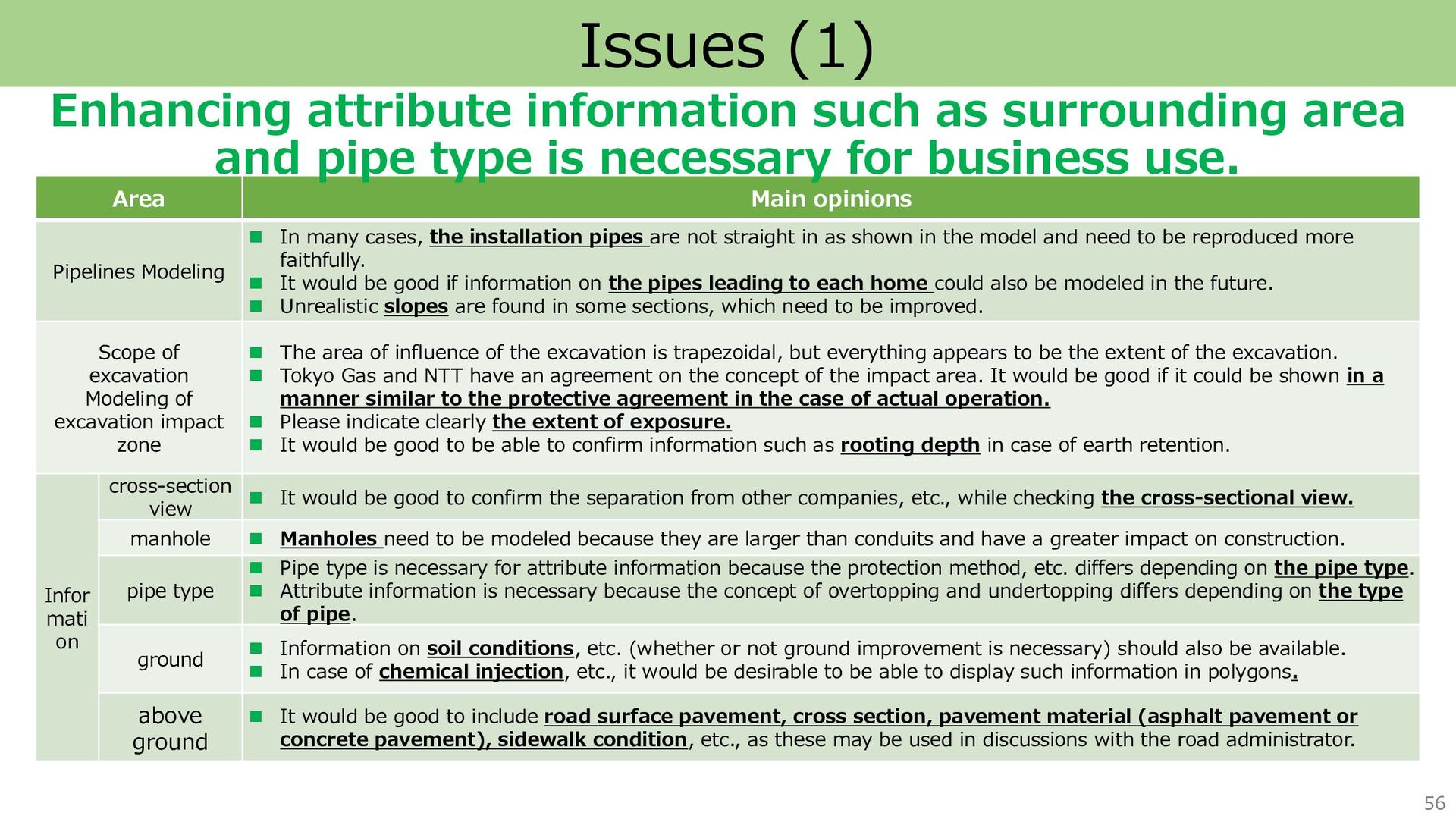
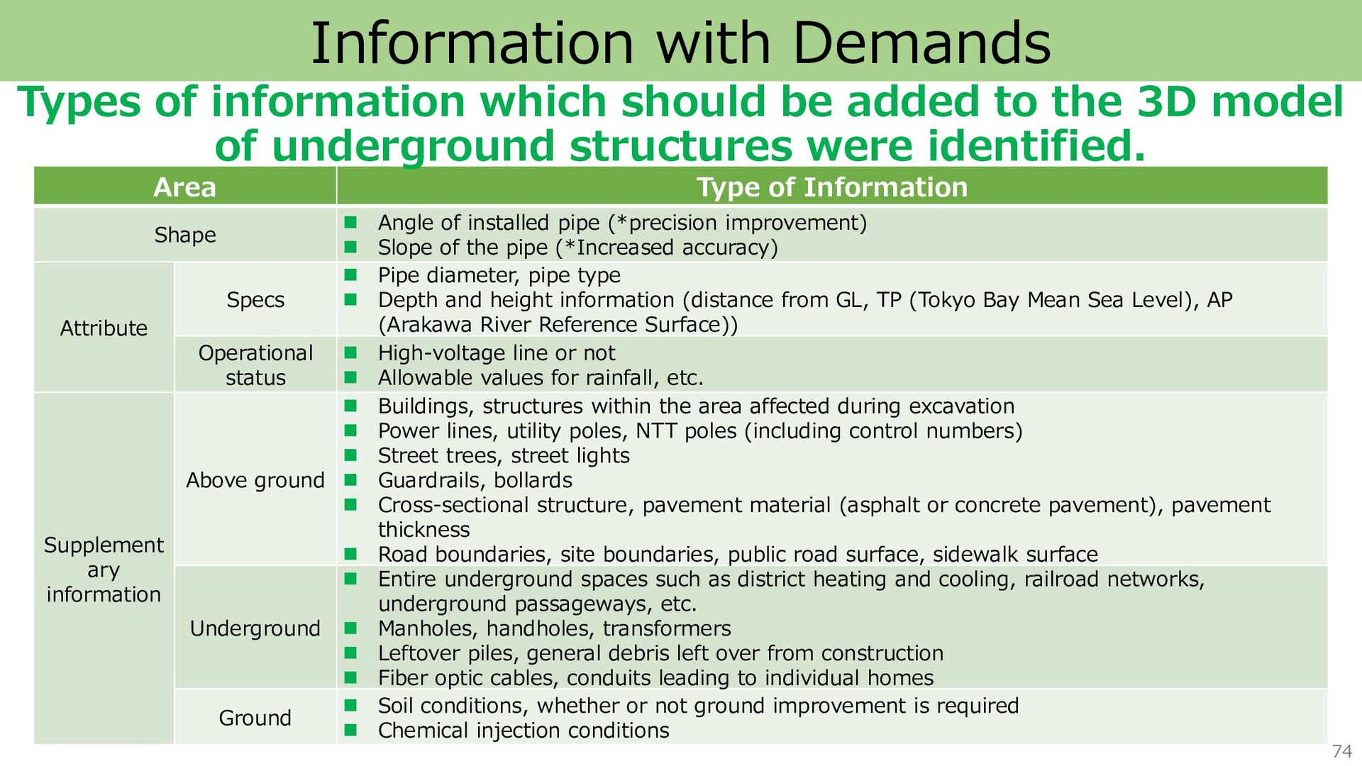
    Angle of installed pipe (*precision improvement) ◼ Slope of the pipe (*Increased accuracy) Attribute Specs ◼ Pipe diameter, pipe type ◼ Depth and height information (distance from GL, TP (Tokyo Bay Mean Sea Level), AP (Arakawa River Reference Surface)) Operational status ◼ High-voltage line or not ◼ Allowable values for rainfall, etc. Supplement ary information Above ground ◼ Buildings, structures within the area affected during excavation ◼ Power lines, utility poles, NTT poles (including control numbers) ◼ Street trees, street lights ◼ Guardrails, bollards ◼ Cross-sectional structure, pavement material (asphalt or concrete pavement), pavement thickness ◼ Road boundaries, site boundaries, public road surface, sidewalk surface Underground ◼ Entire underground spaces such as district heating and cooling, railroad networks, underground passageways, etc. ◼ Manholes, handholes, transformers ◼ Leftover piles, general debris left over from construction ◼ Fiber optic cables, conduits leading to individual homes Ground ◼ Soil conditions, whether or not ground improvement is required ◼ Chemical injection conditions Types of information which should be added to the 3D model of underground structures were identified.
  62. 75 Functions with Demands Process Function Plan Information gathering ◼

    Automatic application function ◼ Automatic determination function for presence of buried objects Design & Construction negotiation ◼ Input and display function of excavation area (in accordance with protection agreements with various organizations) ◼ Function for determining interference with other facilities, identifying the proximity position, and measuring the separation ◼ Listing function of management organizations of interfering facilities ◼ Display function of plan view and cross-sectional view ◼ Display function of exposed area ◼ Display function of rooting ◼ Display function of rooting depth of earth retaining walls, etc. ◼ 2D drawing creation function ◼ Ability to record the contents of negotiation and create documents Functions which should be added to the 3D model of underground structures were identified.
  63. Underground digital twin provides security and safety for Tokyo residents.

    77 Future Directions Operational issues Technical issues ◼ Unifying standards for data maintenance in the industry ◼ Exploring use cases that do not require strict accuracy and freshness (e.g., utilization at the planning stage) ◼ Acquisition and superimposition of data on buildings, road features, utility poles, and power lines, through the use of point cloud data. ◼Establishing continuous and efficient methods of obtaining subsurface information (use of LiDAR during construction, adoption of new subsurface measurement methods, etc.) ◼Establishment of a security-conscious environment that can be used only by relevant parties. ◼Sharing roles among related agencies and establishing sustainable operation system We will address technical and operational issues and promote the establishment of a sustainable mechanism.