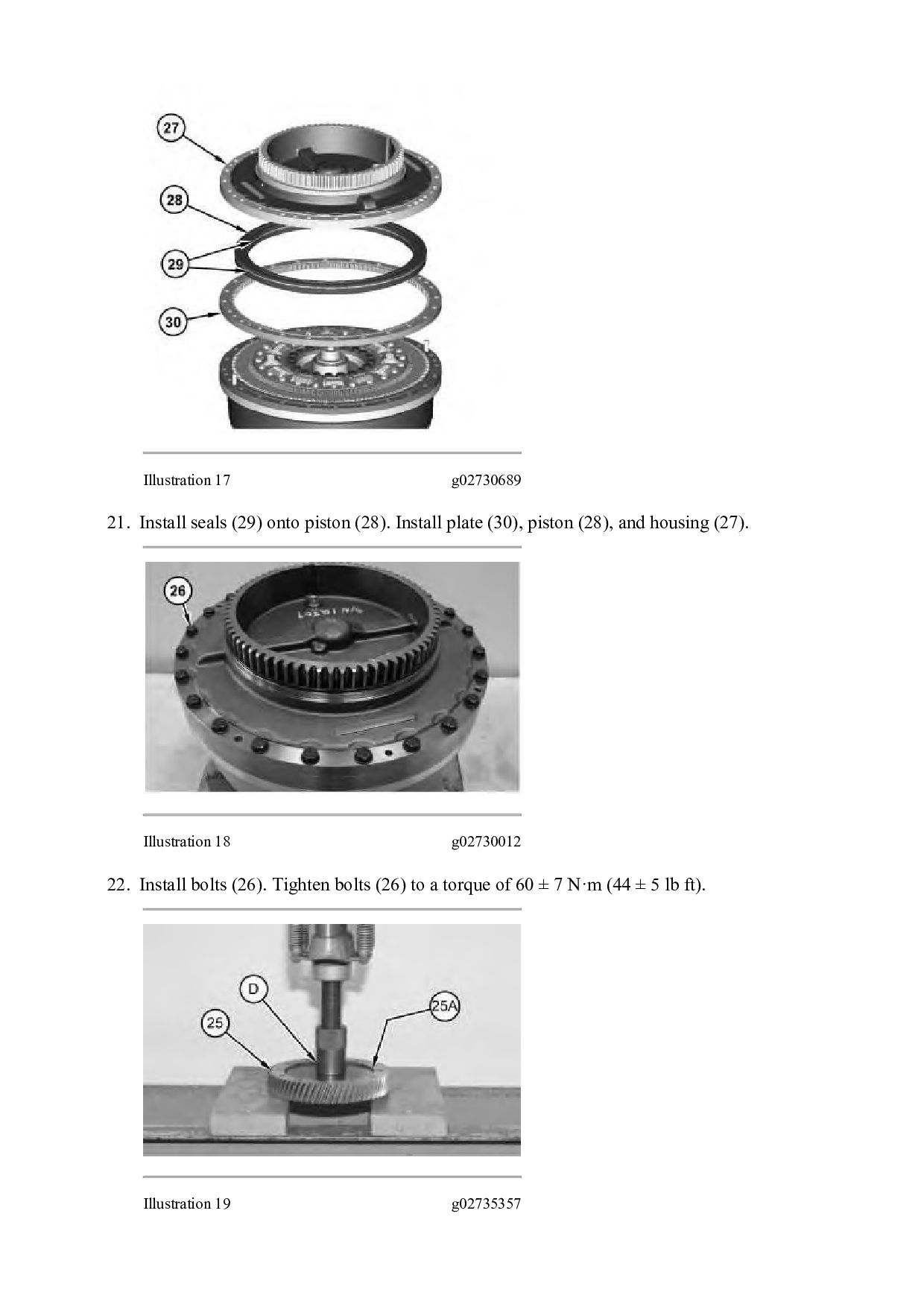
LOADER MK2 Configuration: 980M Wheel Loader MK200001-UP (MACHINE) POWERED BY C13 Engine Disassembly and Assembly 980M T4 and 982M T4 Wheel Loader Power Train Media Number -M0075587-02 Publication Date -01/08/2012 Date Updated -17/07/2018 i06838485 Torque Converter - Assemble - Lock Up Clutch with Freewheel Stator SMCS - 3101-016 Assembly Procedure Table 1 Required Tools Tool Part Number Part Description Qty A 439-3938 Link Bracket 3 G 8T-5096 Dial Indicator Test Group 1 5P-2390 Gauge Tool Group 1 H 1P-0520 Driver Group 1 J - Guide Stud (3/8 - 16 by 8 in) 2 K - Guide Stud (1/2 - 13 by 3 in) 3 L 2P-8312 Retaining Ring Pliers 1
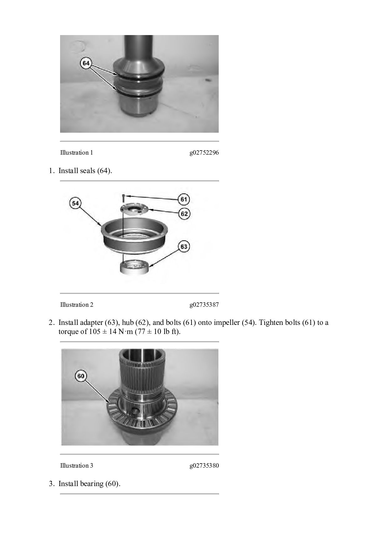
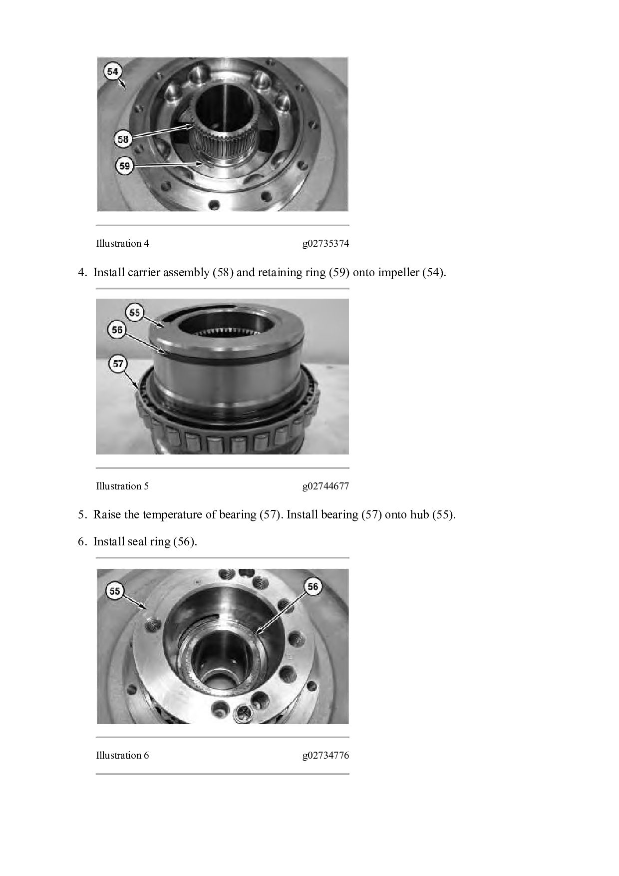
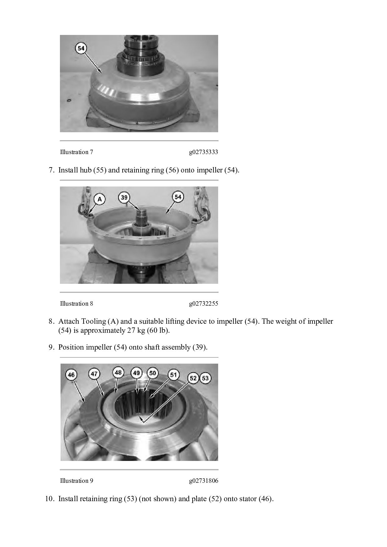
ring (59) onto impeller (54). Illustration 5 g02744677 5. Raise the temperature of bearing (57). Install bearing (57) onto hub (55). 6. Install seal ring (56). Illustration 6 g02734776
(56) onto impeller (54). Illustration 8 g02732255 8. Attach Tooling (A) and a suitable lifting device to impeller (54). The weight of impeller (54) is approximately 27 kg (60 lb). 9. Position impeller (54) onto shaft assembly (39). Illustration 9 g02731806 10. Install retaining ring (53) (not shown) and plate (52) onto stator (46).
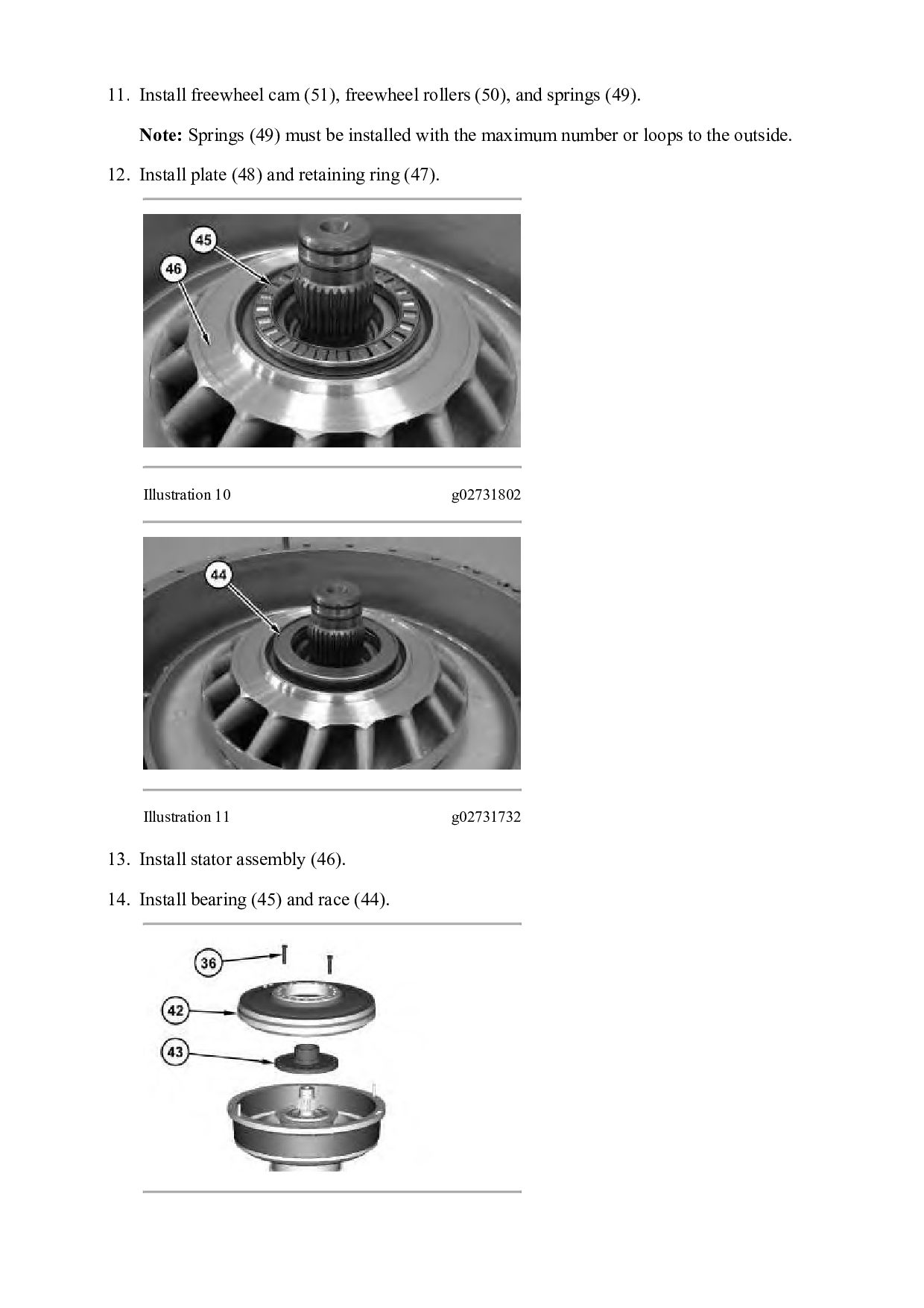
(49). Note: Springs (49) must be installed with the maximum number or loops to the outside. 12. Install plate (48) and retaining ring (47). Illustration 10 g02731802 Illustration 11 g02731732 13. Install stator assembly (46). 14. Install bearing (45) and race (44).
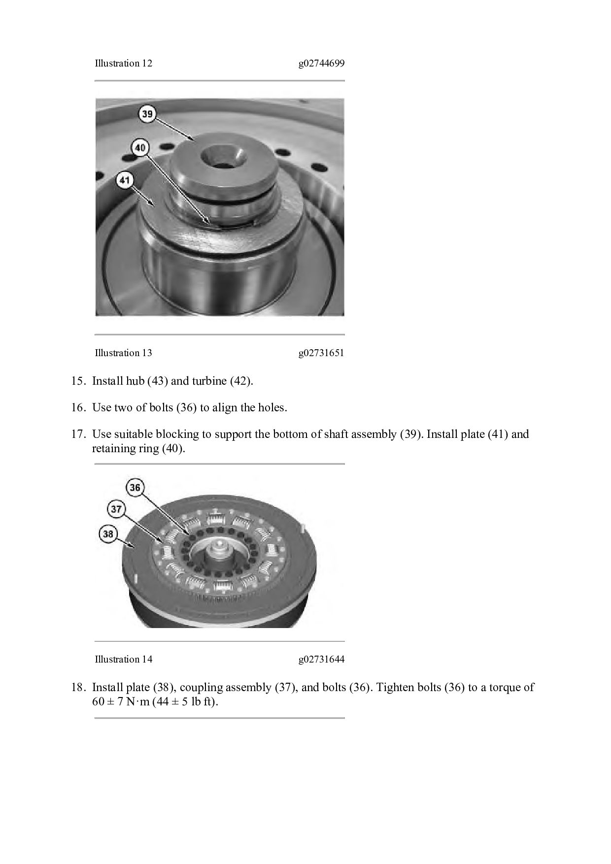
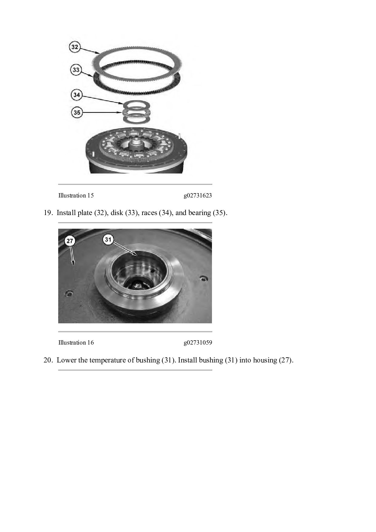
and turbine (42). 16. Use two of bolts (36) to align the holes. 17. Use suitable blocking to support the bottom of shaft assembly (39). Install plate (41) and retaining ring (40). Illustration 14 g02731644 18. Install plate (38), coupling assembly (37), and bolts (36). Tighten bolts (36) to a torque of 60 ± 7 N·m (44 ± 5 lb ft).
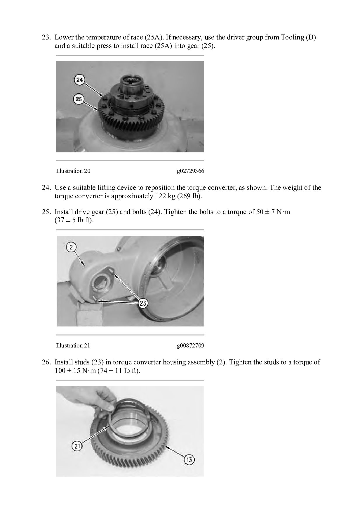
the driver group from Tooling (D) and a suitable press to install race (25A) into gear (25). Illustration 20 g02729366 24. Use a suitable lifting device to reposition the torque converter, as shown. The weight of the torque converter is approximately 122 kg (269 lb). 25. Install drive gear (25) and bolts (24). Tighten the bolts to a torque of 50 ± 7 N·m (37 ± 5 lb ft). Illustration 21 g00872709 26. Install studs (23) in torque converter housing assembly (2). Tighten the studs to a torque of 100 ± 15 N·m (74 ± 11 lb ft).
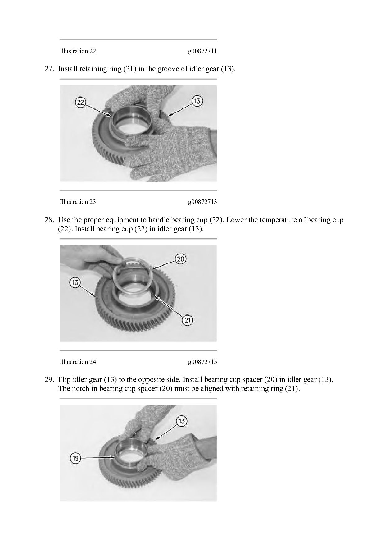
groove of idler gear (13). Illustration 23 g00872713 28. Use the proper equipment to handle bearing cup (22). Lower the temperature of bearing cup (22). Install bearing cup (22) in idler gear (13). Illustration 24 g00872715 29. Flip idler gear (13) to the opposite side. Install bearing cup spacer (20) in idler gear (13). The notch in bearing cup spacer (20) must be aligned with retaining ring (21).
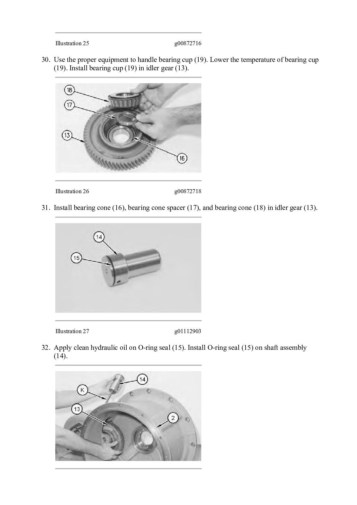
bearing cup (19). Lower the temperature of bearing cup (19). Install bearing cup (19) in idler gear (13). Illustration 26 g00872718 31. Install bearing cone (16), bearing cone spacer (17), and bearing cone (18) in idler gear (13). Illustration 27 g01112903 32. Apply clean hydraulic oil on O-ring seal (15). Install O-ring seal (15) on shaft assembly (14).
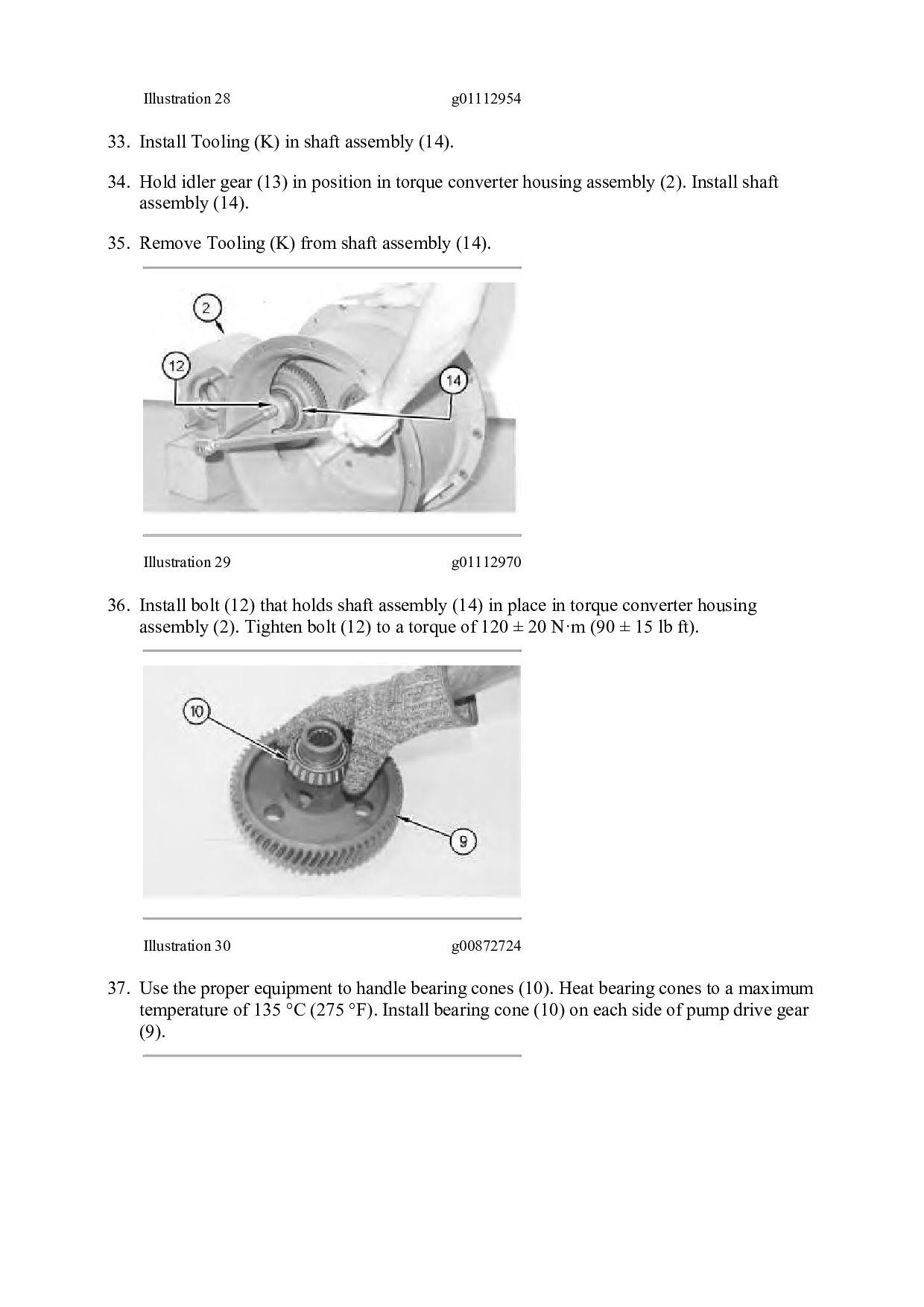
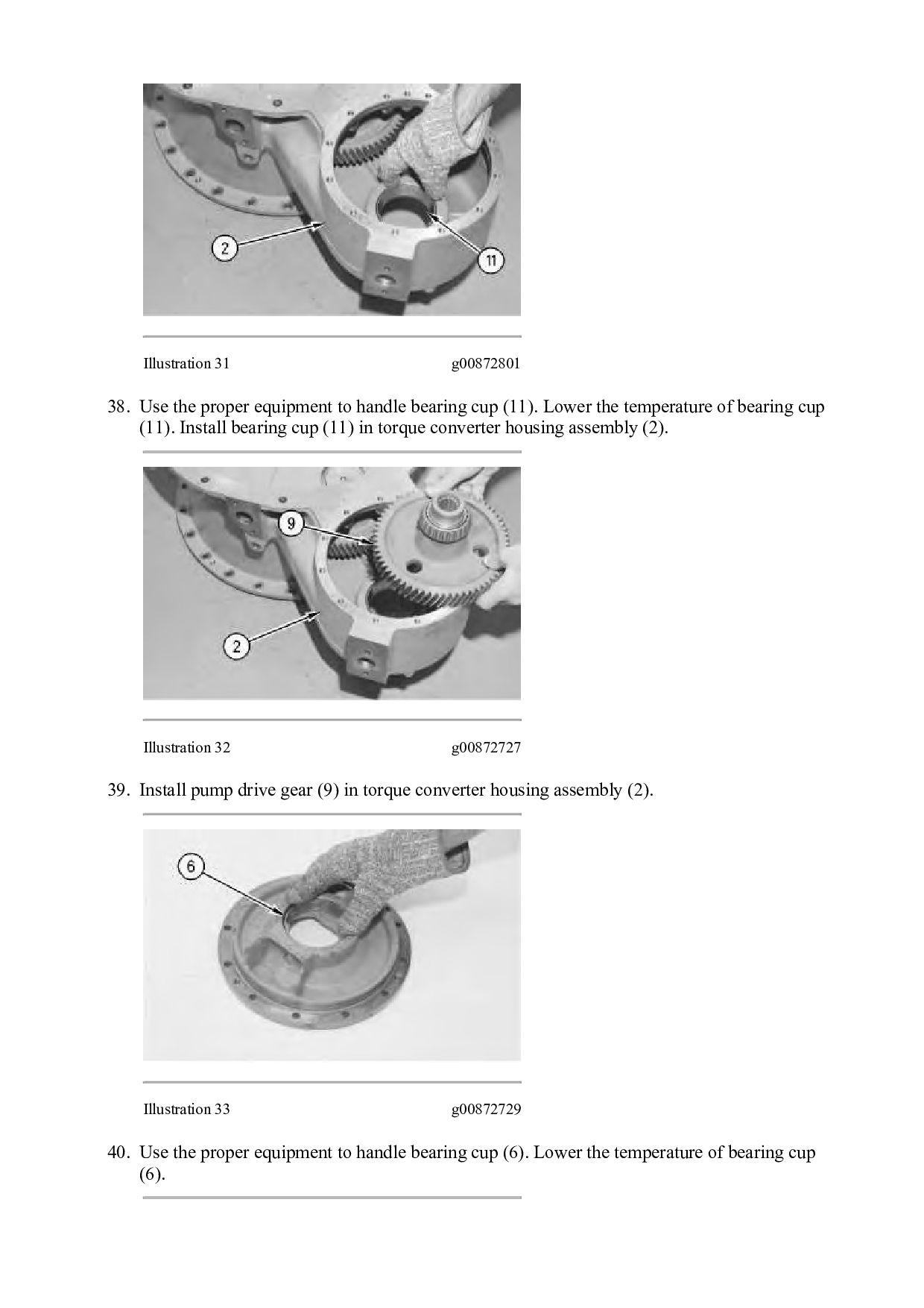
(14). 34. Hold idler gear (13) in position in torque converter housing assembly (2). Install shaft assembly (14). 35. Remove Tooling (K) from shaft assembly (14). Illustration 29 g01112970 36. Install bolt (12) that holds shaft assembly (14) in place in torque converter housing assembly (2). Tighten bolt (12) to a torque of 120 ± 20 N·m (90 ± 15 lb ft). Illustration 30 g00872724 37. Use the proper equipment to handle bearing cones (10). Heat bearing cones to a maximum temperature of 135 °C (275 °F). Install bearing cone (10) on each side of pump drive gear (9).
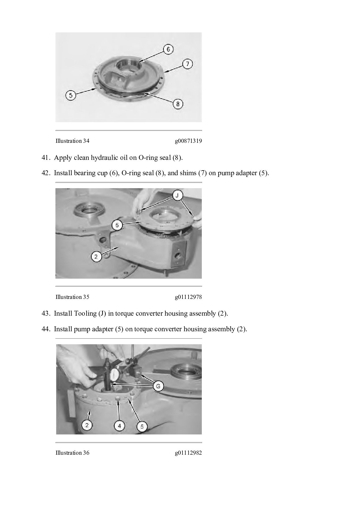
bearing cup (11). Lower the temperature of bearing cup (11). Install bearing cup (11) in torque converter housing assembly (2). Illustration 32 g00872727 39. Install pump drive gear (9) in torque converter housing assembly (2). Illustration 33 g00872729 40. Use the proper equipment to handle bearing cup (6). Lower the temperature of bearing cup (6).
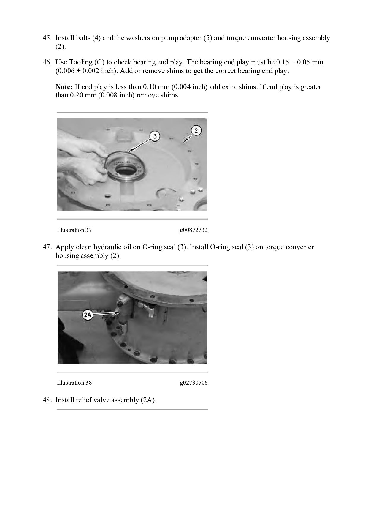
(5) and torque converter housing assembly (2). 46. Use Tooling (G) to check bearing end play. The bearing end play must be 0.15 ± 0.05 mm (0.006 ± 0.002 inch). Add or remove shims to get the correct bearing end play. Note: If end play is less than 0.10 mm (0.004 inch) add extra shims. If end play is greater than 0.20 mm (0.008 inch) remove shims. Illustration 37 g00872732 47. Apply clean hydraulic oil on O-ring seal (3). Install O-ring seal (3) on torque converter housing assembly (2). Illustration 38 g02730506 48. Install relief valve assembly (2A).
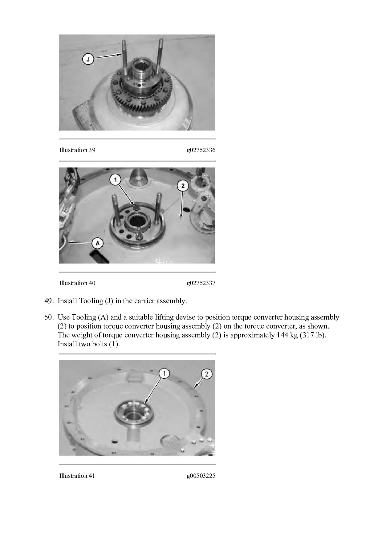
in the carrier assembly. 50. Use Tooling (A) and a suitable lifting devise to position torque converter housing assembly (2) to position torque converter housing assembly (2) on the torque converter, as shown. The weight of torque converter housing assembly (2) is approximately 144 kg (317 lb). Install two bolts (1). Illustration 41 g00503225
(2). Tighten bolts (1) to a torque of 120 ± 20 N·m (90 ± 15 lb ft). End By: a. Connect the torque converter to the transmission and to the output transfer gears. Copyright 1993 - 2021 Caterpillar Inc. All Rights Reserved. Private Network For SIS Licensees. Tue Mar 16 11:29:10 UTC+0800 2021
LOADER MK2 Configuration: 980M Wheel Loader MK200001-UP (MACHINE) POWERED BY C13 Engine Disassembly and Assembly 980M T4 and 982M T4 Wheel Loader Power Train Media Number -M0075587-02 Publication Date -01/08/2012 Date Updated -17/07/2018 i06838249 Transmission from Output Transfer Gears - Separate SMCS - 3002-076 Separation Procedure Table 1 Required Tools Tool Part Number Part Description Qty A 1U-9200 Lever Puller Hoist 1 B 439-3940 Link Bracket 1 C 395-1094 Link Bracket 3 D 1P-2420 Transmission Repair Stand 1 Start By: a. Separate the torque converter from the transmission.
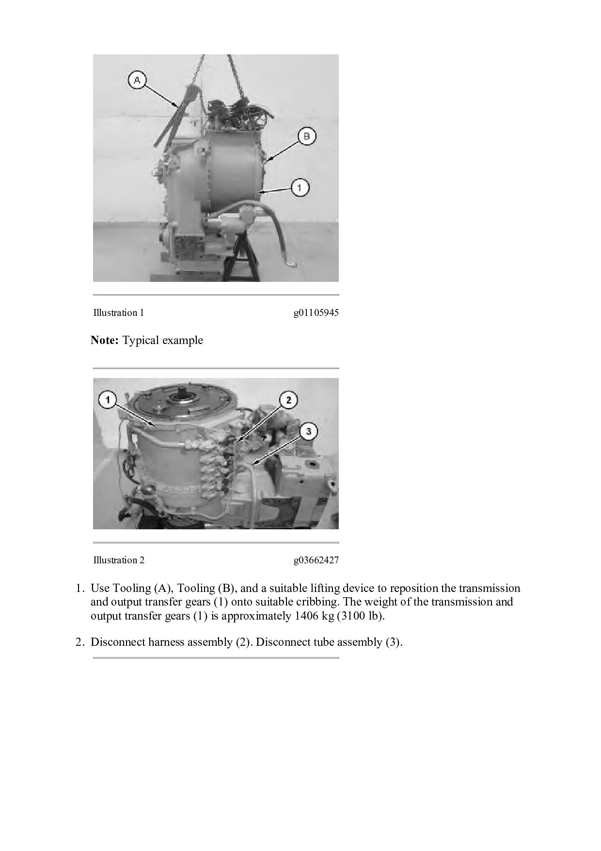
Use Tooling (A), Tooling (B), and a suitable lifting device to reposition the transmission and output transfer gears (1) onto suitable cribbing. The weight of the transmission and output transfer gears (1) is approximately 1406 kg (3100 lb). 2. Disconnect harness assembly (2). Disconnect tube assembly (3).
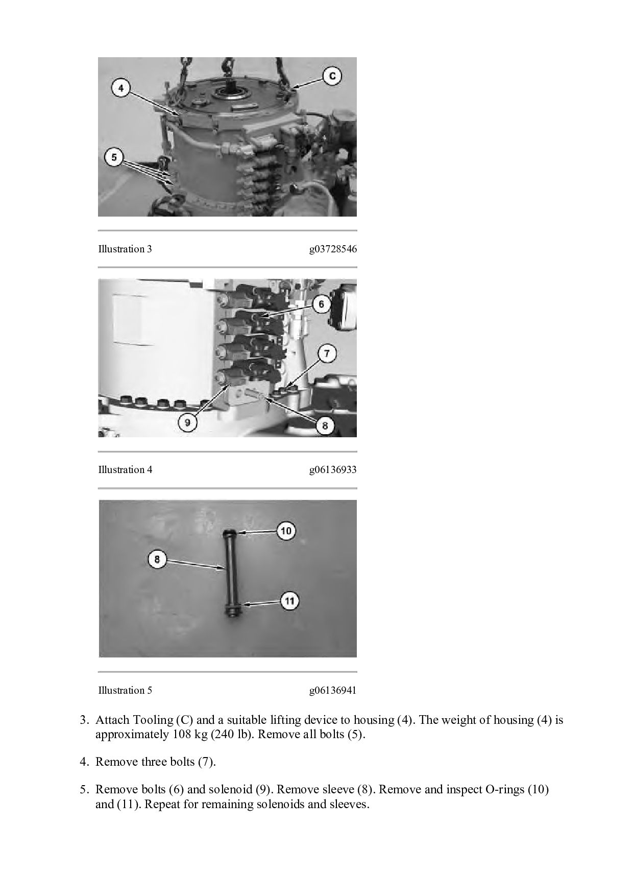
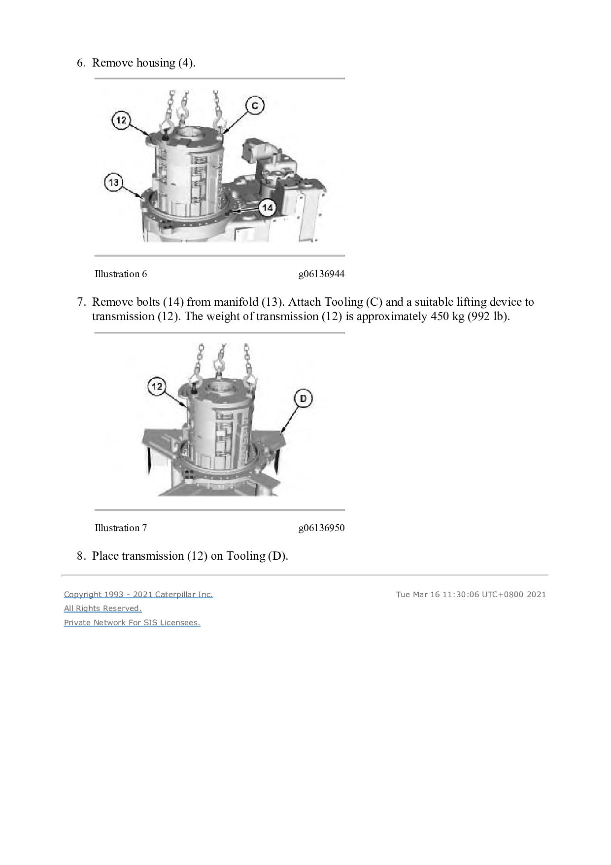
Attach Tooling (C) and a suitable lifting device to housing (4). The weight of housing (4) is approximately 108 kg (240 lb). Remove all bolts (5). 4. Remove three bolts (7). 5. Remove bolts (6) and solenoid (9). Remove sleeve (8). Remove and inspect O-rings (10) and (11). Repeat for remaining solenoids and sleeves.
(14) from manifold (13). Attach Tooling (C) and a suitable lifting device to transmission (12). The weight of transmission (12) is approximately 450 kg (992 lb). Illustration 7 g06136950 8. Place transmission (12) on Tooling (D). Copyright 1993 - 2021 Caterpillar Inc. All Rights Reserved. Private Network For SIS Licensees. Tue Mar 16 11:30:06 UTC+0800 2021
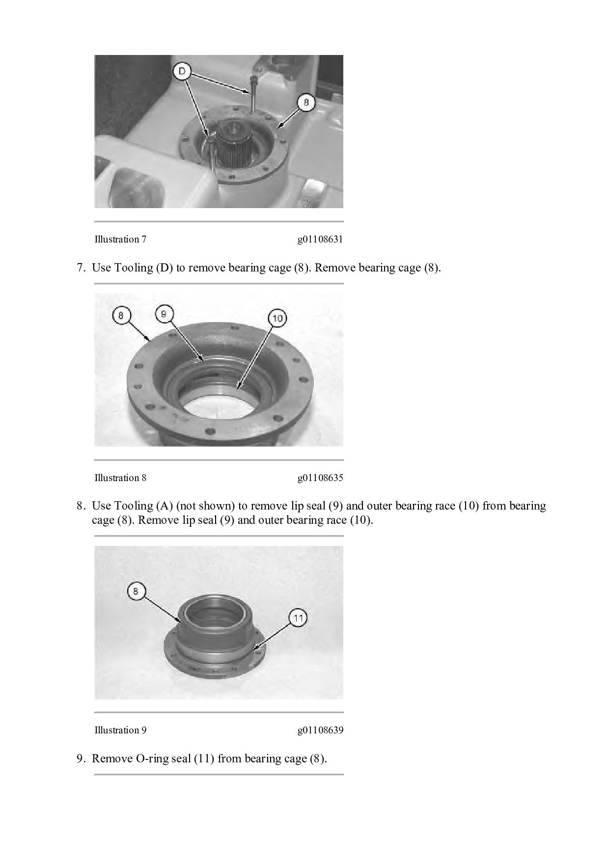
LOADER MK2 Configuration: 980M Wheel Loader MK200001-UP (MACHINE) POWERED BY C13 Engine Disassembly and Assembly 980M T4 and 982M T4 Wheel Loader Power Train Media Number -M0075587-02 Publication Date -01/08/2012 Date Updated -17/07/2018 i06839284 Output Transfer Gears - Disassemble SMCS - 3075-015-OJ Disassembly Procedure Table 1 Required Tools Tool Part Number Part Description Qty A 1P-0520 Driver Group 1 B 8B-7548 Push-puller 1 8B-7551 Bearing Puller Assembly 1 9S-9154 Step Plate 1 C 439-3940 Link Bracket 2 D 6L-7283 Bolt 2 Start By: a. Remove the transmission from the output transfer gears.
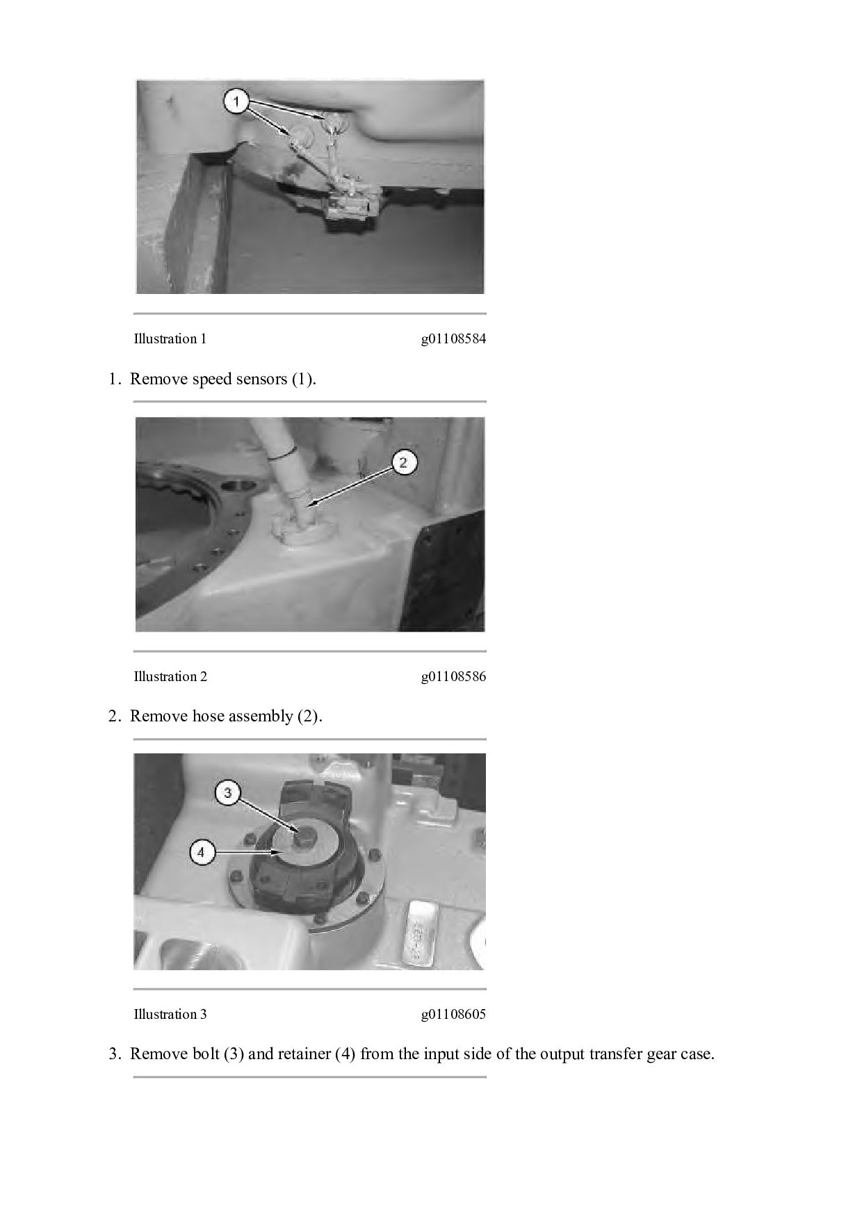
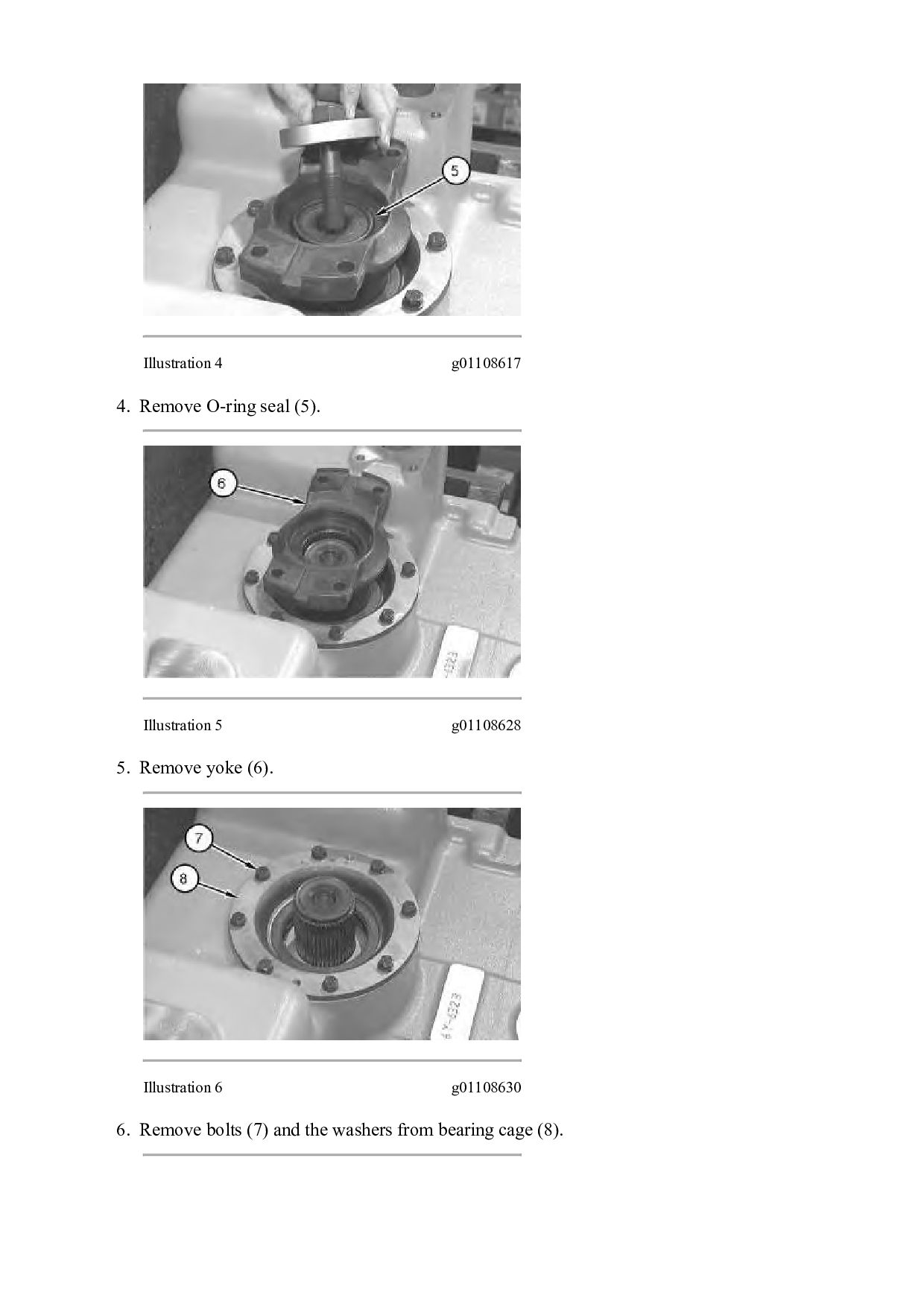
g01108586 2. Remove hose assembly (2). Illustration 3 g01108605 3. Remove bolt (3) and retainer (4) from the input side of the output transfer gear case.
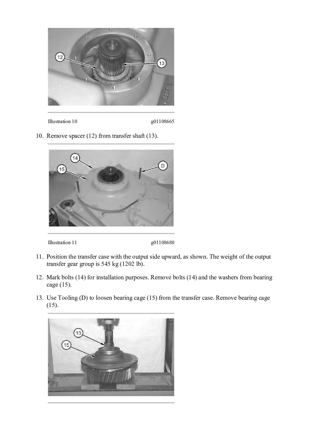
(13). Illustration 11 g01108680 11. Position the transfer case with the output side upward, as shown. The weight of the output transfer gear group is 545 kg (1202 lb). 12. Mark bolts (14) for installation purposes. Remove bolts (14) and the washers from bearing cage (15). 13. Use Tooling (D) to loosen bearing cage (15) from the transfer case. Remove bearing cage (15).
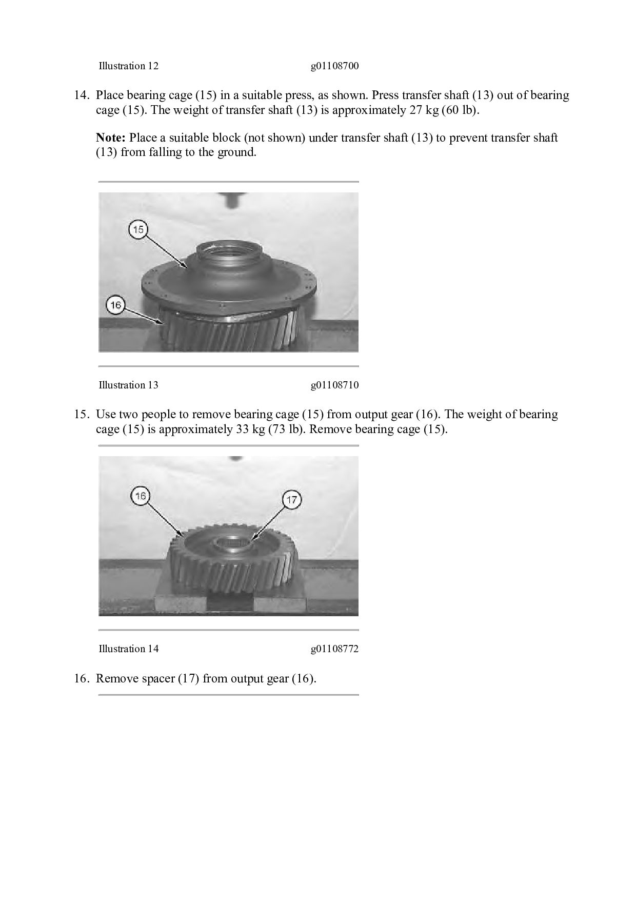
suitable press, as shown. Press transfer shaft (13) out of bearing cage (15). The weight of transfer shaft (13) is approximately 27 kg (60 lb). Note: Place a suitable block (not shown) under transfer shaft (13) to prevent transfer shaft (13) from falling to the ground. Illustration 13 g01108710 15. Use two people to remove bearing cage (15) from output gear (16). The weight of bearing cage (15) is approximately 33 kg (73 lb). Remove bearing cage (15). Illustration 14 g01108772 16. Remove spacer (17) from output gear (16).
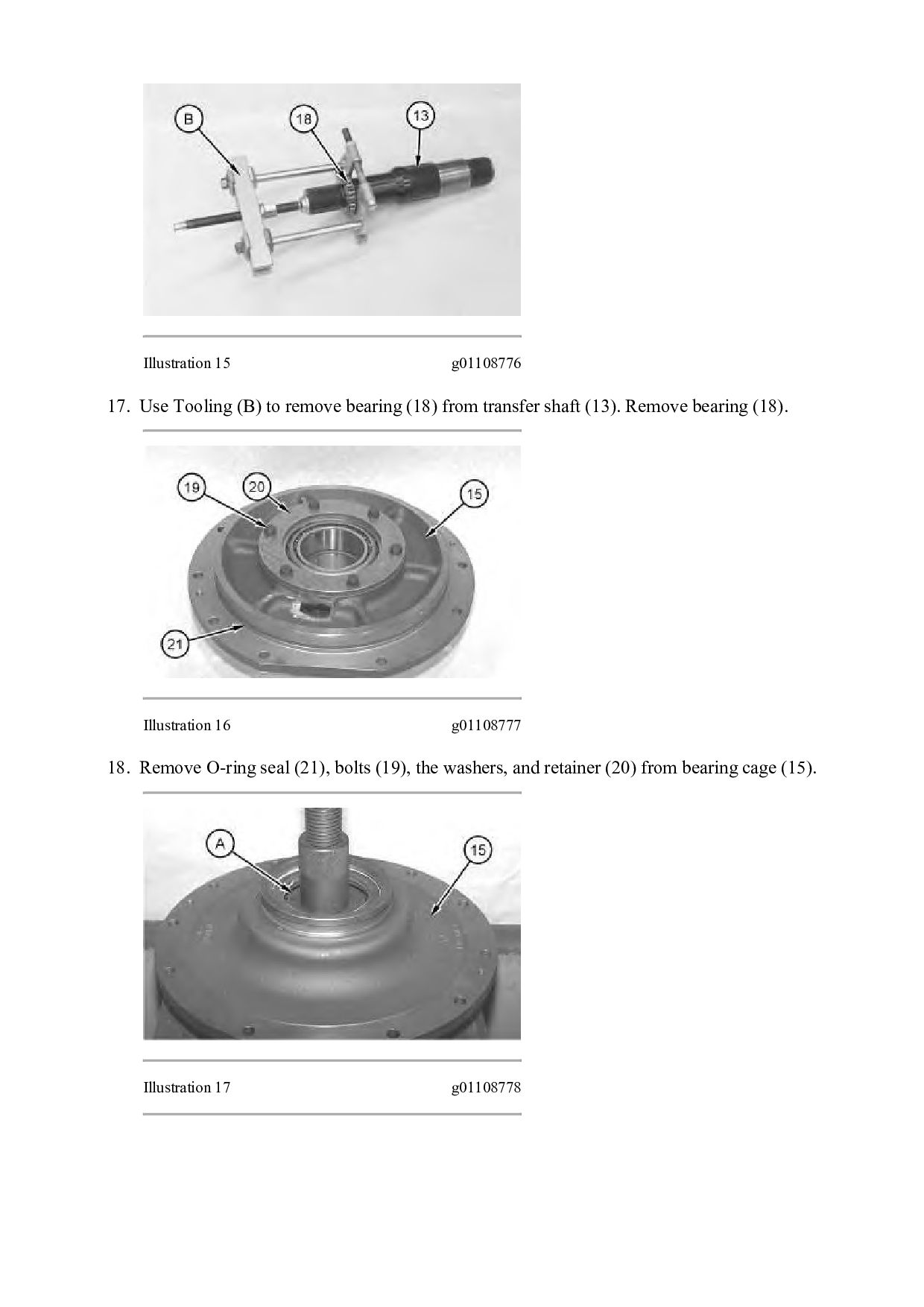
(18) from transfer shaft (13). Remove bearing (18). Illustration 16 g01108777 18. Remove O-ring seal (21), bolts (19), the washers, and retainer (20) from bearing cage (15). Illustration 17 g01108778
Then Get COMPLETE MANUAL. NO WAITING NOTE: If there is no response to click on the link above, please download the PDF document first and then click on it.
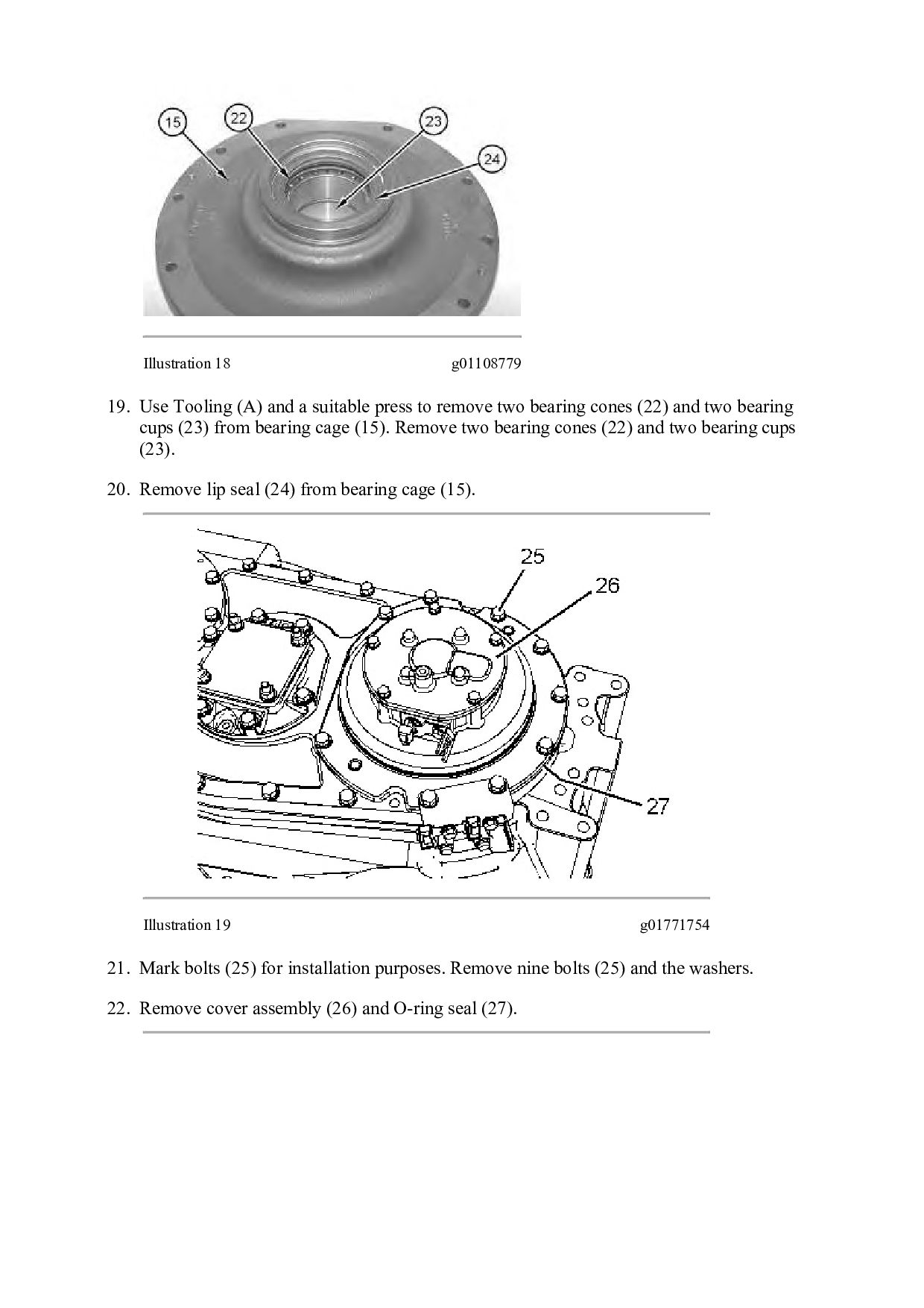
press to remove two bearing cones (22) and two bearing cups (23) from bearing cage (15). Remove two bearing cones (22) and two bearing cups (23). 20. Remove lip seal (24) from bearing cage (15). Illustration 19 g01771754 21. Mark bolts (25) for installation purposes. Remove nine bolts (25) and the washers. 22. Remove cover assembly (26) and O-ring seal (27).

 Your Podcast. Everywhere. Effortlessly.


 dcrfdycnvk
 apolaine
 mongodb
 marcoroth
 aleyda
 eileencodes
 honzajavorek
 rasagy
 paigeccino
 gurzu
 brad_frost
 ks91
 elsirapls