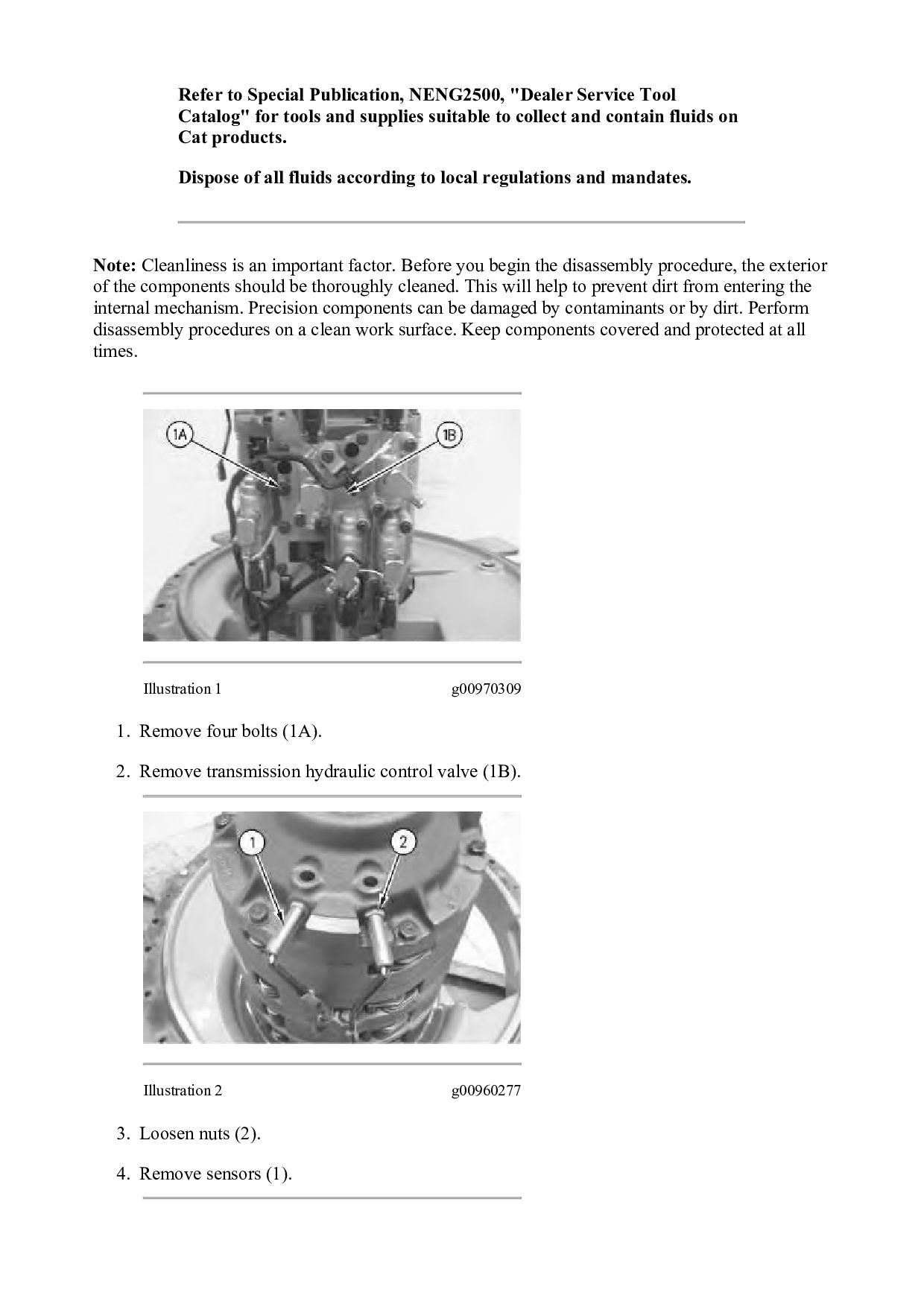
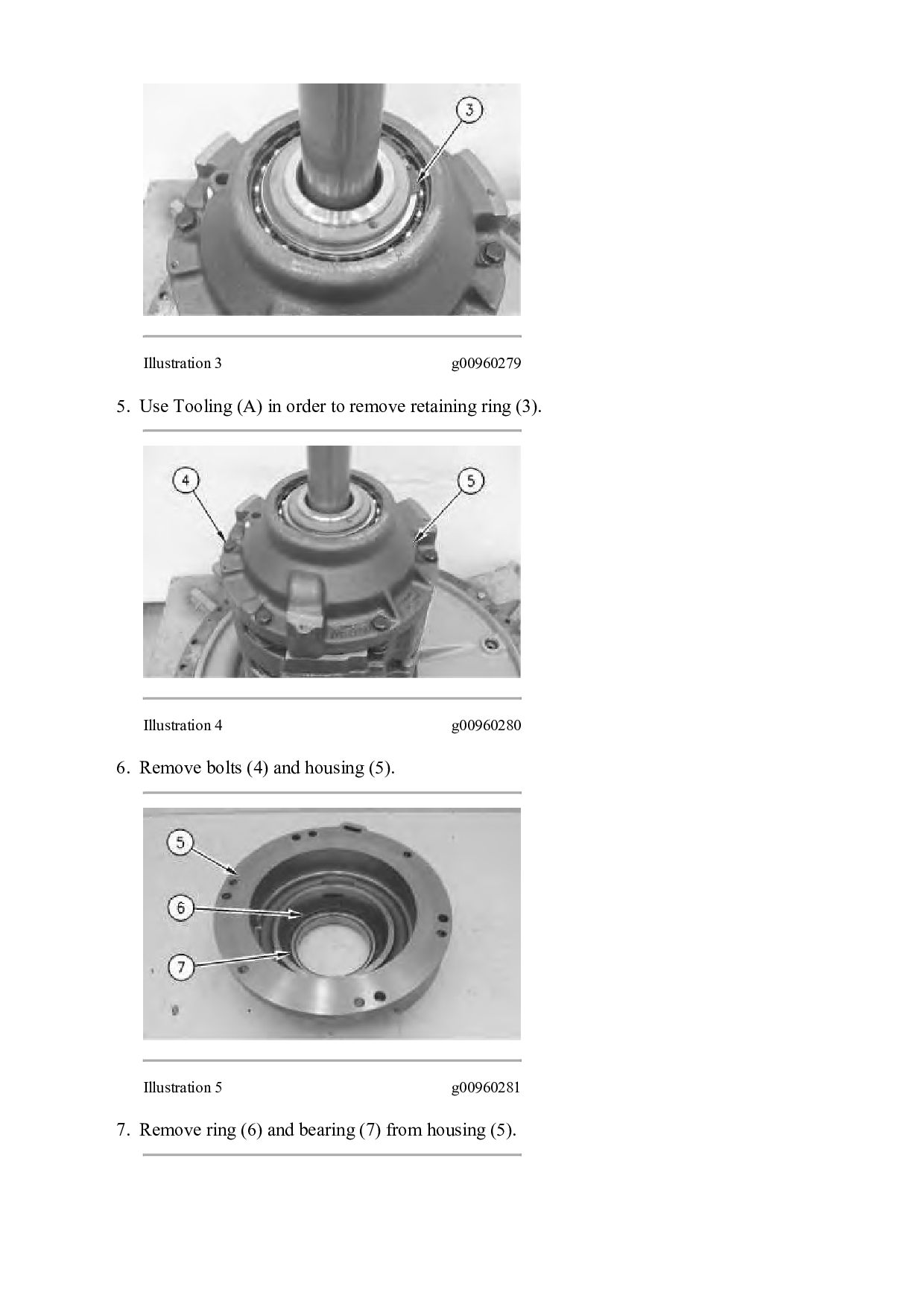
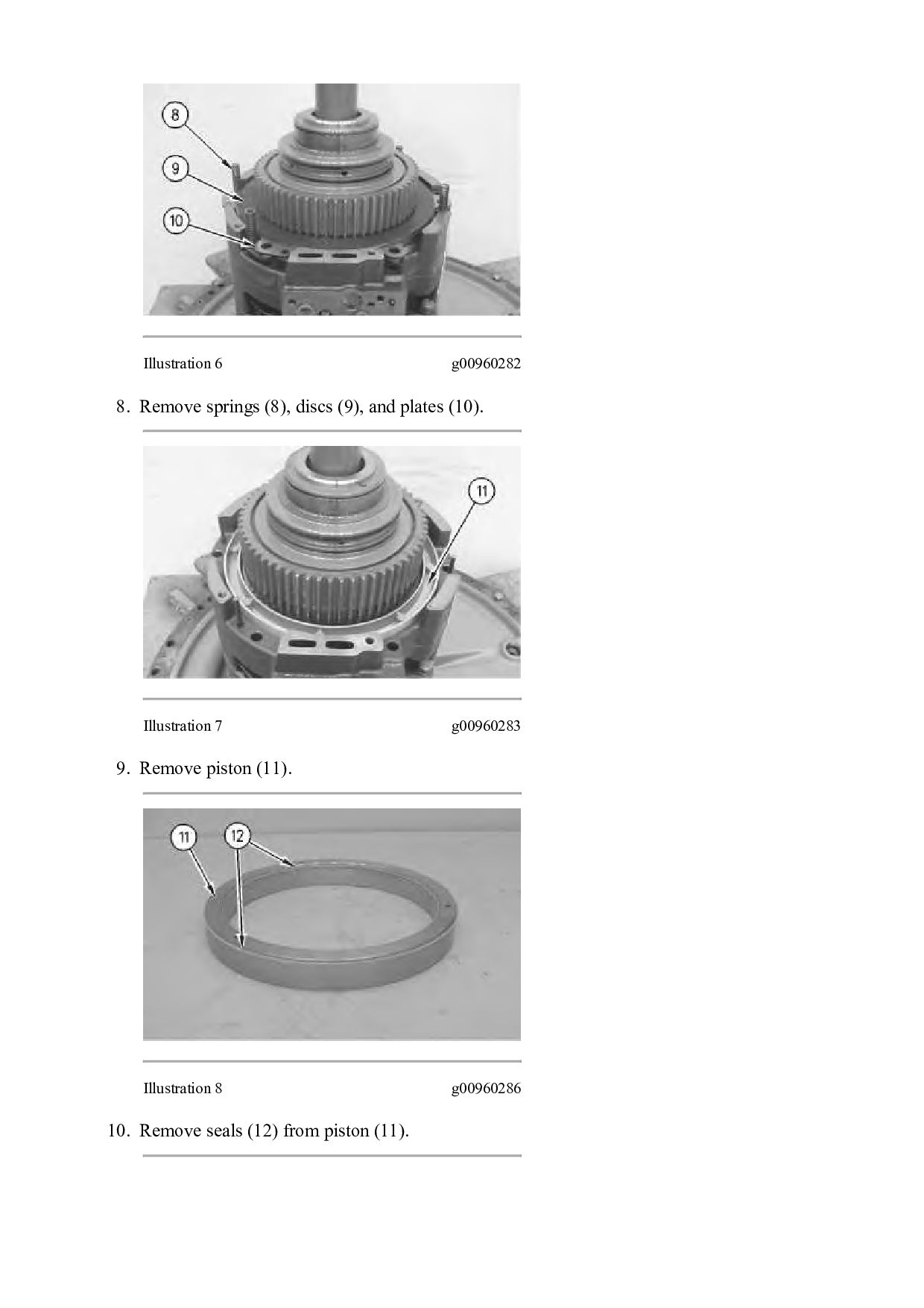
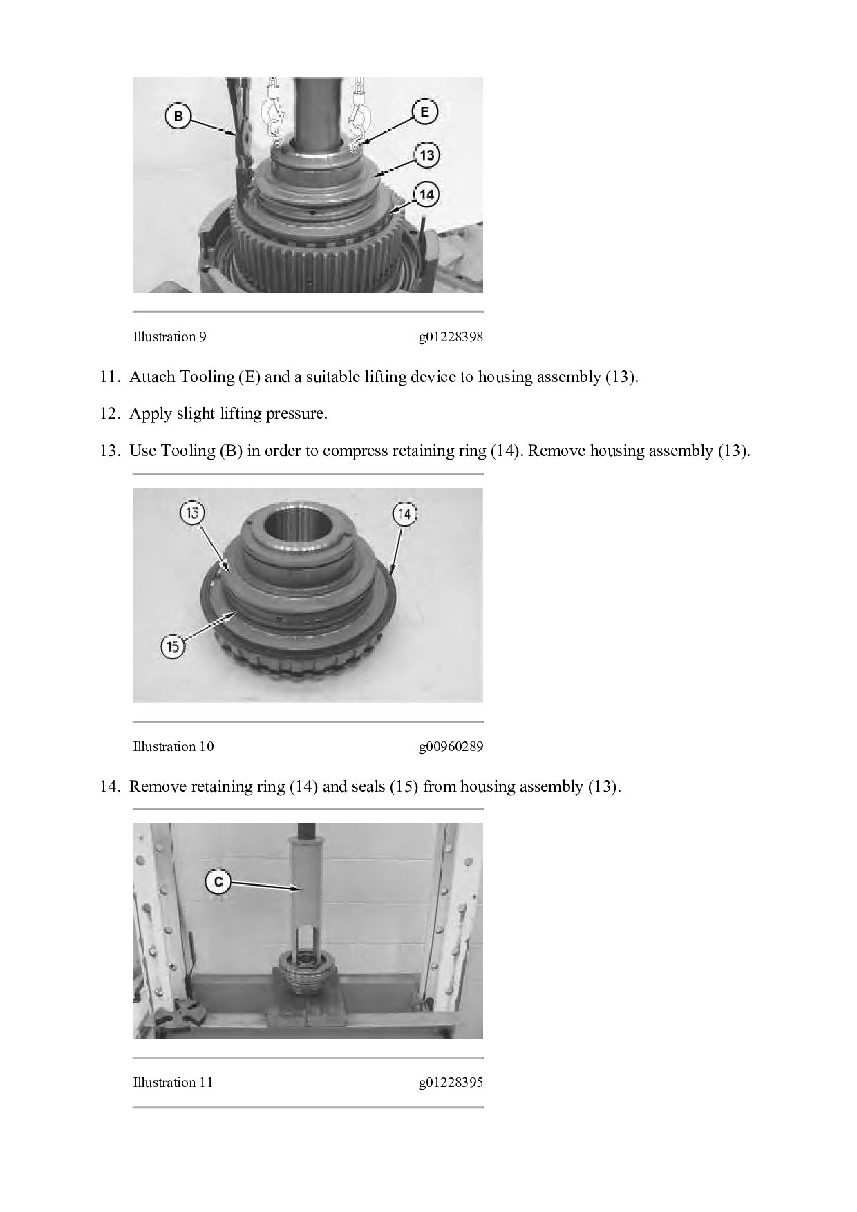
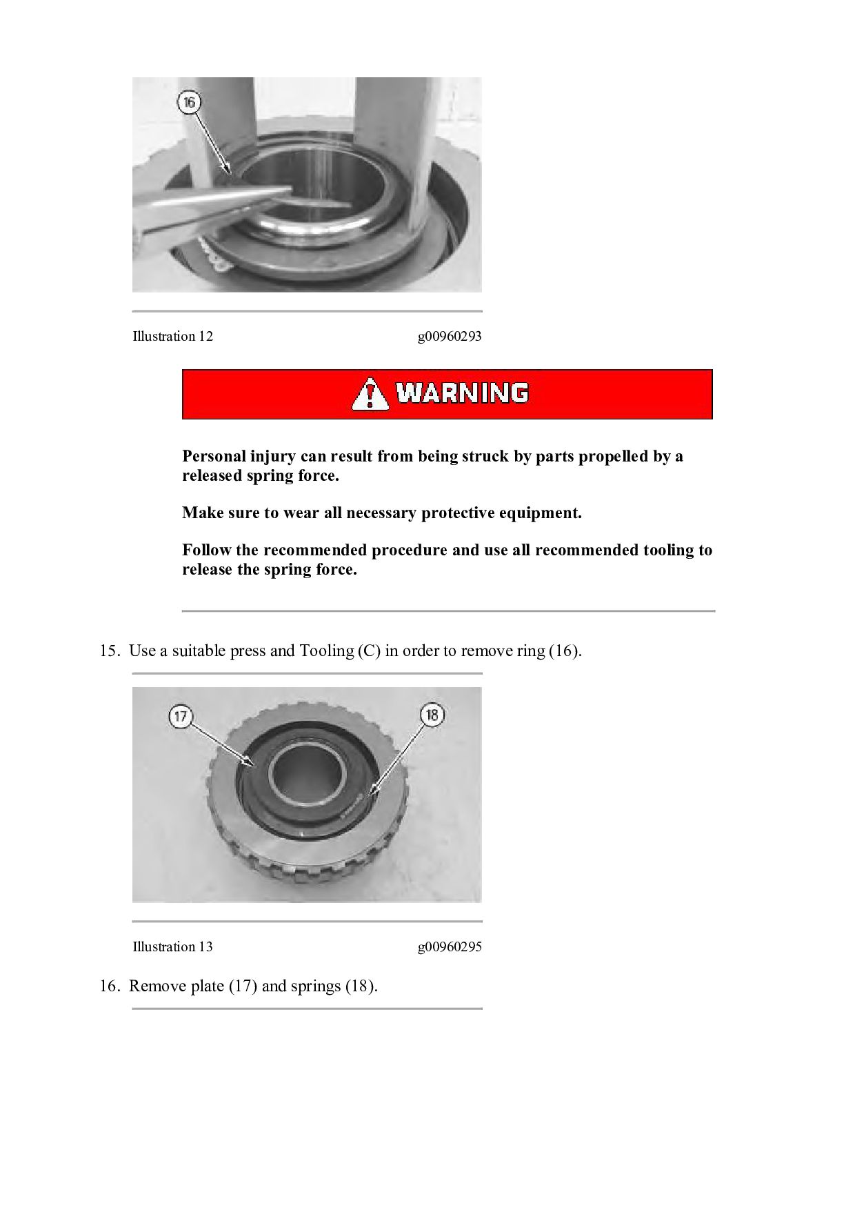
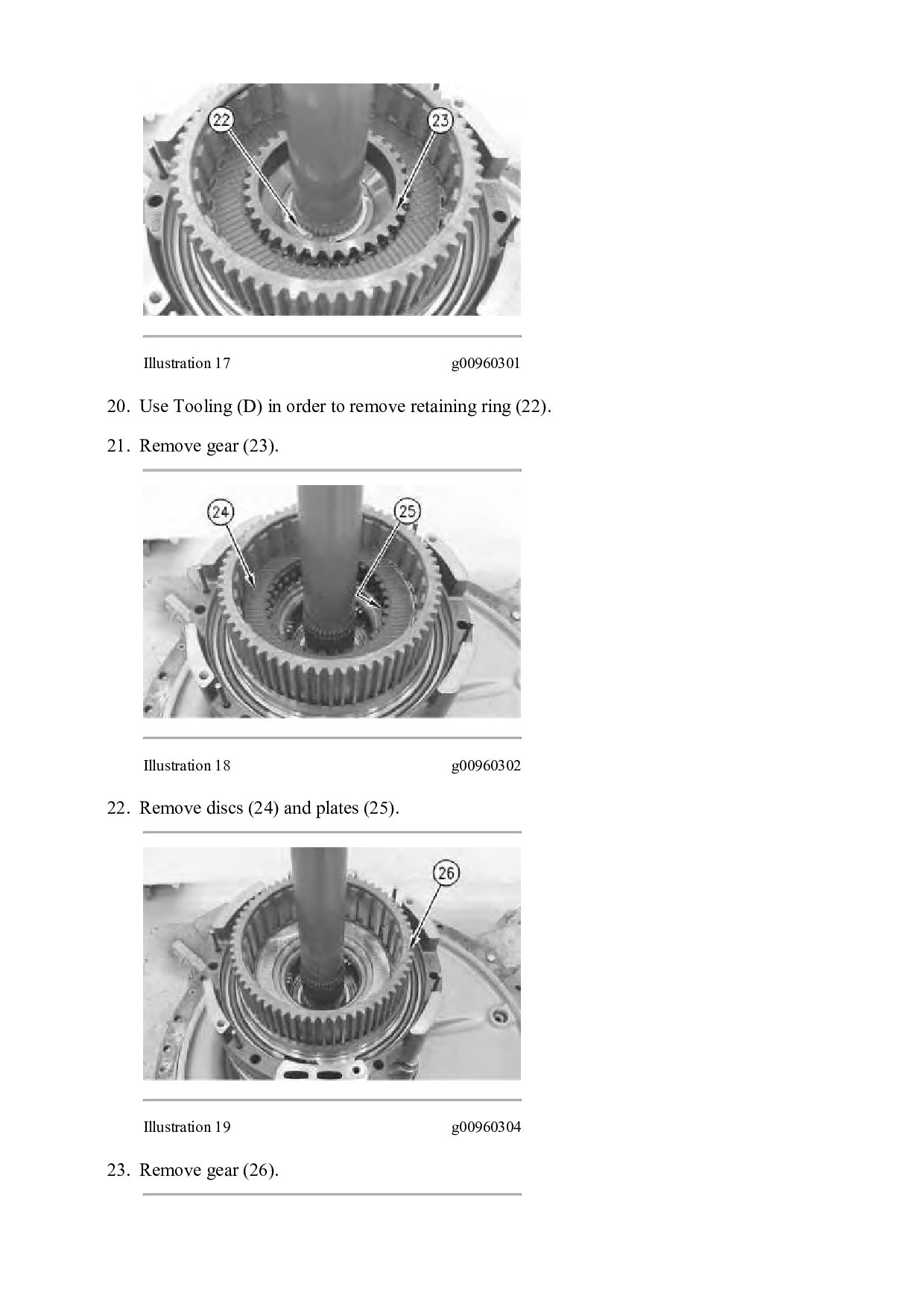
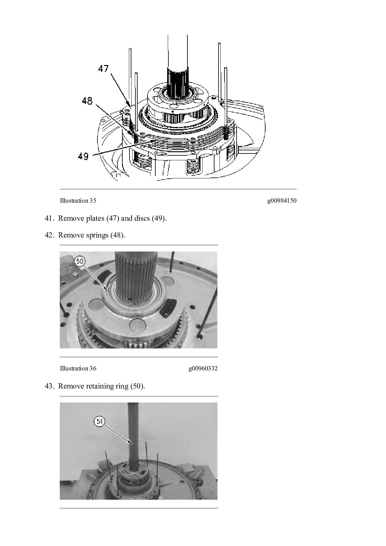
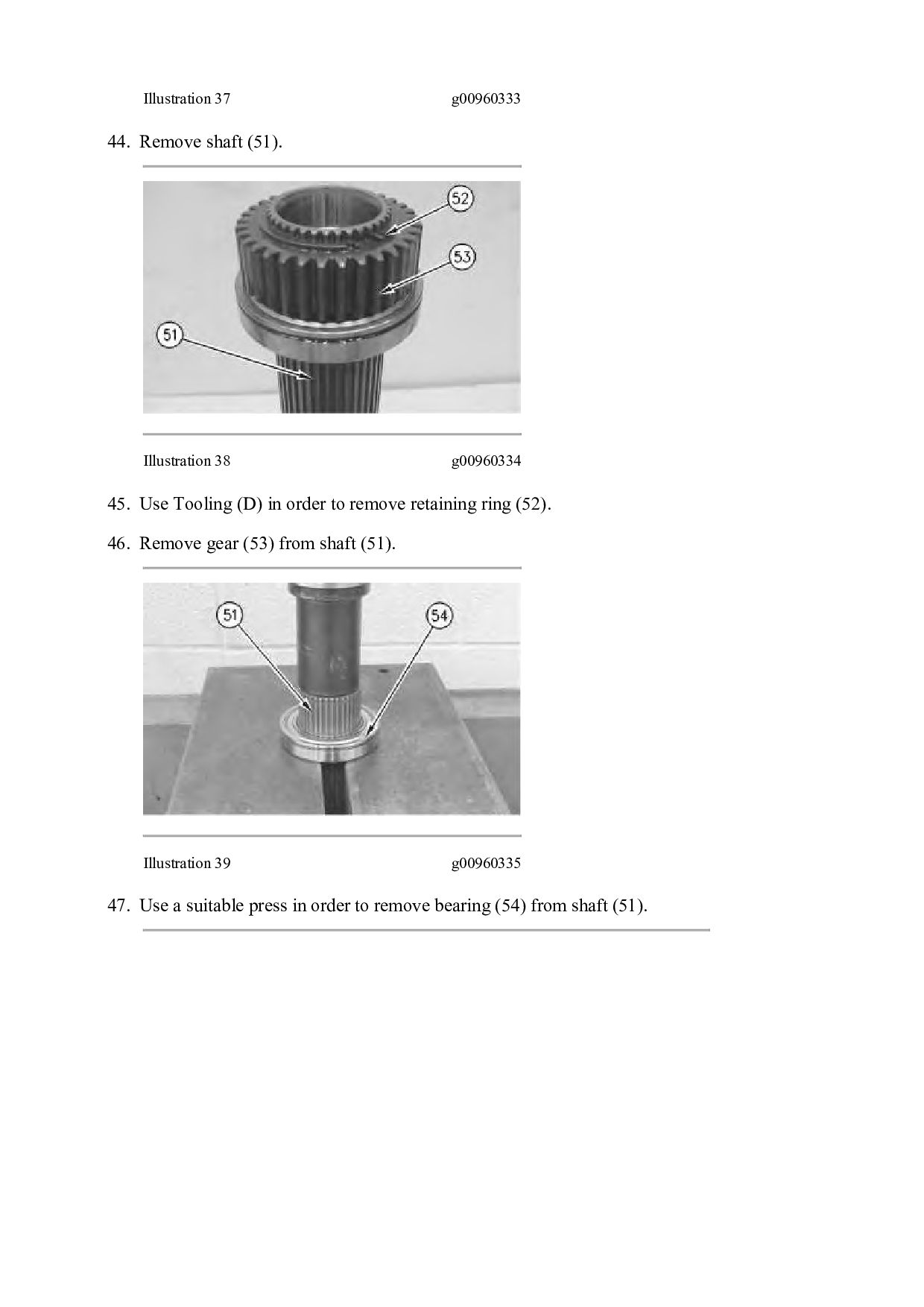
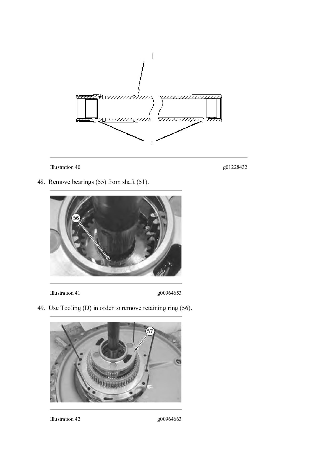
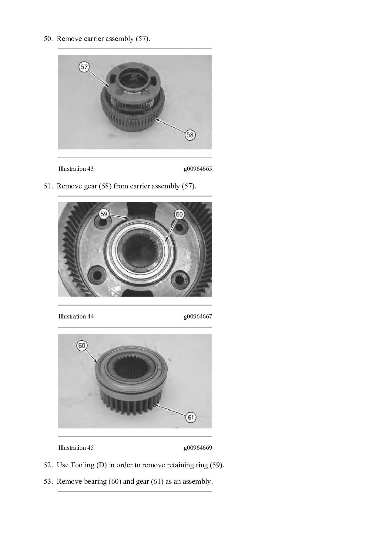
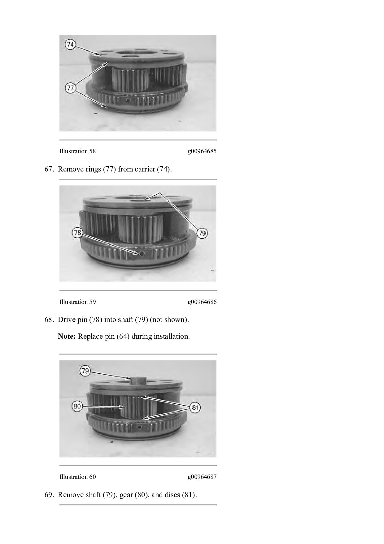
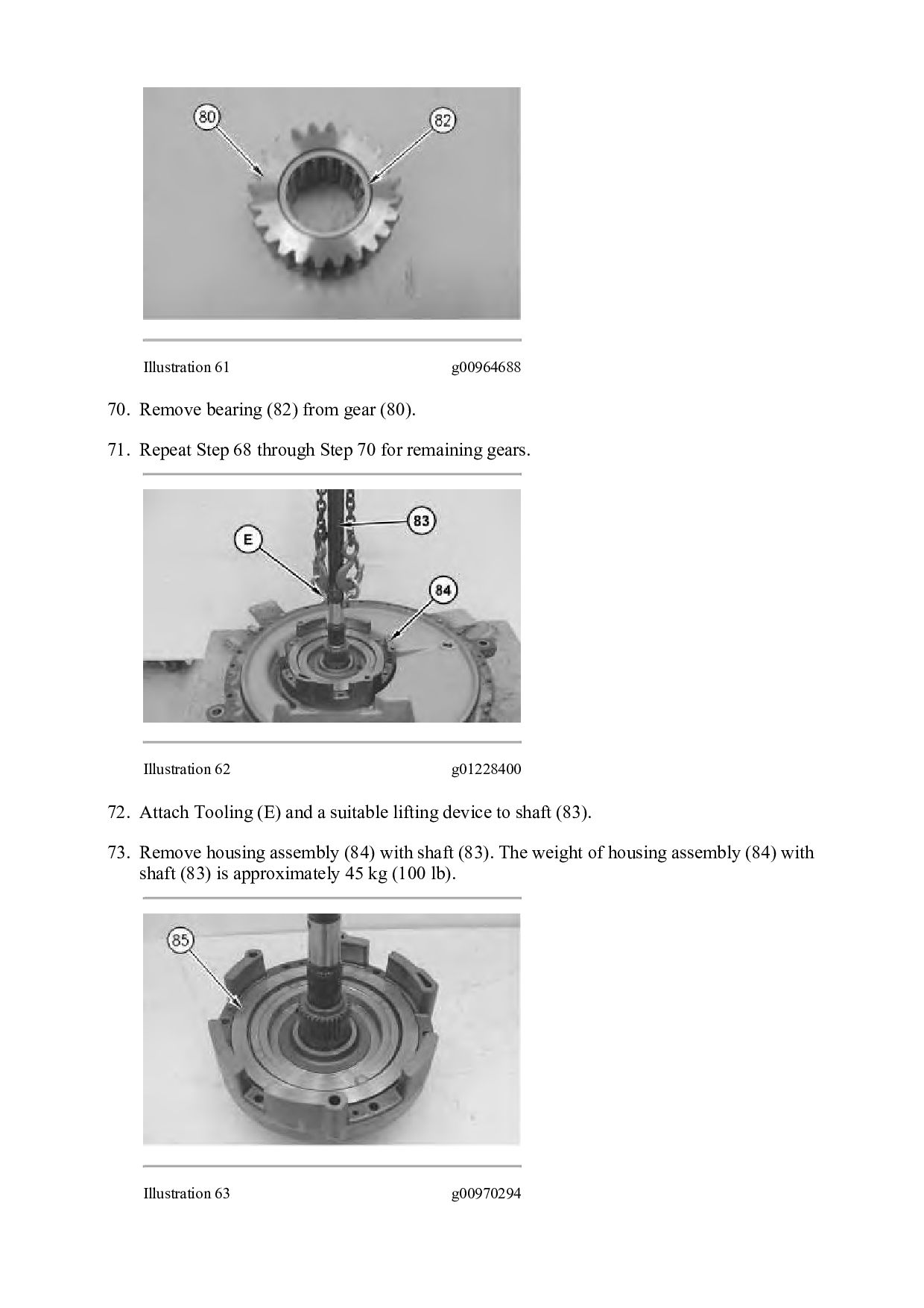
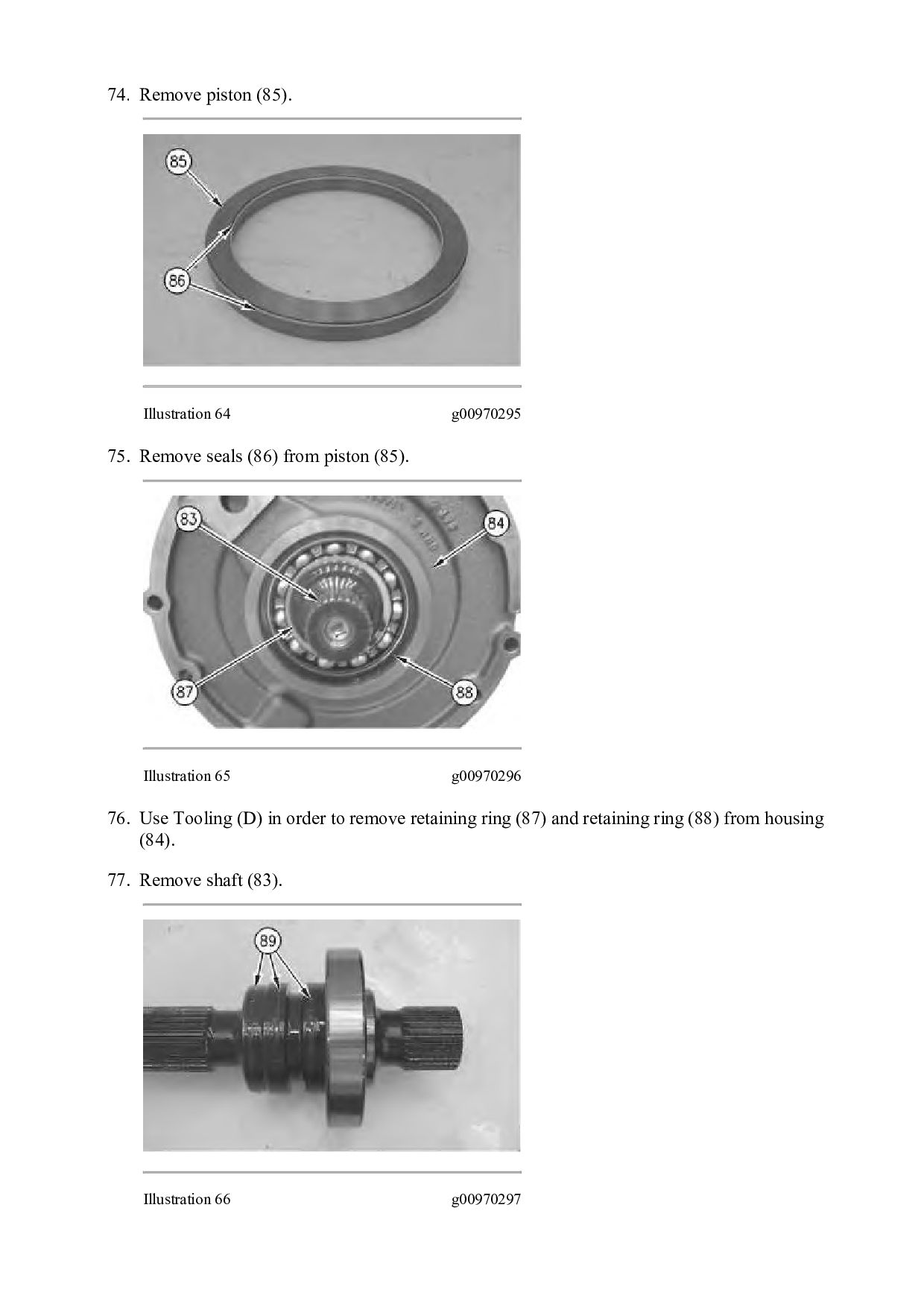
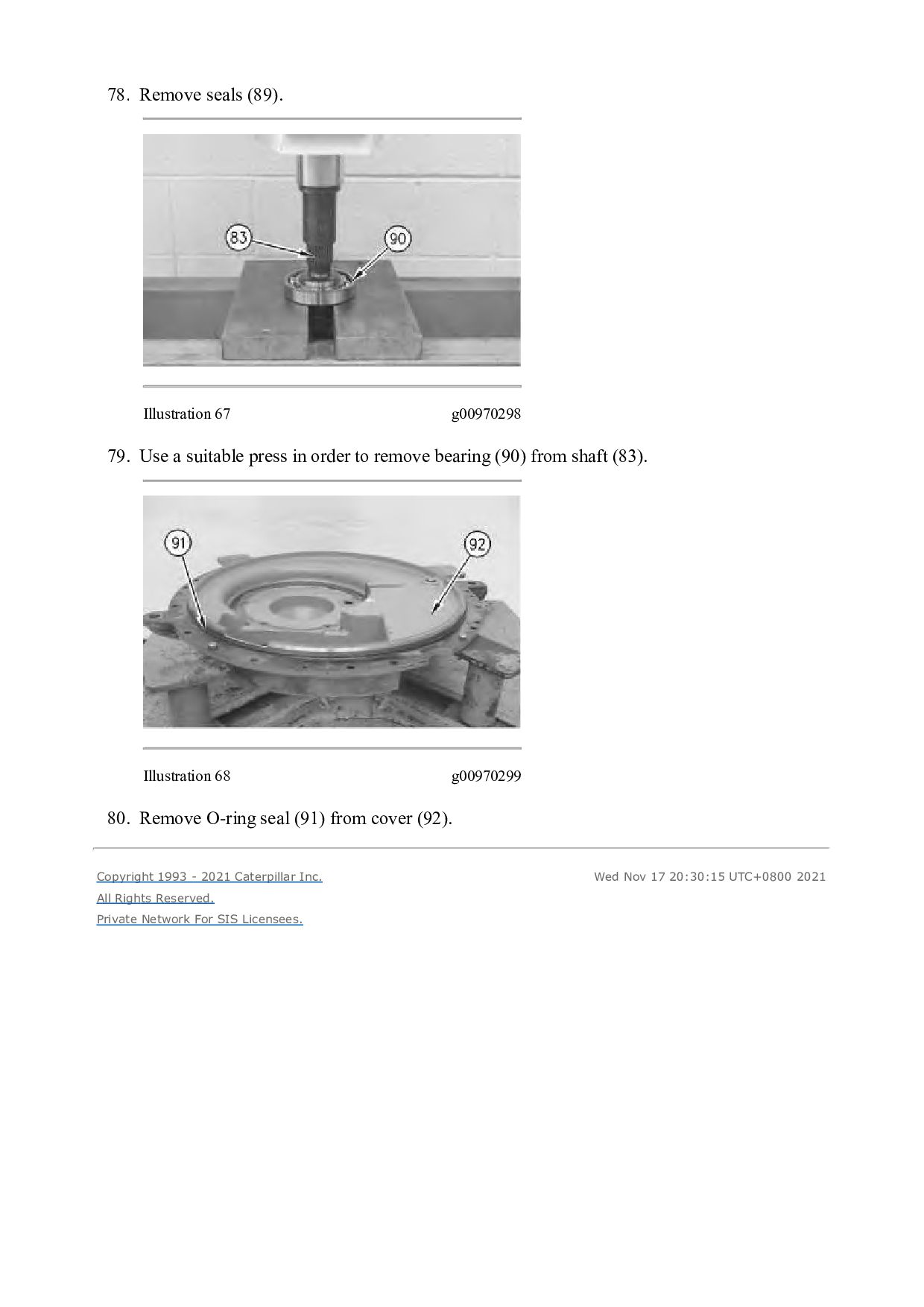
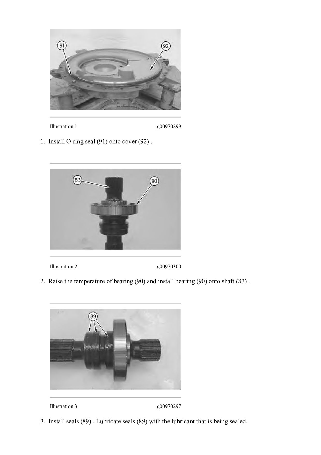
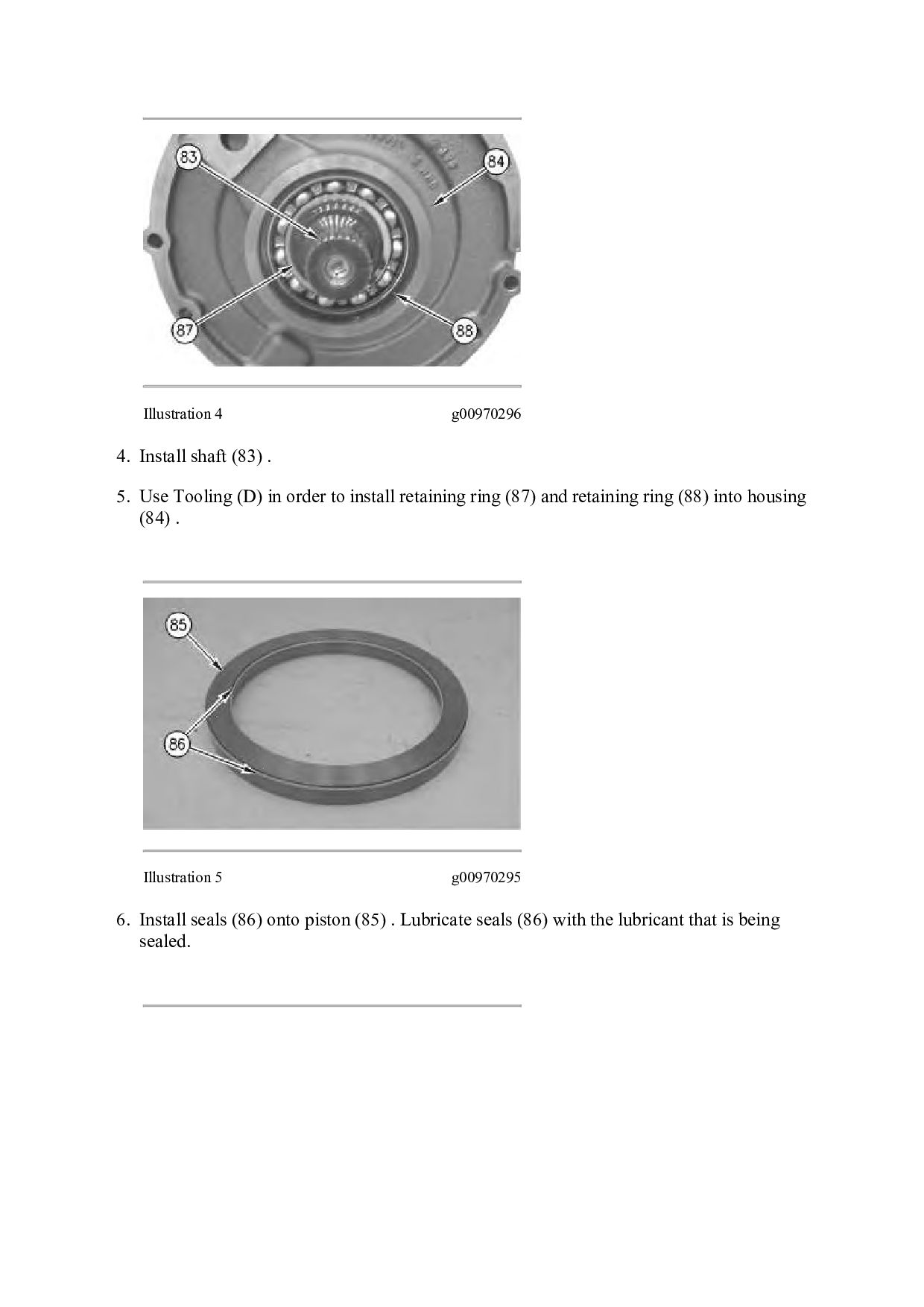
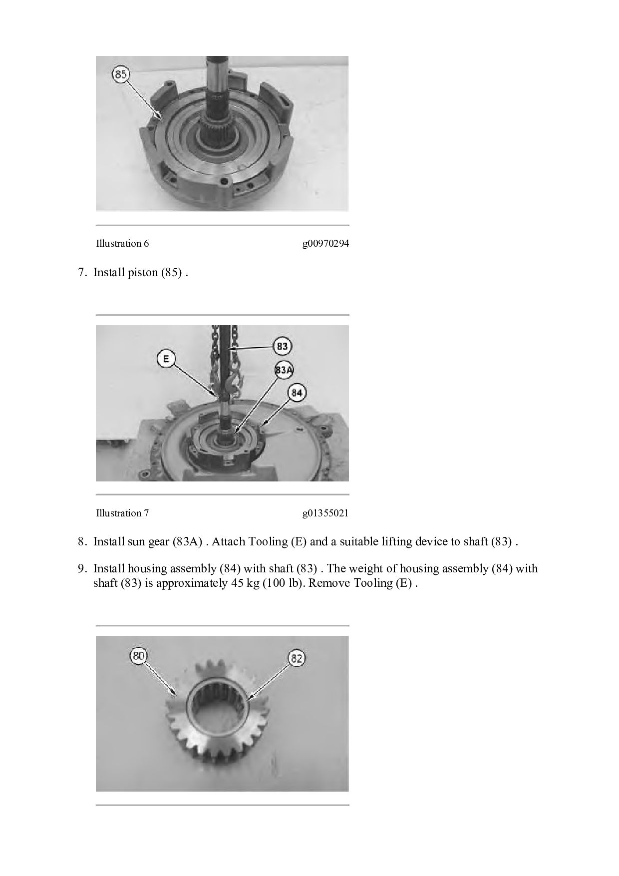
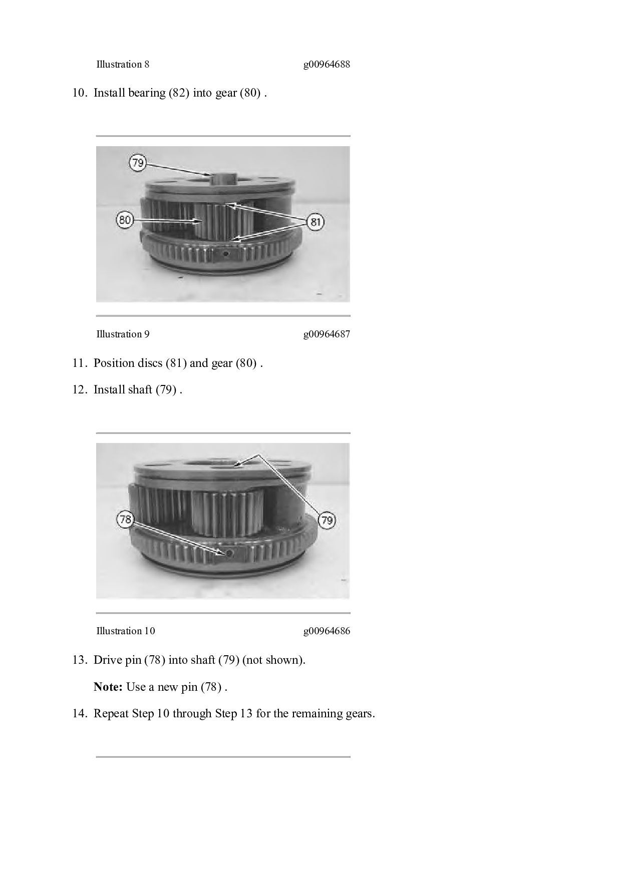
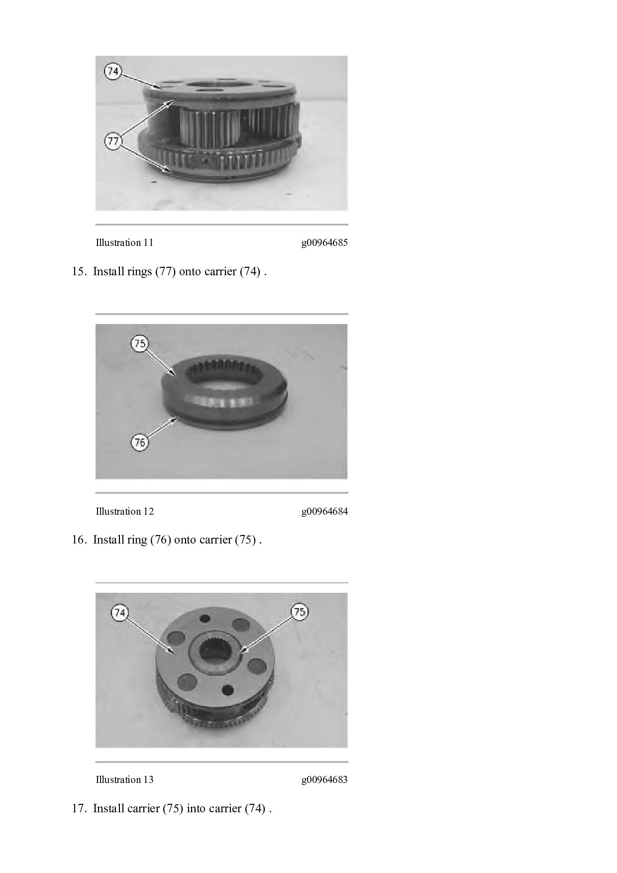
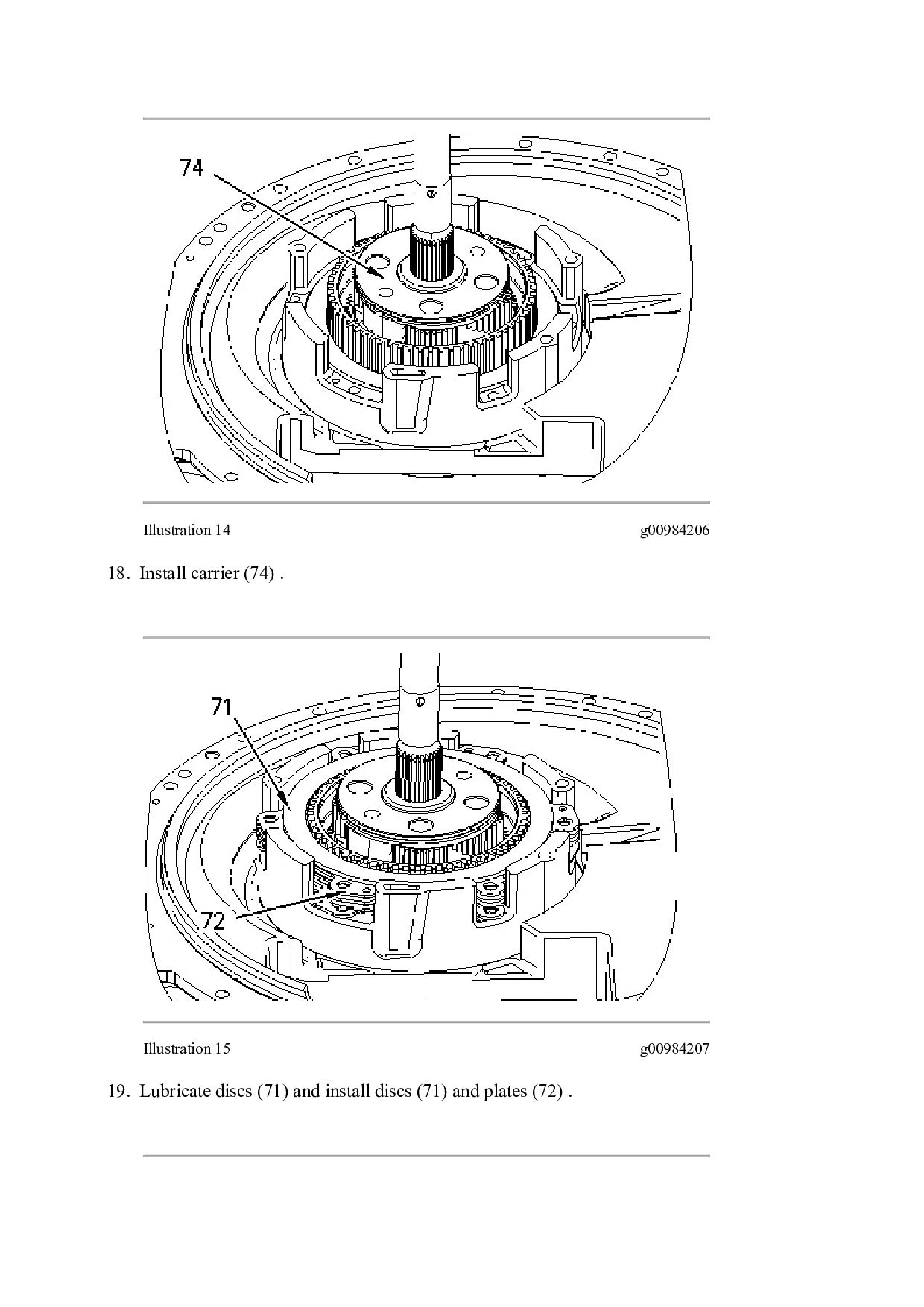
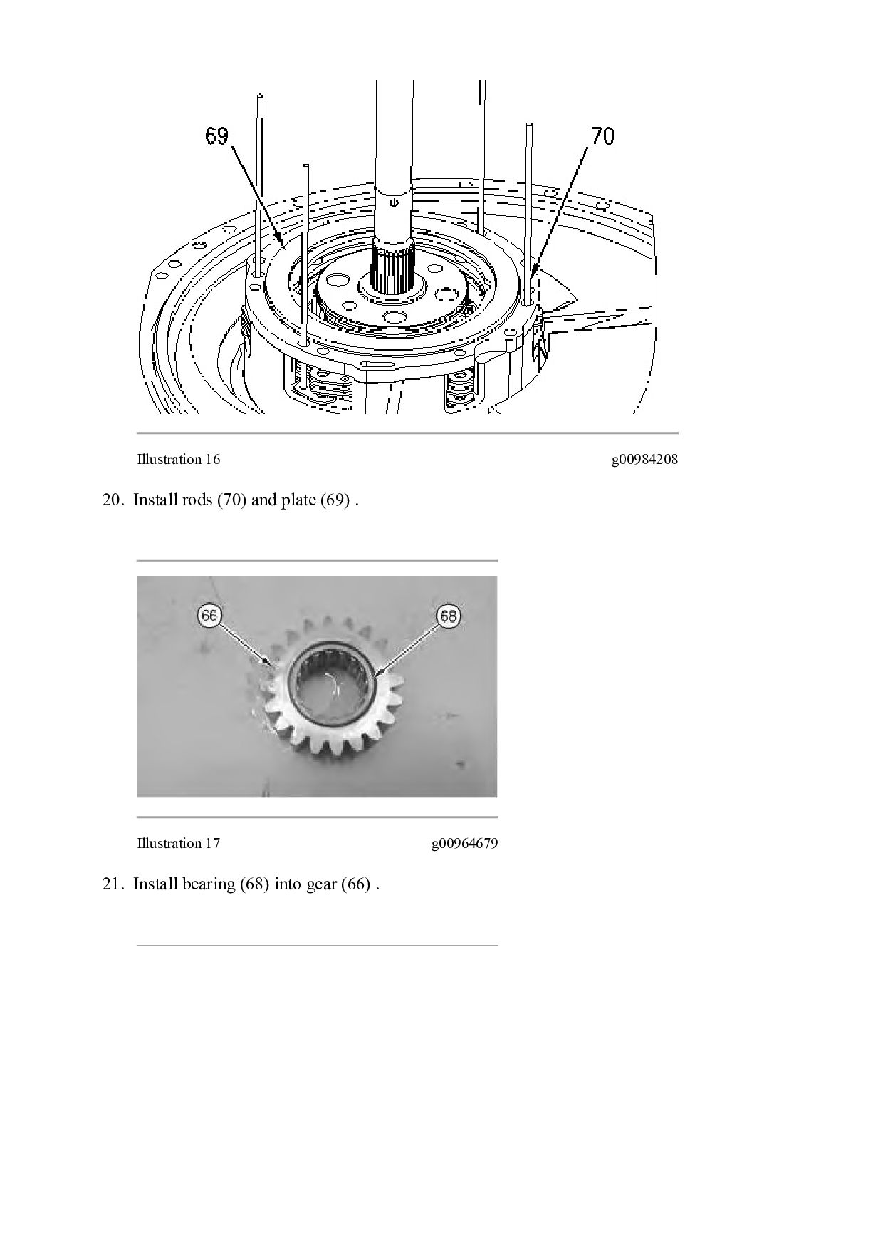
TRACTOR ALY Configuration: D6N XL, D/S, LGP TRACK-TYPE TRACTOR ALY00001-UP (MACHINE) POWERED BY 3126B Engine Disassembly and Assembly D6N Track-Type Tractor Power Train Media Number -RENR5257-04 Publication Date -01/12/2015 Date Updated -15/12/2015 i02461619 Transmission - Disassemble SMCS - 3030-015 Disassembly Procedure Table 1 Required Tools Tool Part Number Part Description Qty A 1P-1864 Retaining Ring Pliers 1 B 136-1452 Retaining Ring Pliers 1 C 9U-7480 Compressing Tube 1 D 1P-1863 Retaining Ring Pliers 1 E 138-7573 Link Bracket 2 Start By: a. Separate the transmission and bevel gear. Refer to Disassembly and Assembly, "Transmission and Bevel Gear - Seperate". NOTICE Care must be taken to ensure that fluids are contained during performance of inspection, maintenance, testing, adjusting, and repair of the product. Be prepared to collect the fluid with suitable containers before opening any compartment or disassembling any component containing fluids.