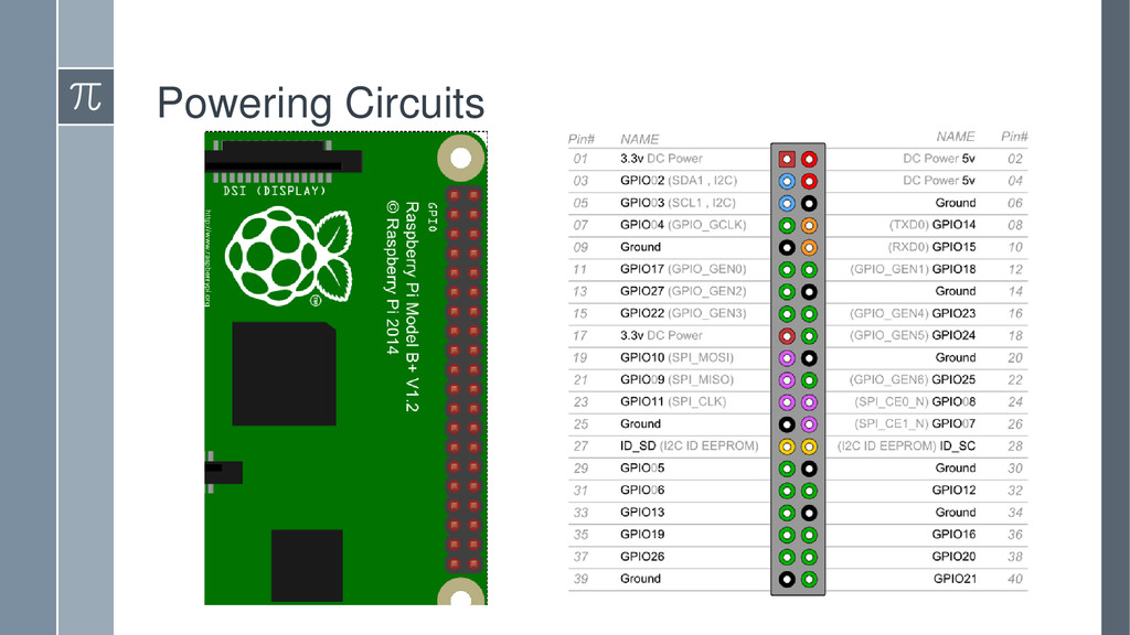
You've heard lots of hype about the Raspberry Pi, the credit-card sized computer available for under $40. This talk will introduce some of the Pi's features, explore some sample projects you can create, and show you how to write code to control hardware through it's IO pins. After this talk you will be ready to make your own cool hacking projects with the Pi.
![Code 17.while True: 18. for i in range(len(pins)): 19. GPIO.output(pins[i],](https://files.speakerdeck.com/presentations/b30f30bf5afd4b76bc55e8b28c689855/slide_28.jpg)
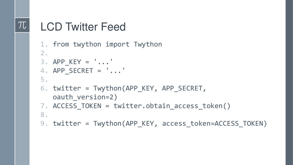
![LCD Twitter Feed 10.tweets = twitter.search(q='#KCDCpi') 11. print(tweets["u'statuses'"][0]["u'user'"]["u'screen_name'"]) 12.print(tweets["u'statuses'"][0]["u'text'"])](https://files.speakerdeck.com/presentations/b30f30bf5afd4b76bc55e8b28c689855/slide_43.jpg)
![Contact Me Twitter: @geekygirlsarah Email: [email protected] Slides/Resources: sarahwithee.com/raspberrypi › Feel](https://files.speakerdeck.com/presentations/b30f30bf5afd4b76bc55e8b28c689855/slide_62.jpg)