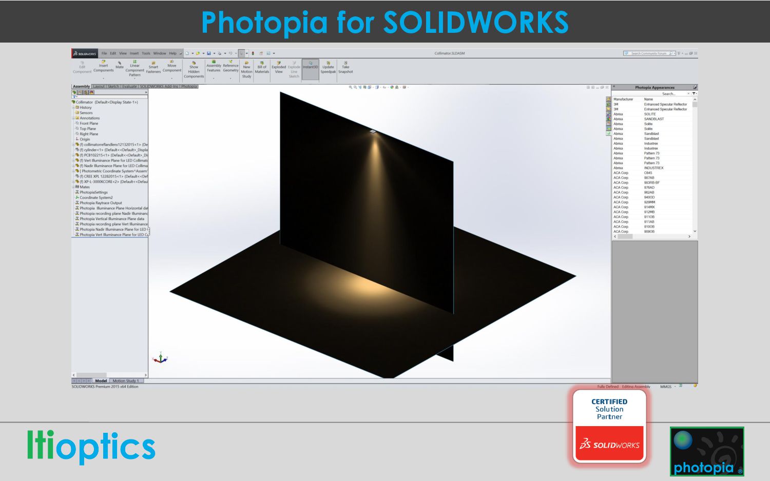
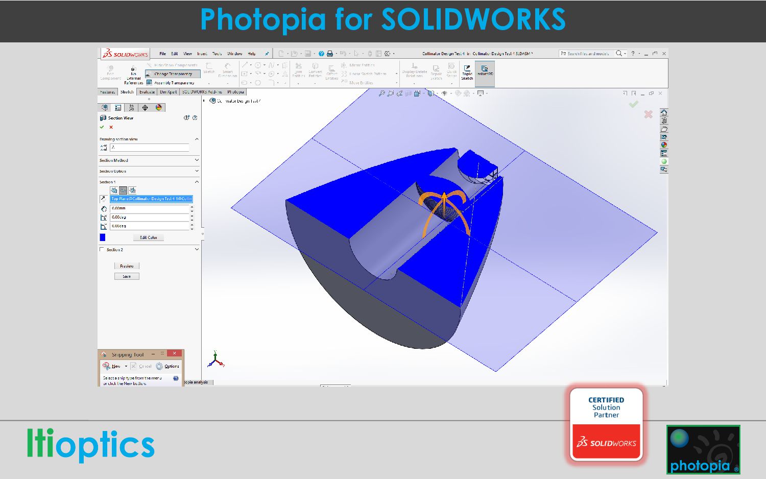
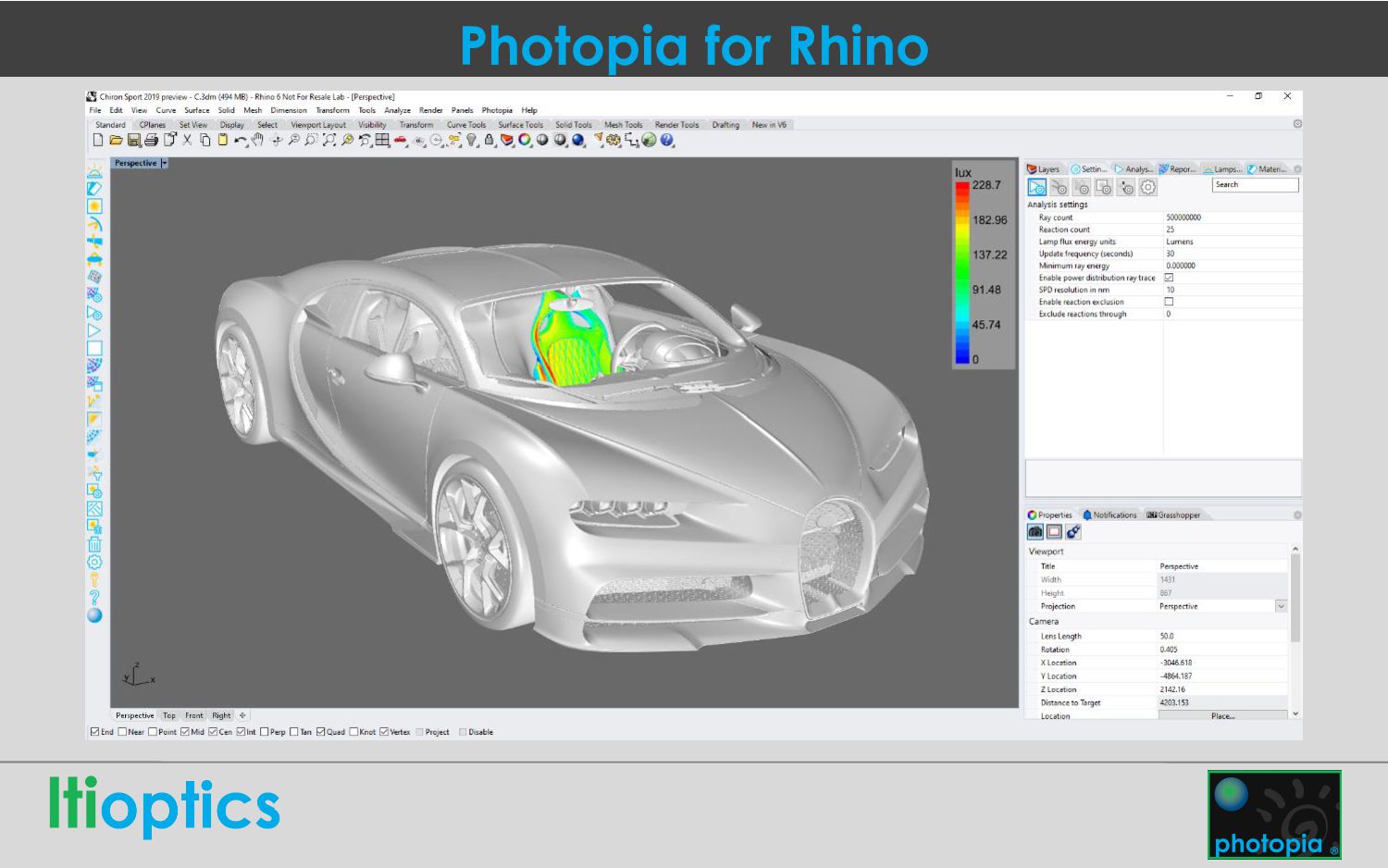
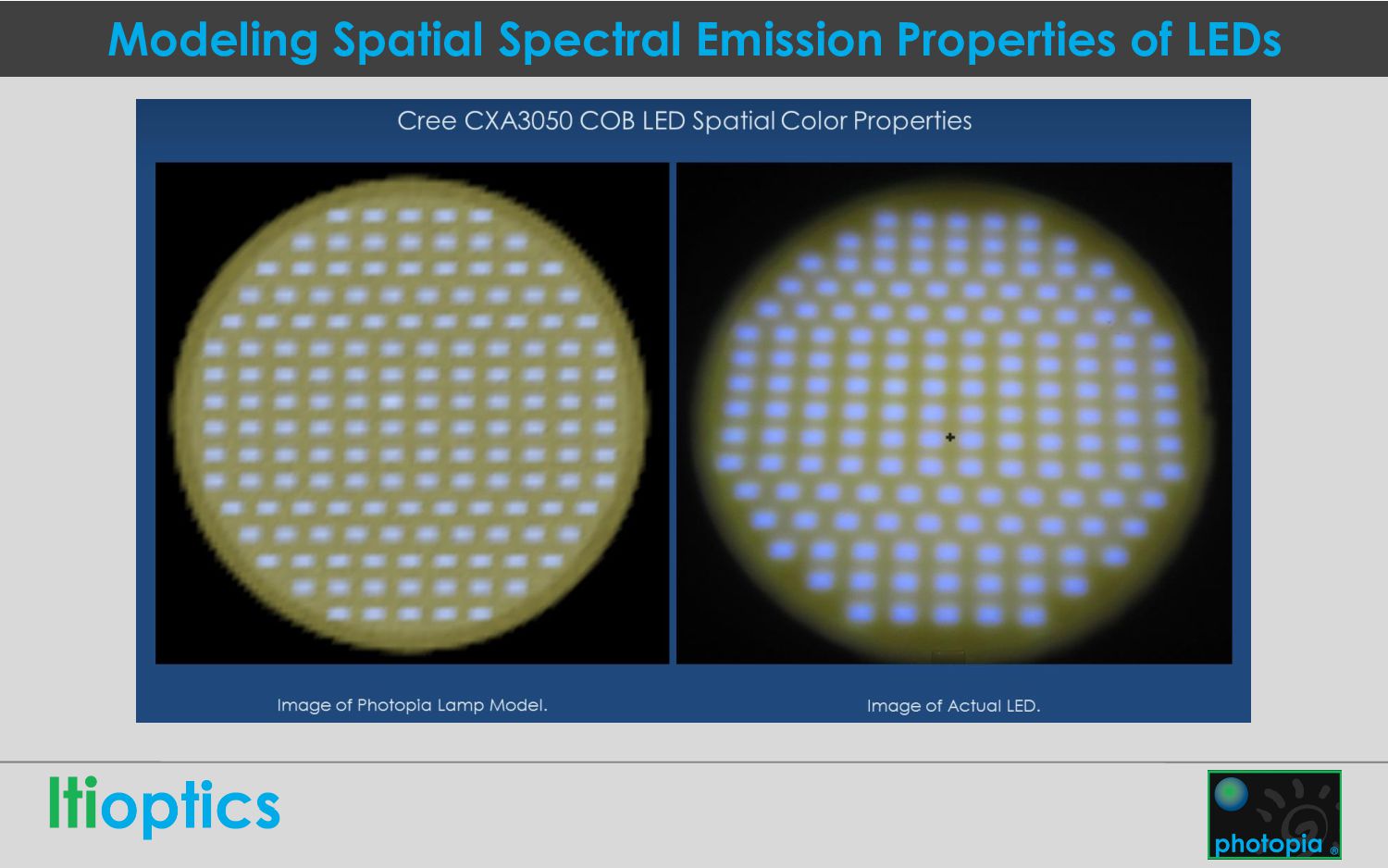
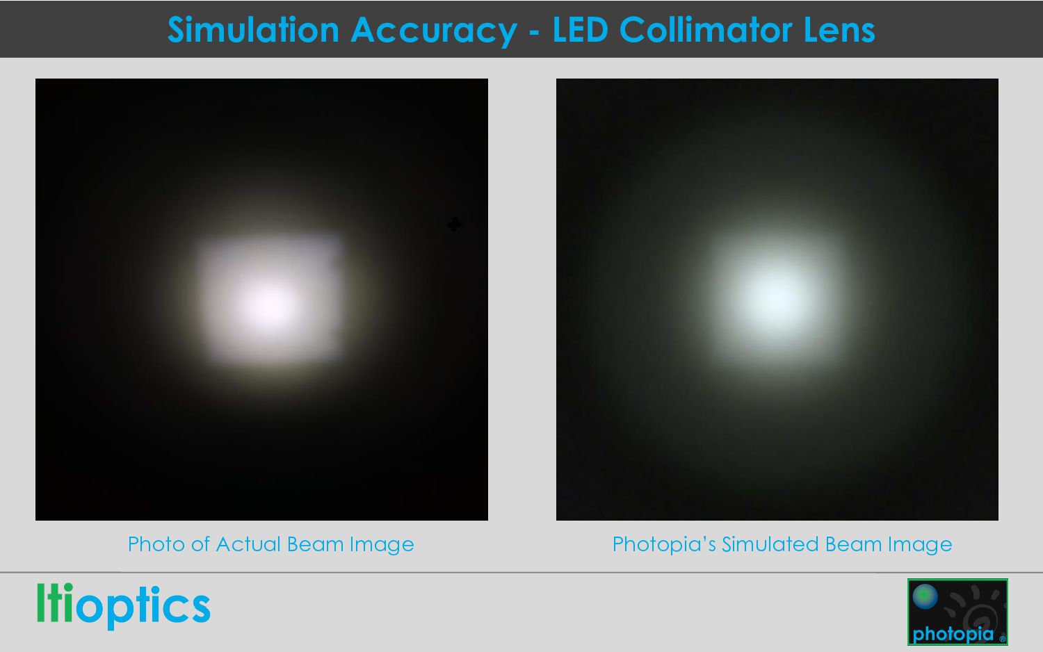
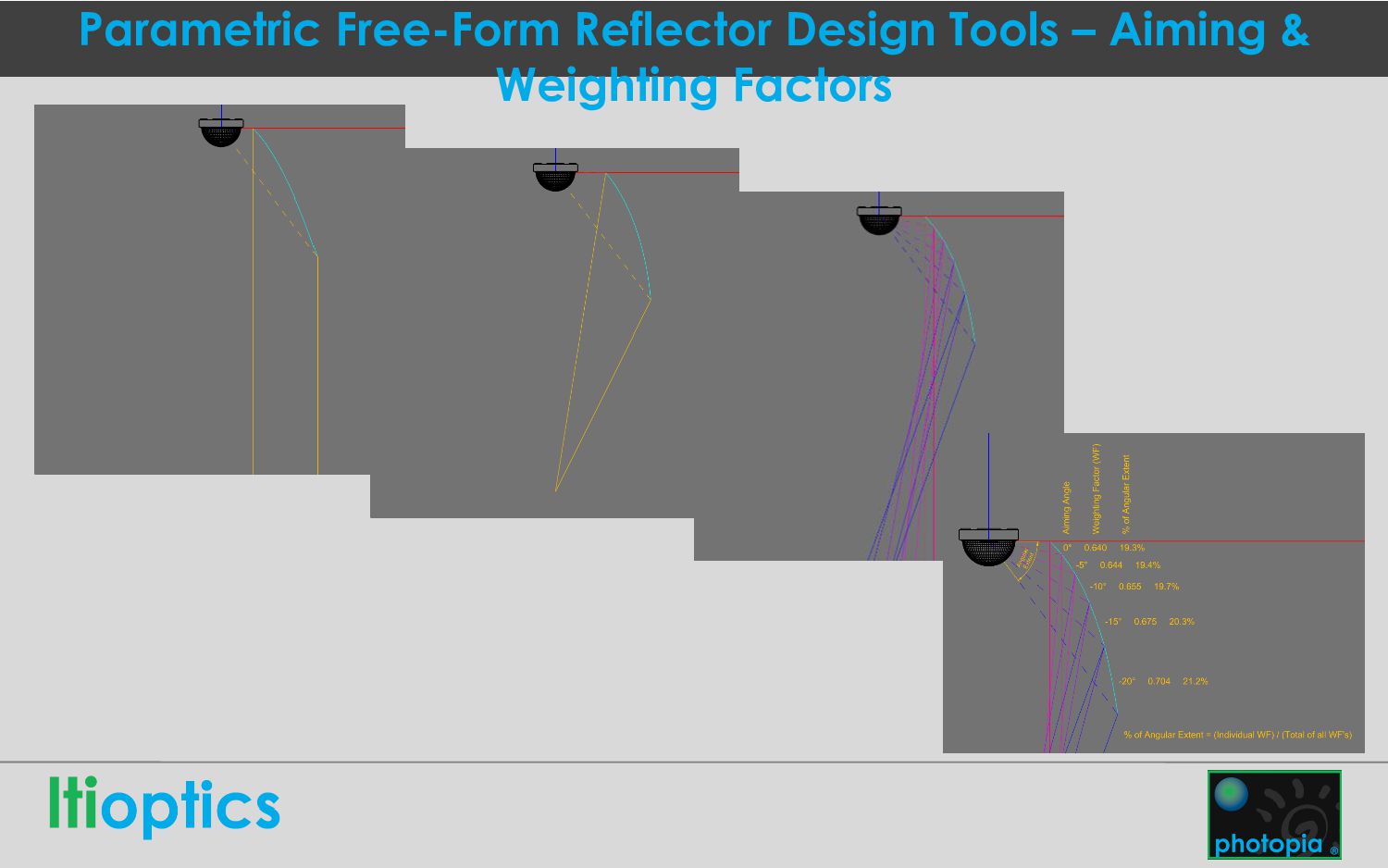
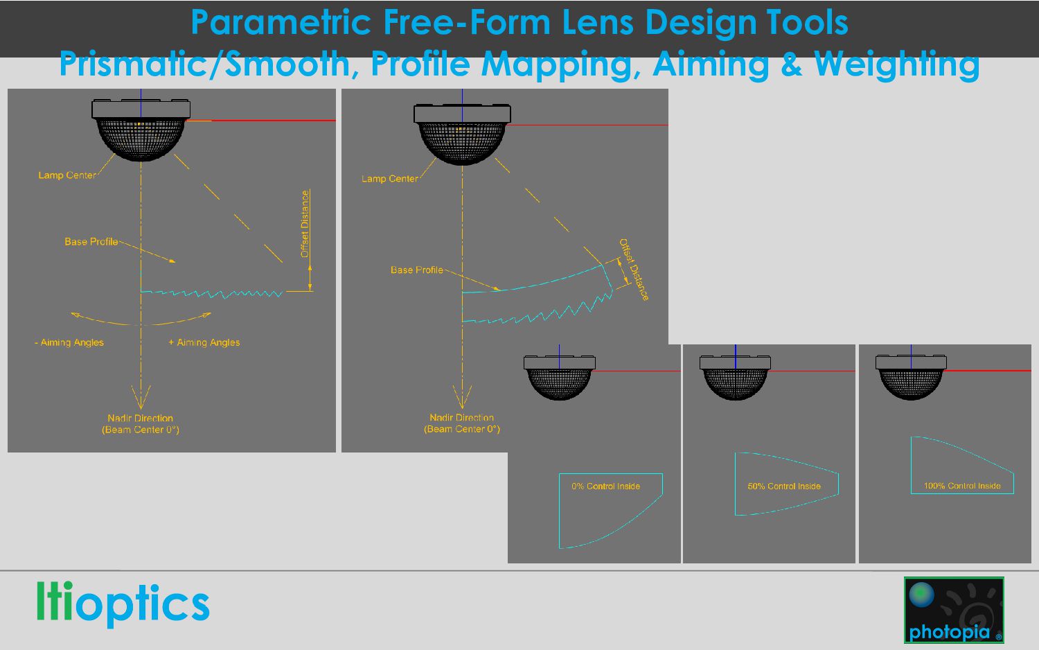
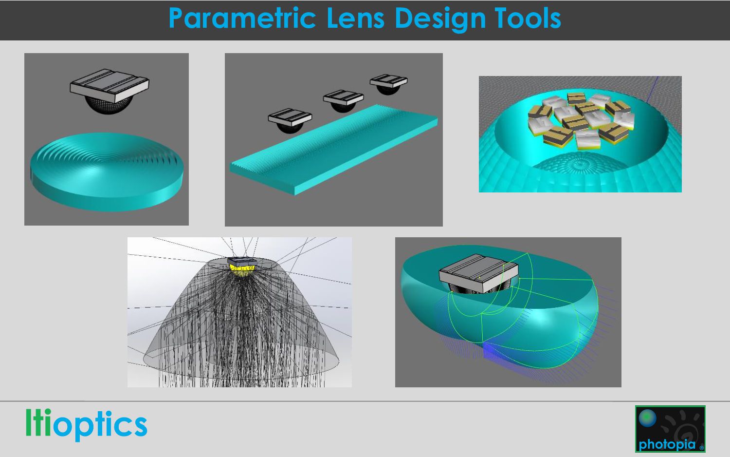
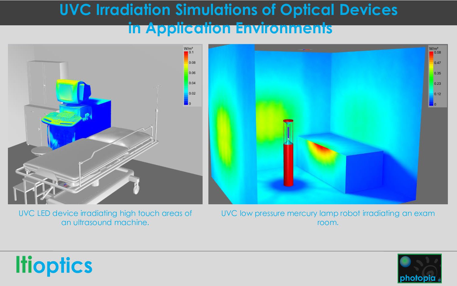
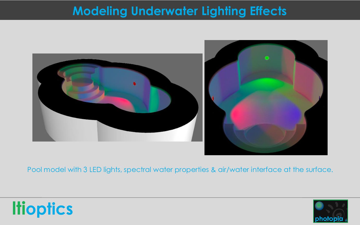
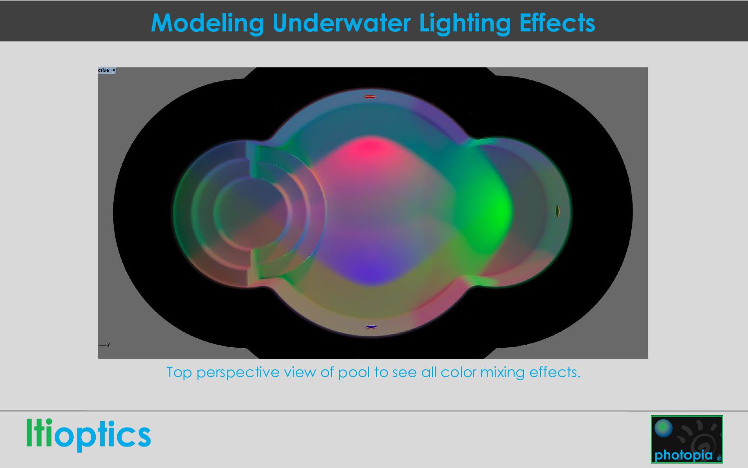
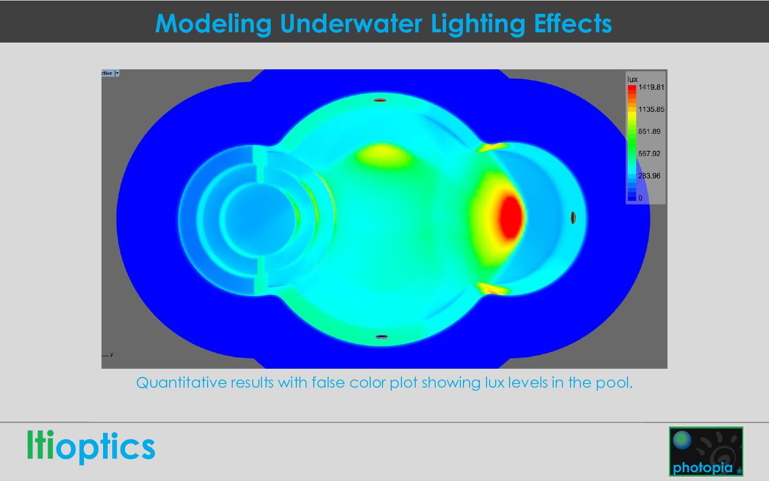
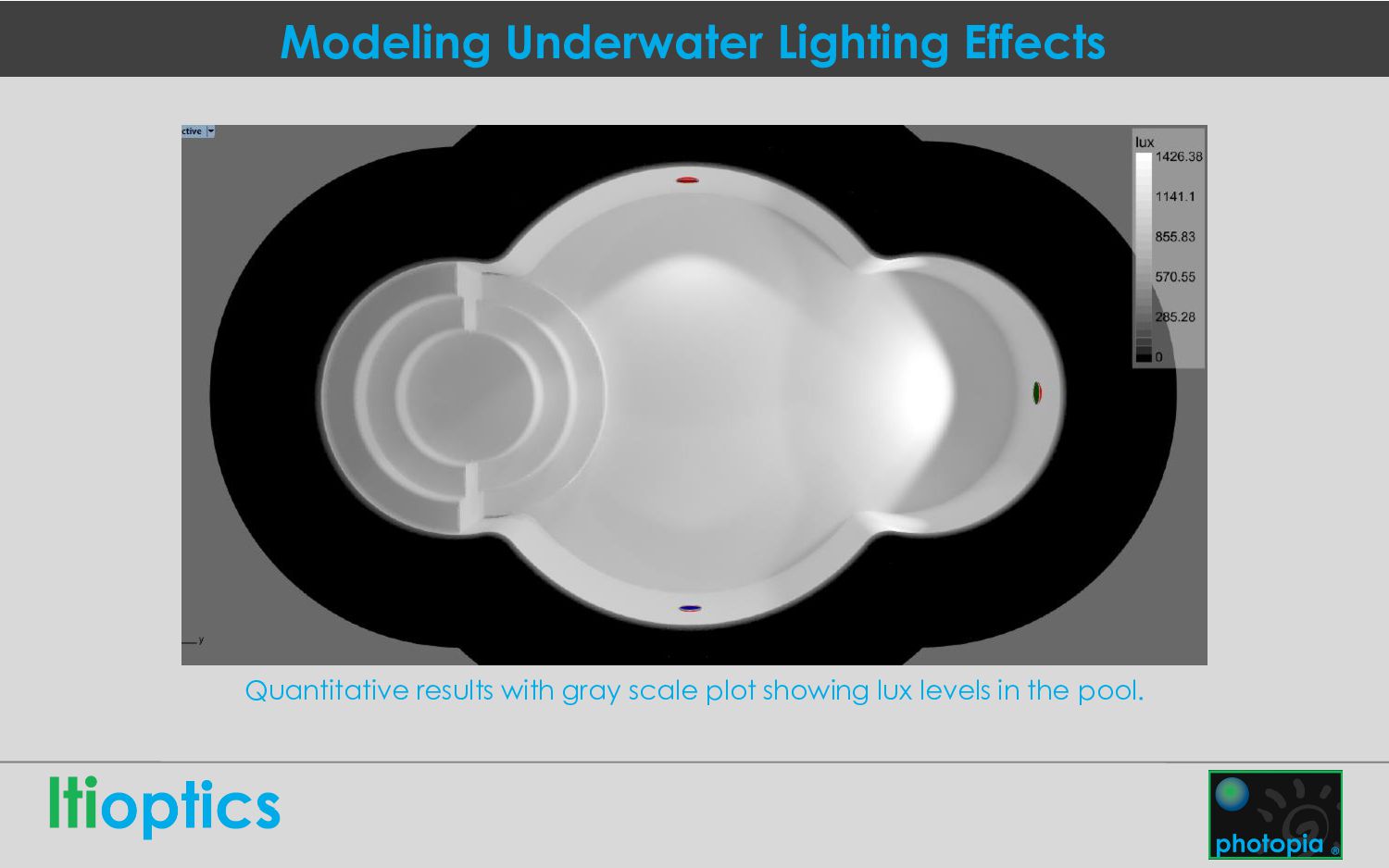
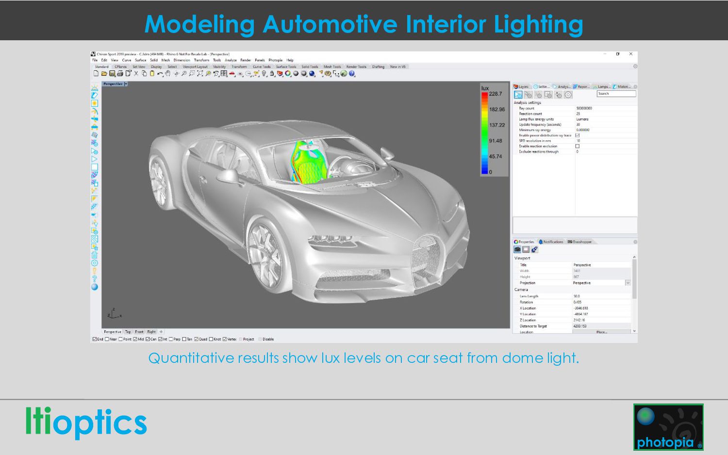
engineers to virtually prototype the performance of non-imaging optical systems before building physical prototypes. Photopia’s monte-carlo raytracing engine works inside of Solidworks or Rhino and is compatible with Inventor, Fusion, Catia, Creo, Pro/E and many other CAD softwares. https://www.ltioptics.com/
and sells Photopia optical design software. We are a small company located in Westminster Colorado supporting our software around the entire globe. Members of our team have been working on Photopia and its predecessor since the 1990’s, continually improving and refining our raytracing and optical design engines. https://www.ltioptics.com/
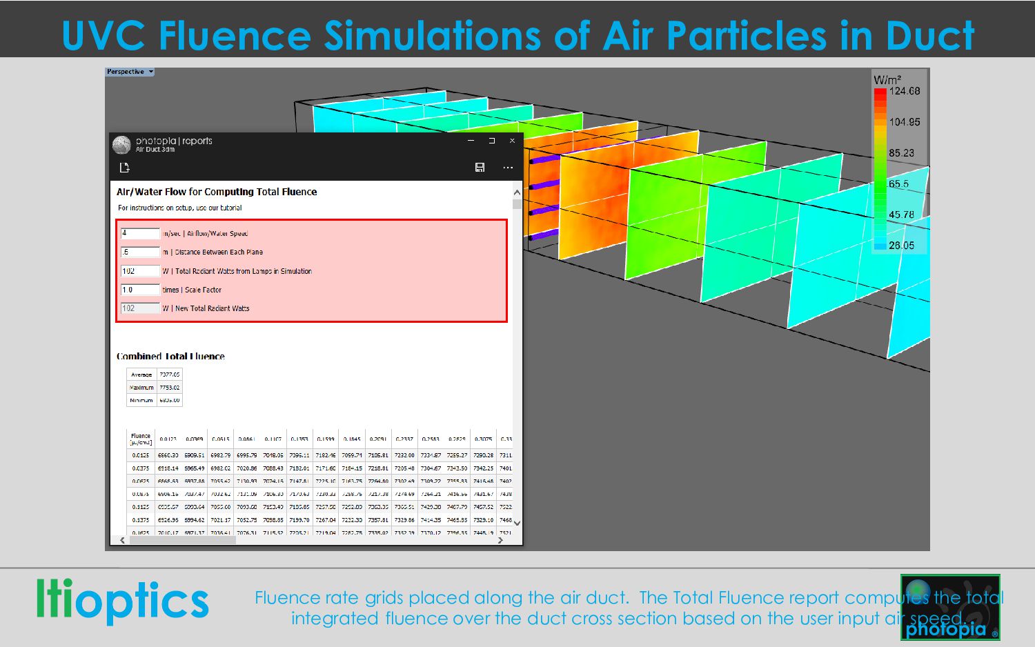
grids placed along the air duct. The Total Fluence report computes the total integrated fluence over the duct cross section based on the user input air speed.
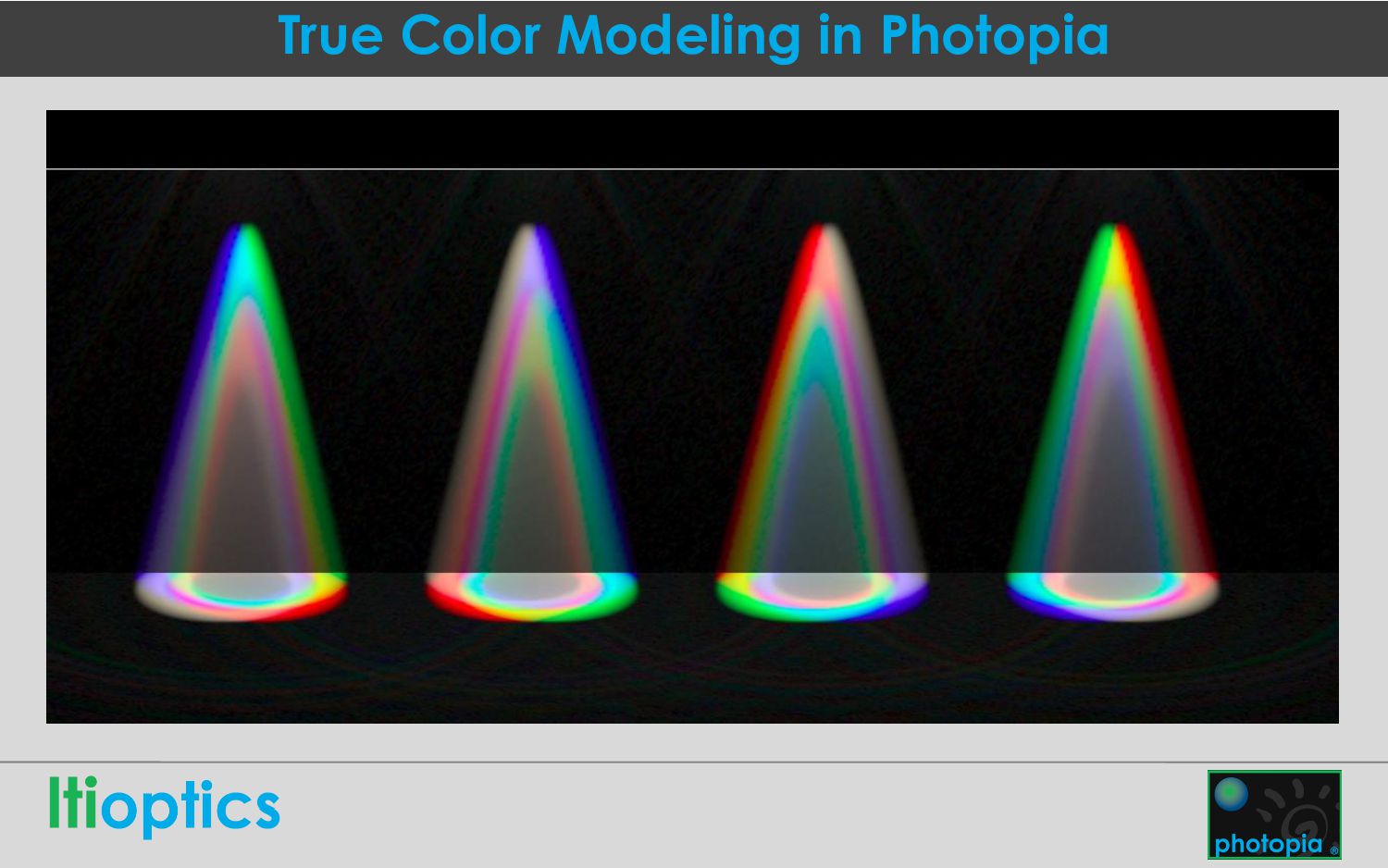
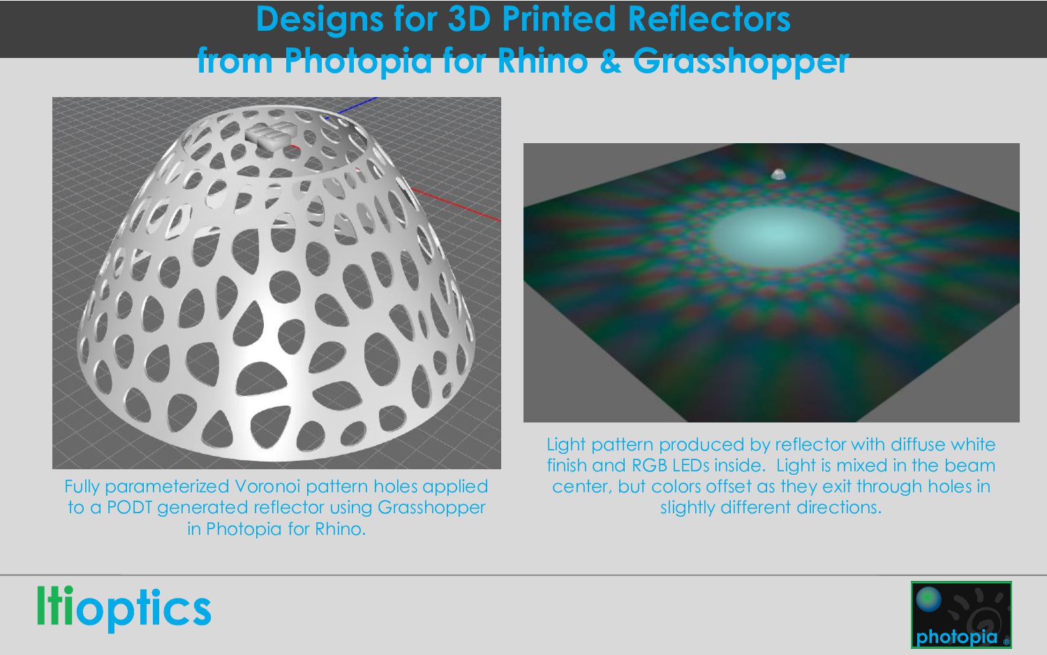
Grasshopper Fully parameterized Voronoi pattern holes applied to a PODT generated reflector using Grasshopper in Photopia for Rhino. Light pattern produced by reflector with diffuse white finish and RGB LEDs inside. Light is mixed in the beam center, but colors offset as they exit through holes in slightly different directions.
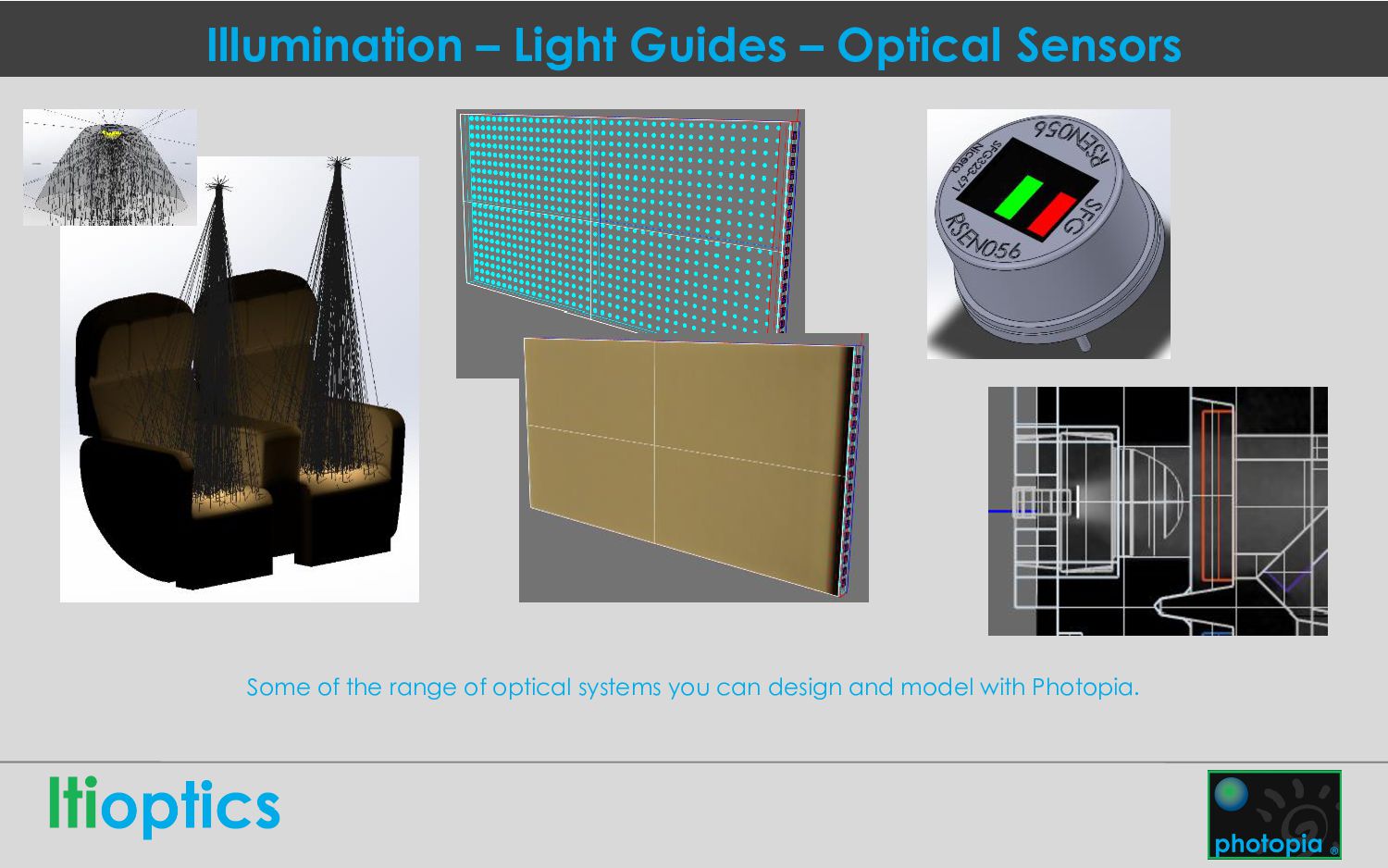
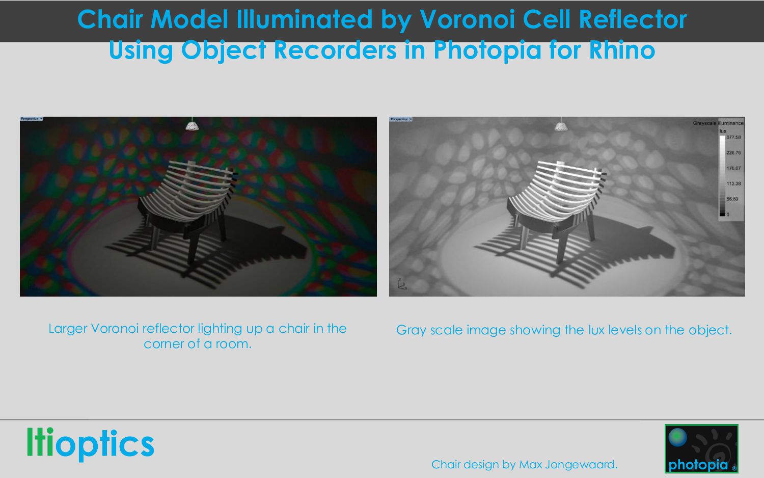
in Photopia for Rhino Larger Voronoi reflector lighting up a chair in the corner of a room. Gray scale image showing the lux levels on the object. Chair design by Max Jongewaard.
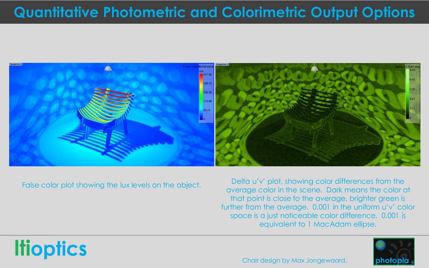
the lux levels on the object. Delta u’v’ plot, showing color differences from the average color in the scene. Dark means the color at that point is close to the average, brighter green is further from the average. 0.001 in the uniform u’v’ color space is a just noticeable color difference. 0.001 is equivalent to 1 MacAdam ellipse. Chair design by Max Jongewaard.
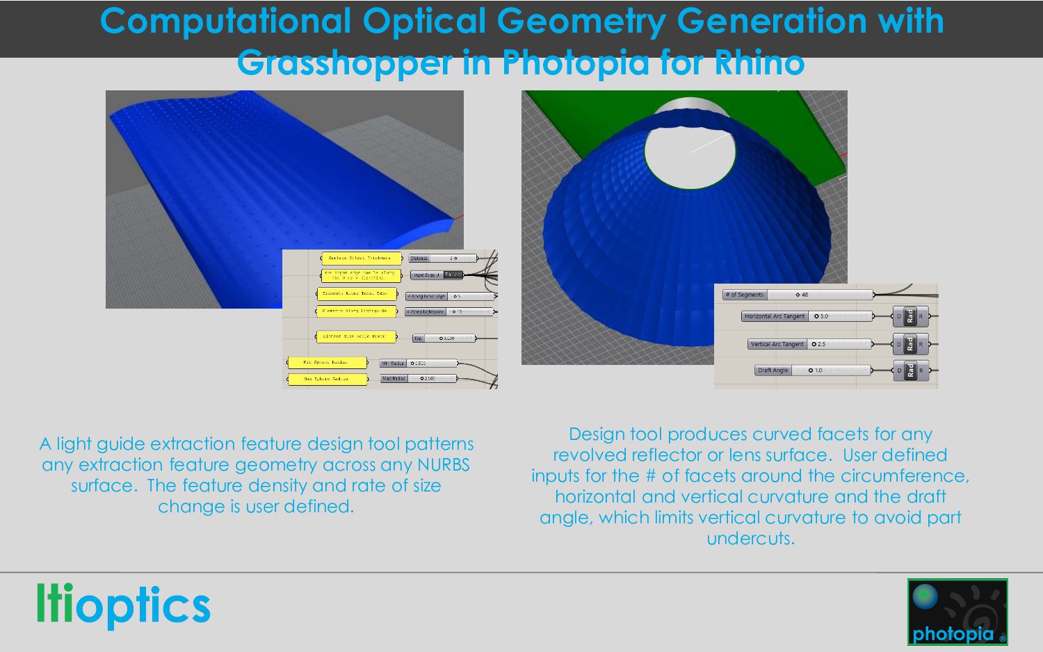
A light guide extraction feature design tool patterns any extraction feature geometry across any NURBS surface. The feature density and rate of size change is user defined. Design tool produces curved facets for any revolved reflector or lens surface. User defined inputs for the # of facets around the circumference, horizontal and vertical curvature and the draft angle, which limits vertical curvature to avoid part undercuts.
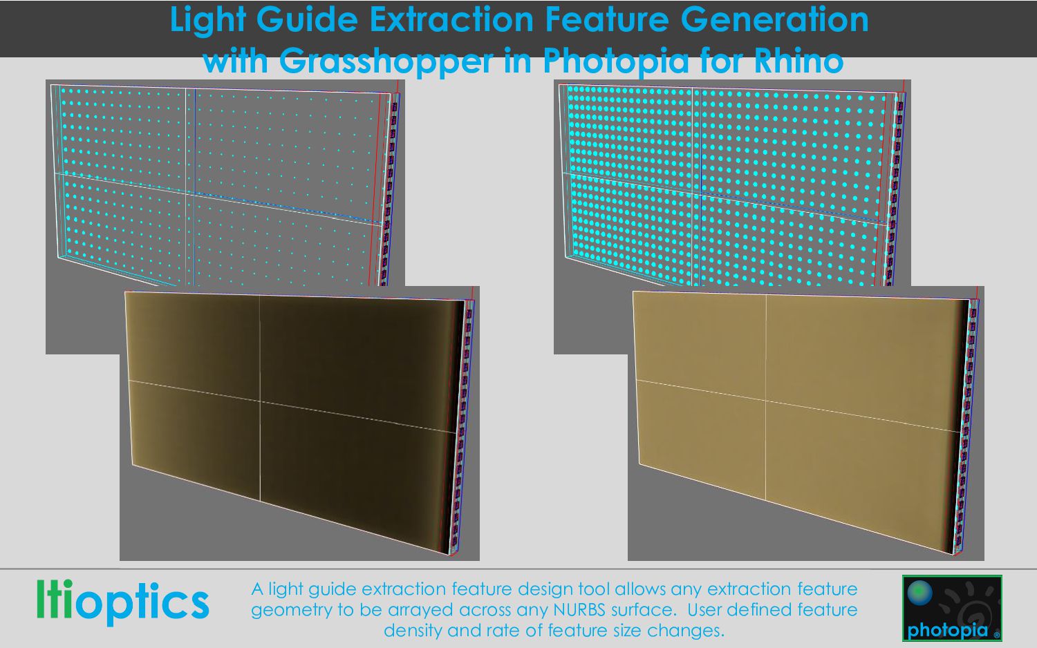
Rhino A light guide extraction feature design tool allows any extraction feature geometry to be arrayed across any NURBS surface. User defined feature density and rate of feature size changes.
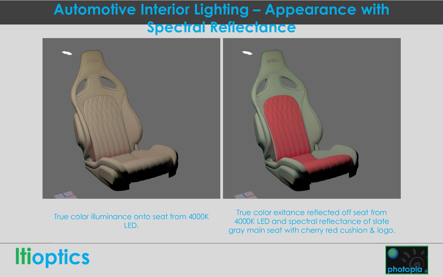
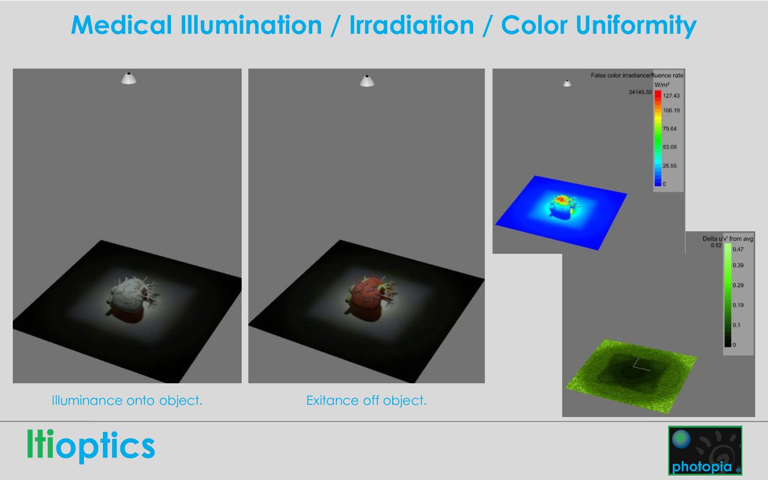
illuminance onto seat from 4000K LED. True color exitance reflected off seat from 4000K LED and spectral reflectance of slate gray main seat with cherry red cushion & logo.
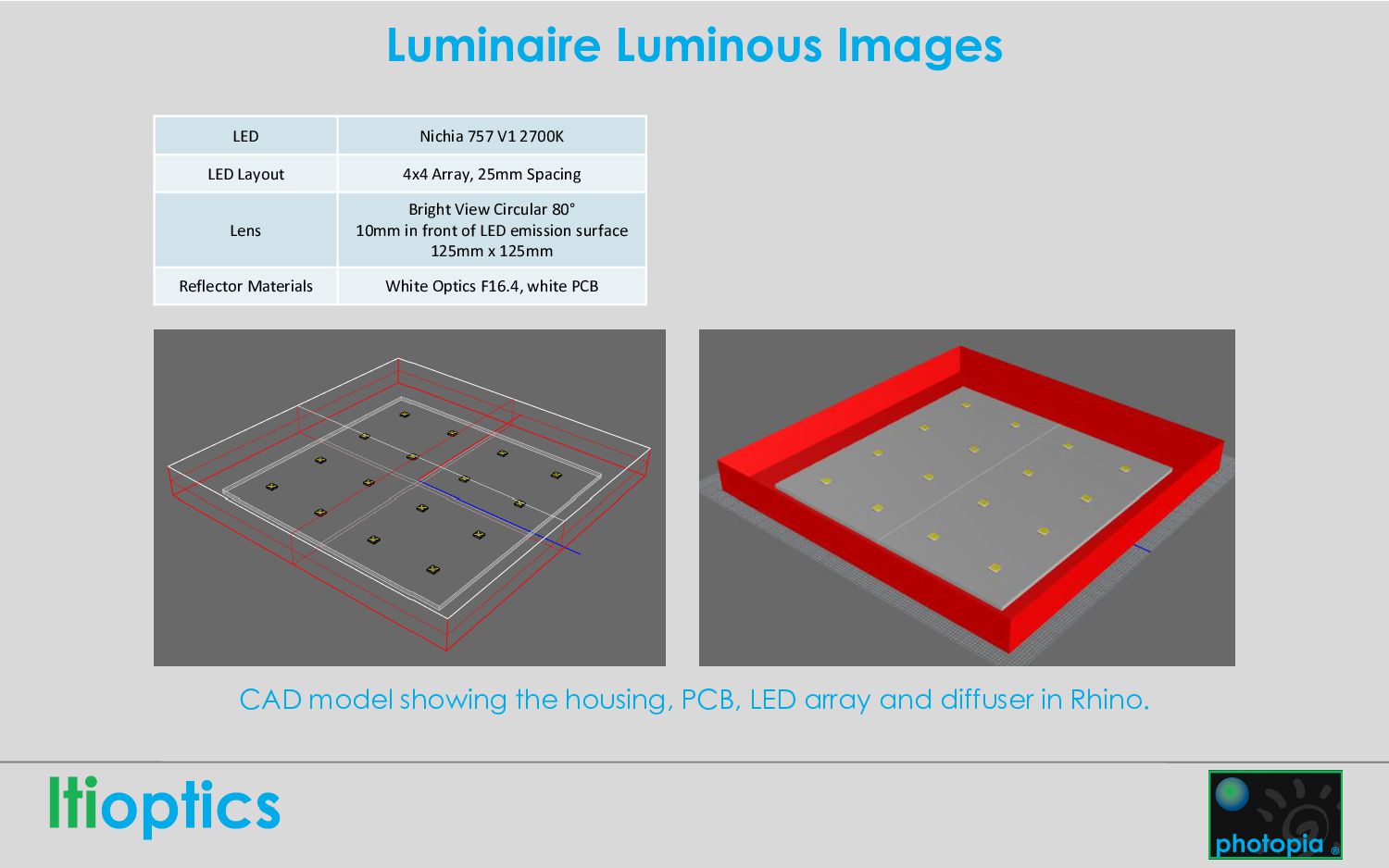
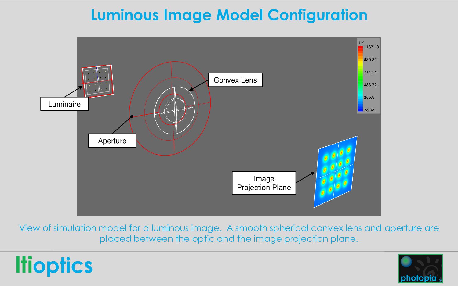
array and diffuser in Rhino. LED Nichia 757 V1 2700K LED Layout 4x4 Array, 25mm Spacing Lens Bright View Circular 80° 10mm in front of LED emission surface 125mm x 125mm Reflector Materials White Optics F16.4, white PCB
luminous image. A smooth spherical convex lens and aperture are placed between the optic and the image projection plane. Luminaire Convex Lens Aperture Image Projection Plane
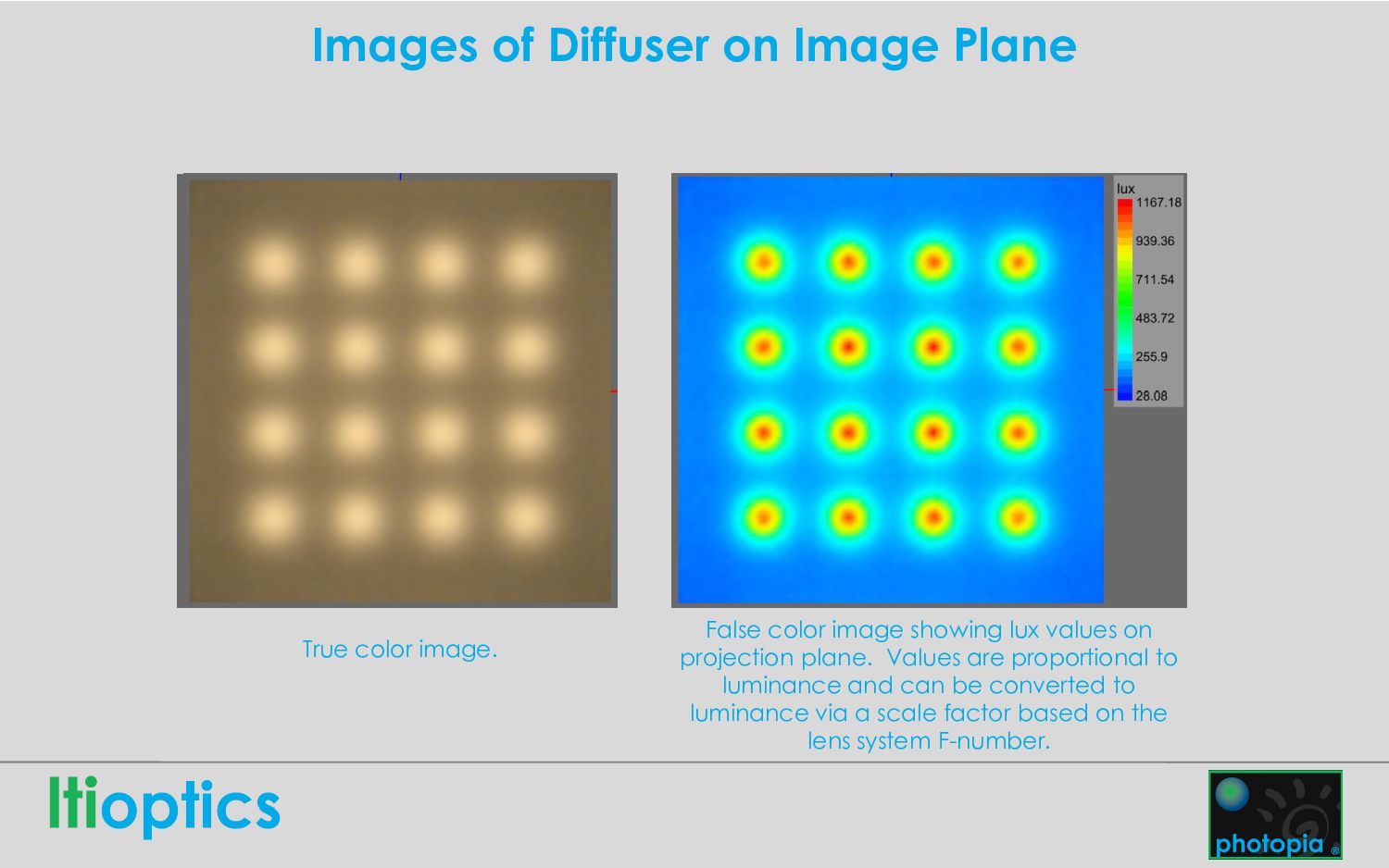
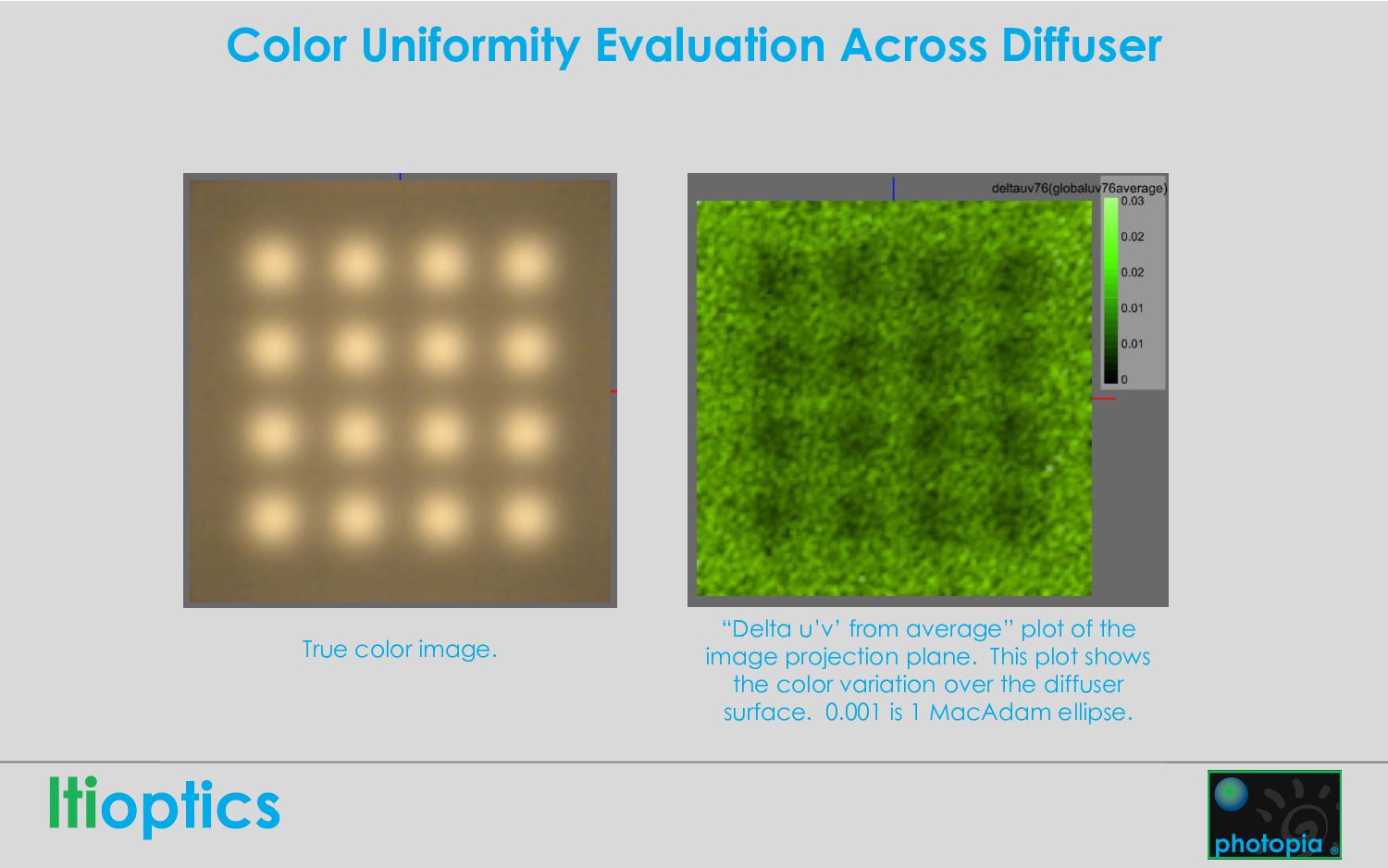
color image showing lux values on projection plane. Values are proportional to luminance and can be converted to luminance via a scale factor based on the lens system F-number.
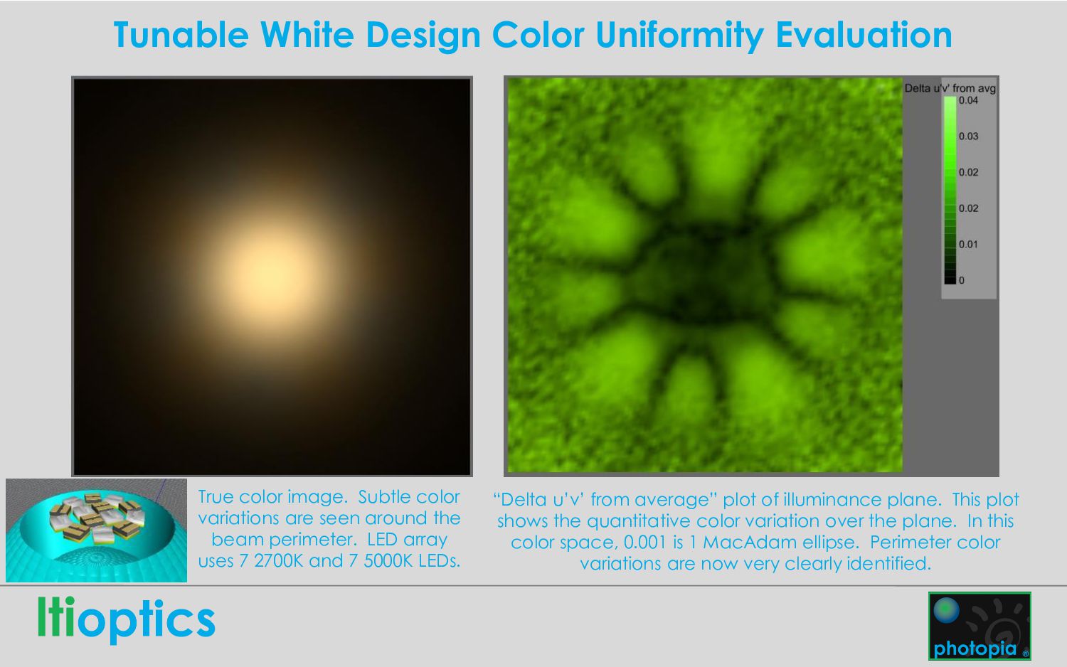
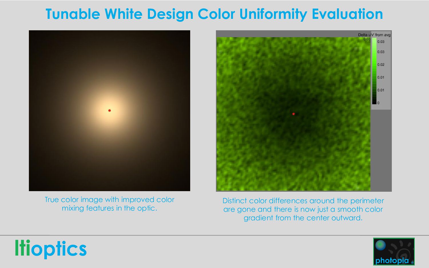
color variations are seen around the beam perimeter. LED array uses 7 2700K and 7 5000K LEDs. “Delta u’v’ from average” plot of illuminance plane. This plot shows the quantitative color variation over the plane. In this color space, 0.001 is 1 MacAdam ellipse. Perimeter color variations are now very clearly identified.
improved color mixing features in the optic. Distinct color differences around the perimeter are gone and there is now just a smooth color gradient from the center outward.
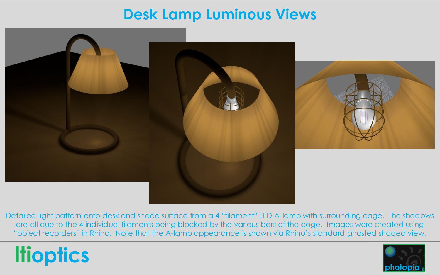
shade surface from a 4 “filament” LED A-lamp with surrounding cage. The shadows are all due to the 4 individual filaments being blocked by the various bars of the cage. Images were created using “object recorders” in Rhino. Note that the A-lamp appearance is shown via Rhino’s standard ghosted shaded view.
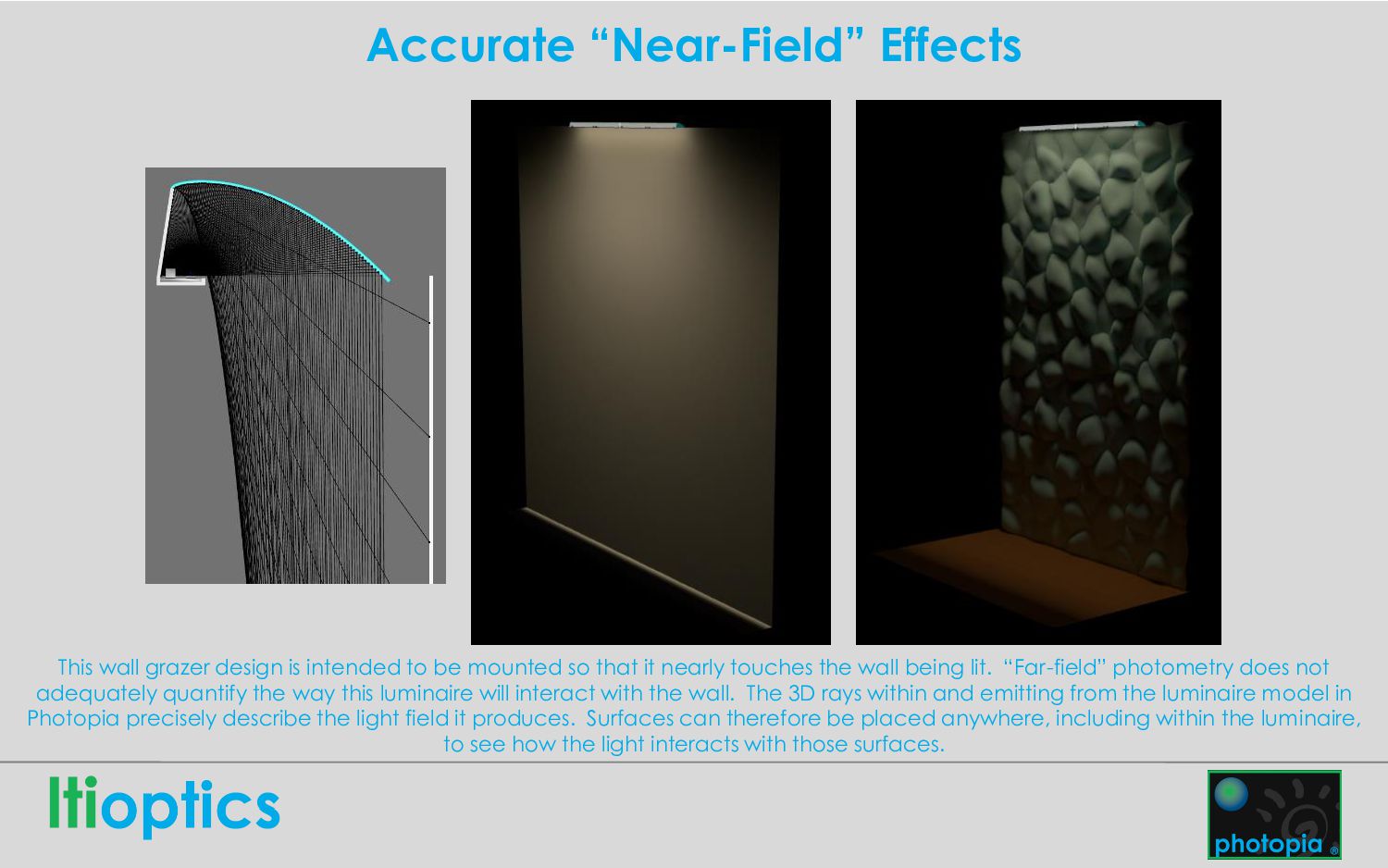
be mounted so that it nearly touches the wall being lit. “Far-field” photometry does not adequately quantify the way this luminaire will interact with the wall. The 3D rays within and emitting from the luminaire model in Photopia precisely describe the light field it produces. Surfaces can therefore be placed anywhere, including within the luminaire, to see how the light interacts with those surfaces.
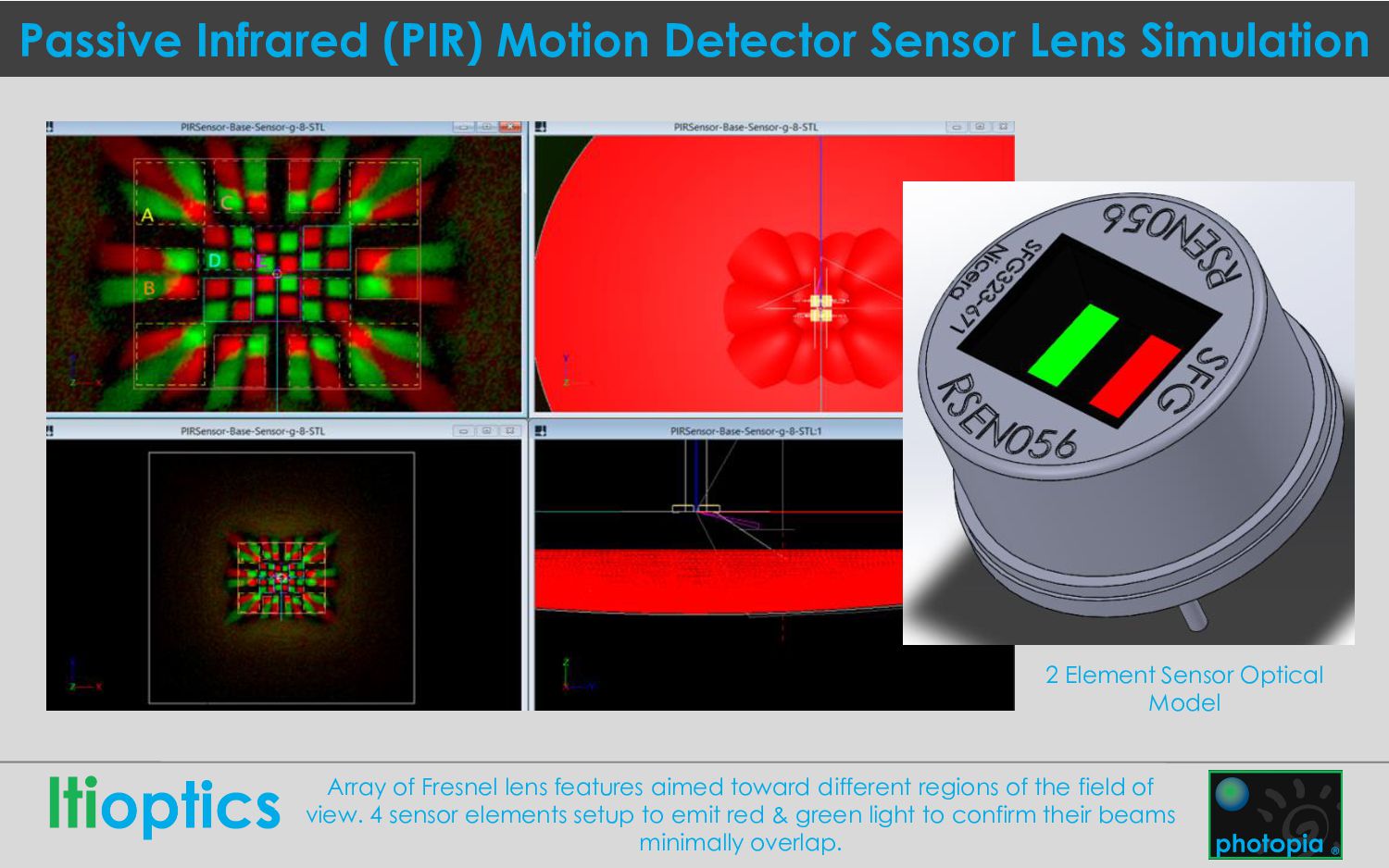
Sensor Optical Model Array of Fresnel lens features aimed toward different regions of the field of view. 4 sensor elements setup to emit red & green light to confirm their beams minimally overlap.


 occhi
 willnet
 kentarofujii
 kzkhykw1991
 pfn
 takahashim
 ivry_presentationmaterials
 recruitengineers
 nealle
 moznion
 sansantech
 skoyamalab
 mfonobong
 katarinadahlin
 eileencodes
 holman
 lara
 rocio
 jonoalderson
 stephenakadiri
 dougneiner
 csswizardry
 garrettdimon