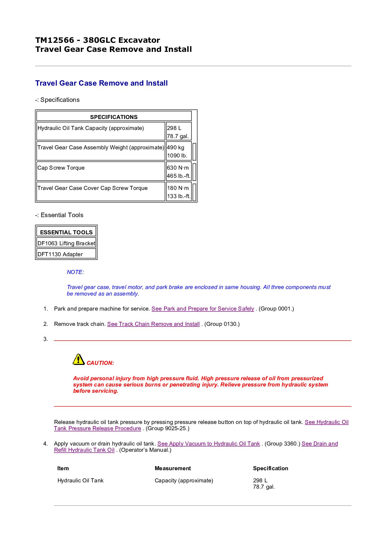
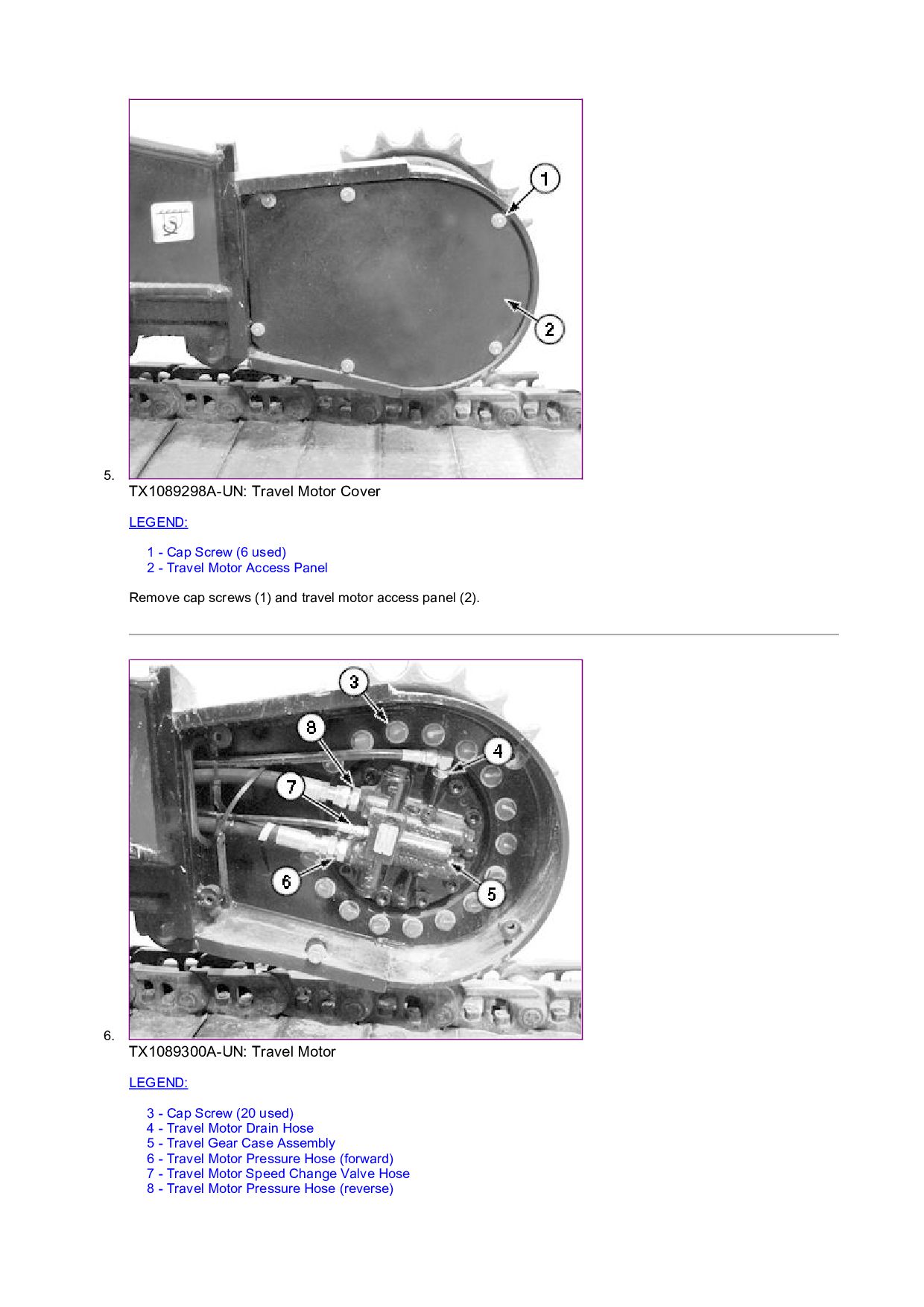
Travel Gear Case Remove and Install -: Specifications -: Essential Tools NOTE: Travel gear case, travel motor, and park brake are enclosed in same housing. All three components must be removed as an assembly. 1. Park and prepare machine for service. See Park and Prepare for Service Safely . (Group 0001.) 2. Remove track chain. See Track Chain Remove and Install . (Group 0130.) 3. CAUTION: Avoid personal injury from high pressure fluid. High pressure release of oil from pressurized system can cause serious burns or penetrating injury. Relieve pressure from hydraulic system before servicing. Release hydraulic oil tank pressure by pressing pressure release button on top of hydraulic oil tank. See Hydraulic Oil Tank Pressure Release Procedure . (Group 9025-25.) 4. Apply vacuum or drain hydraulic oil tank. See Apply Vacuum to Hydraulic Oil Tank . (Group 3360.) See Drain and Refill Hydraulic Tank Oil . (Operator’s Manual.) SPECIFICATIONS Hydraulic Oil Tank Capacity (approximate) 298 L 78.7 gal. Travel Gear Case Assembly Weight (approximate) 490 kg 1090 lb. Cap Screw Torque 630 N·m 465 lb.-ft. Travel Gear Case Cover Cap Screw Torque 180 N·m 133 lb.-ft. ESSENTIAL TOOLS DF1063 Lifting Bracket DFT1130 Adapter Item Measurement Specification Hydraulic Oil Tank Capacity (approximate) 298 L 78.7 gal.
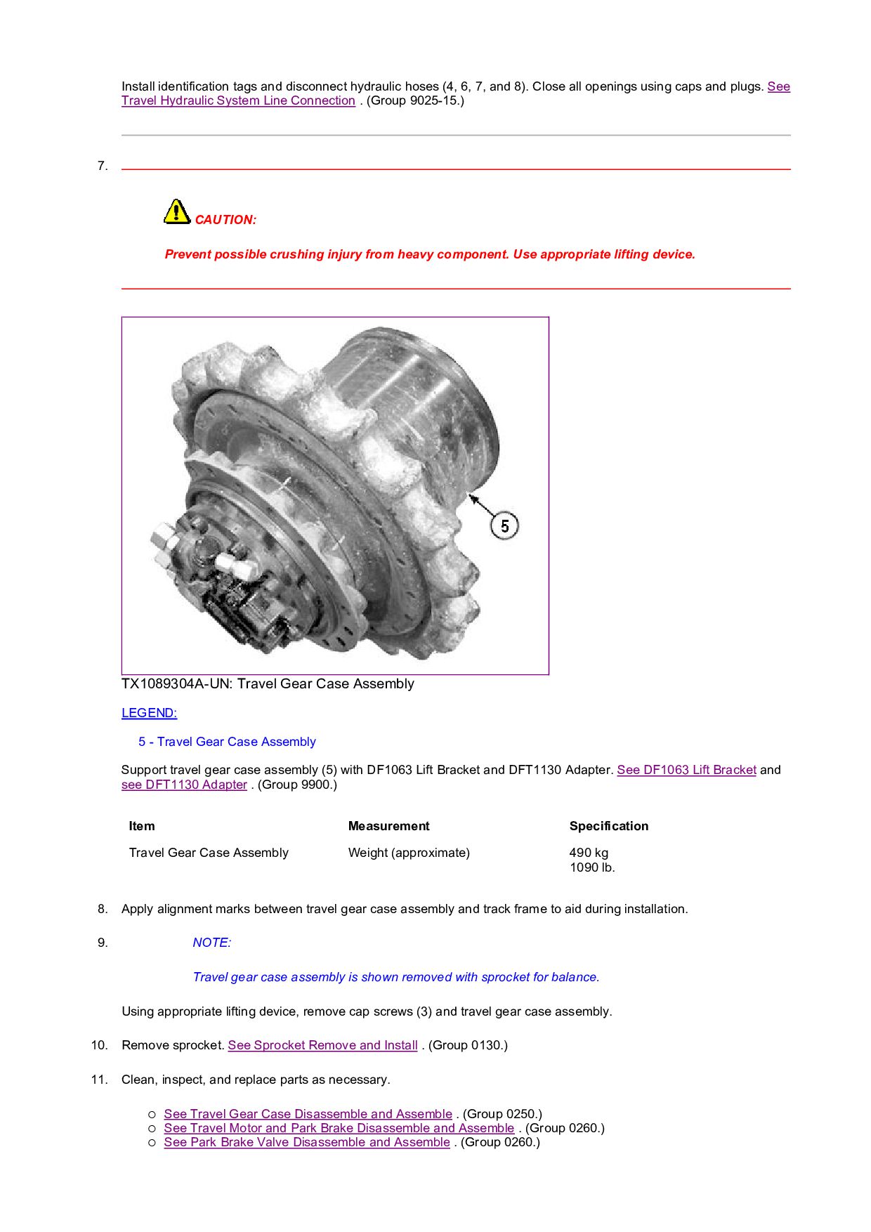
and 8). Close all openings using caps and plugs. See Travel Hydraulic System Line Connection . (Group 9025-15.) 7. CAUTION: Prevent possible crushing injury from heavy component. Use appropriate lifting device. TX1089304A-UN: Travel Gear Case Assembly LEGEND: 5 - Travel Gear Case Assembly Support travel gear case assembly (5) with DF1063 Lift Bracket and DFT1130 Adapter. See DF1063 Lift Bracket and see DFT1130 Adapter . (Group 9900.) 8. Apply alignment marks between travel gear case assembly and track frame to aid during installation. 9. NOTE: Travel gear case assembly is shown removed with sprocket for balance. Using appropriate lifting device, remove cap screws (3) and travel gear case assembly. 10. Remove sprocket. See Sprocket Remove and Install . (Group 0130.) 11. Clean, inspect, and replace parts as necessary. See Travel Gear Case Disassemble and Assemble . (Group 0250.) See Travel Motor and Park Brake Disassemble and Assemble . (Group 0260.) See Park Brake Valve Disassemble and Assemble . (Group 0260.) Item Measurement Specification Travel Gear Case Assembly Weight (approximate) 490 kg 1090 lb.
0130.) 13. CAUTION: Prevent possible crushing injury from heavy component. Use appropriate lifting device. Using appropriate lifting device, install travel gear case assembly. 14. Align marks on travel gear case assembly to mark on track frame. Install cap screws and tighten to specification. 15. NOTE: Travel motor drain hose (4) will remain capped and plugged until travel motor start-up procedure is performed. Connect hydraulic hoses (6, 7, and 8). See Travel Hydraulic System Line Connection . (Group 9025-15.) 16. Remove vacuum or fill hydraulic oil tank. See Apply Vacuum to Hydraulic Oil Tank . (Group 3360.) See Drain and Refill Hydraulic Tank Oil . (Operator’s Manual.) 17. Perform travel motor start-up procedure and connect travel motor drain hose (4). See Travel Motor and Park Brake Start-Up Procedure . (Group 0260.) 18. IMPORTANT: Hydraulic pumps will be damaged if not filled with oil before starting. Procedure must be performed to fill pump housings whenever oil has been drained from pumps or hydraulic oil tank. If hydraulic oil tank was drained, perform pump start-up procedure. See Pump 1 and 2 Start-Up Procedure . (Group 3360.) 19. Install track chain. See Track Chain Remove and Install . (Group 0130.) 20. Operate machine and check for leaks. 21. Install travel motor access panel and cap screws. Tighten to specification. Item Measurement Specification Travel Gear Case Assembly Weight (approximate) 490 kg 1090 lb. Item Measurement Specification Cap Screw Torque 630 N·m 465 lb.-ft. Item Measurement Specification Hydraulic Oil Tank Capacity (approximate) 298 L 78.7 gal. Item Measurement Specification Travel Gear Case Cover Cap Screw Torque 180 N·m 133 lb.-ft.
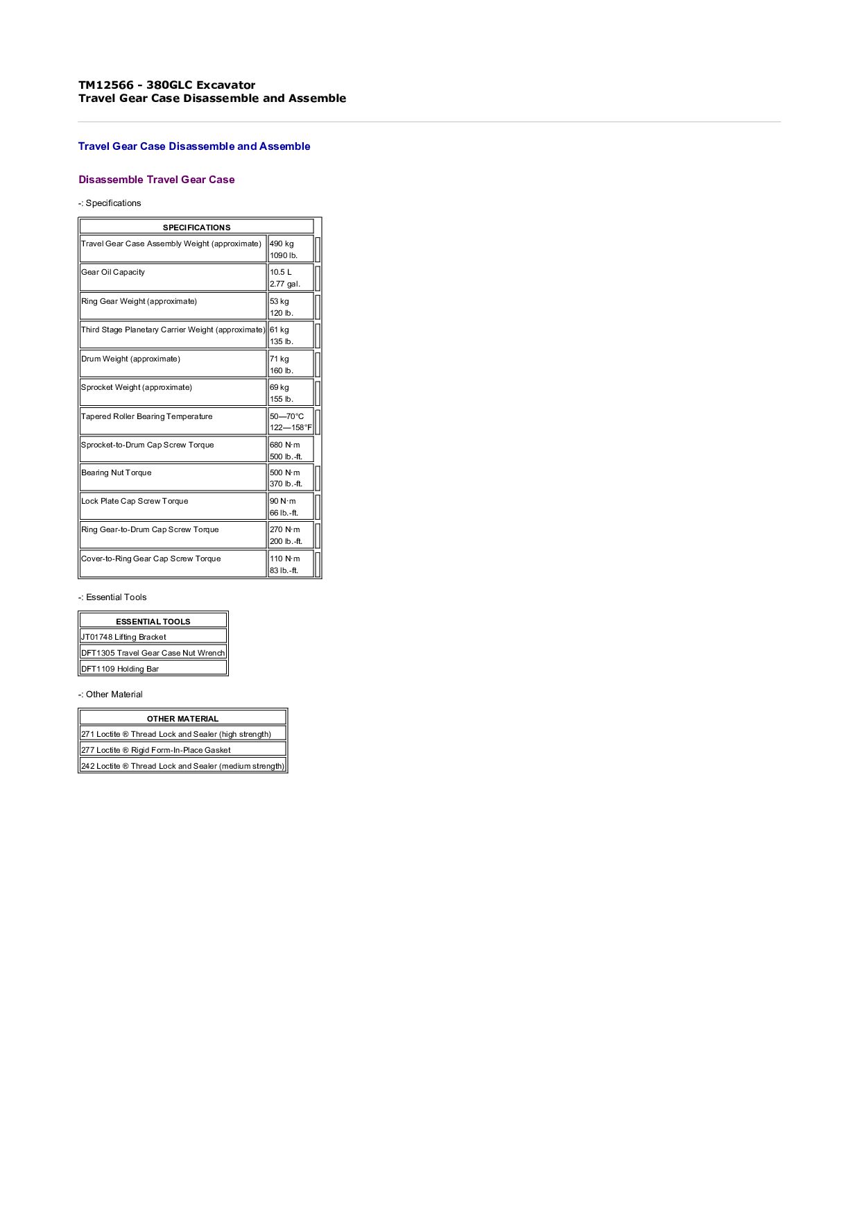
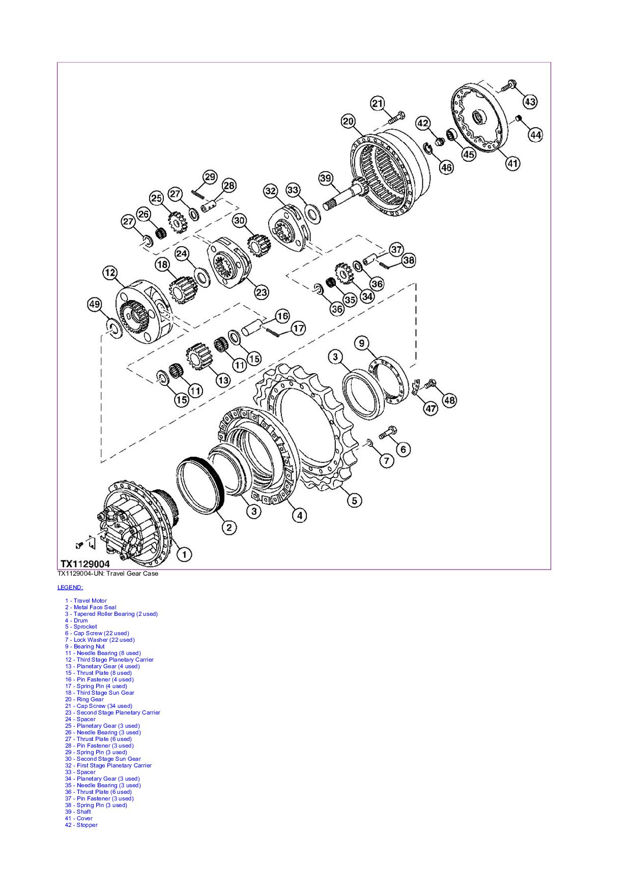
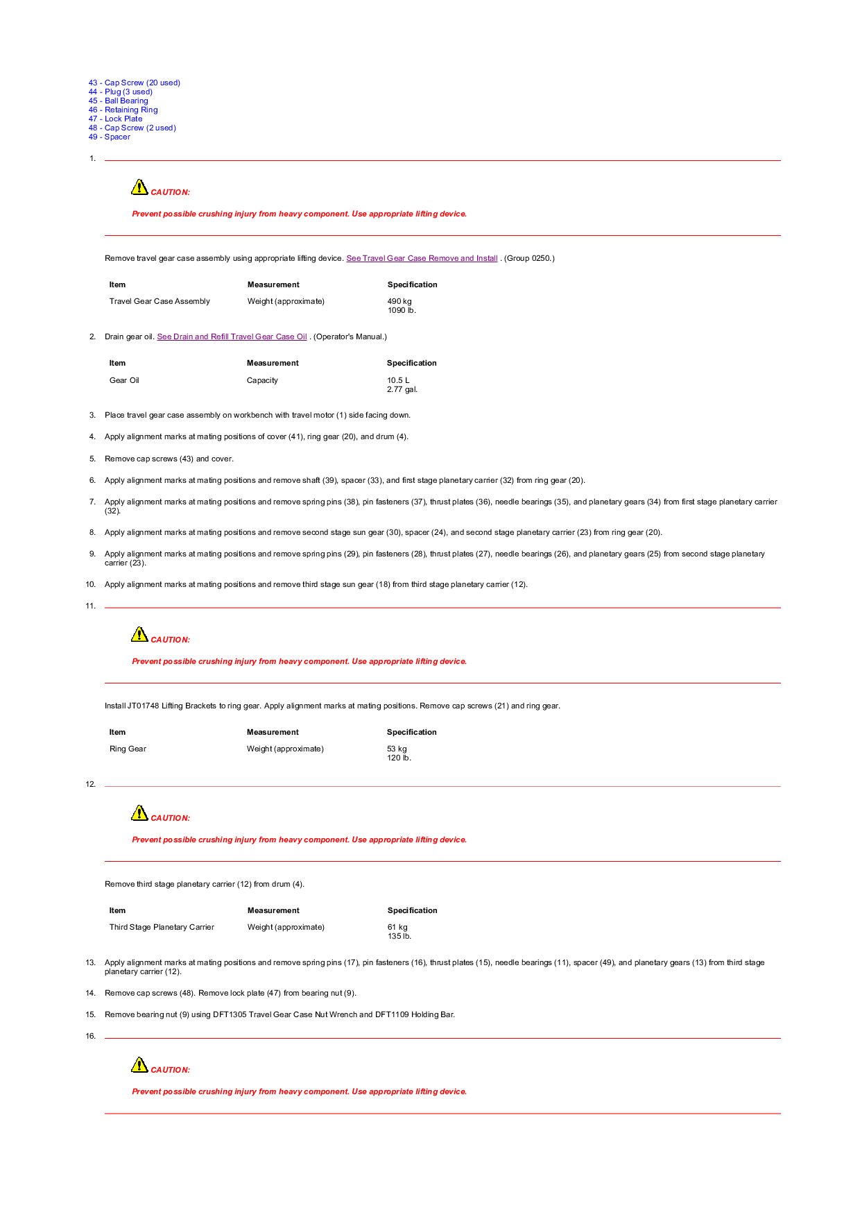
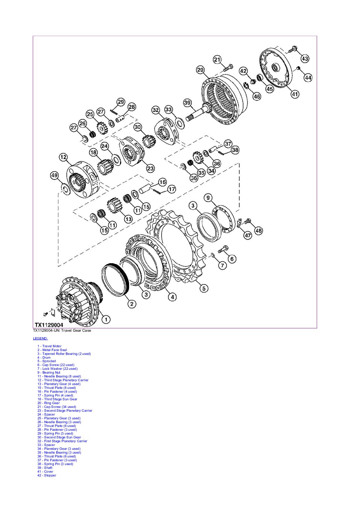
used) 45 - Ball Bearing 46 - Retaining Ring 47 - Lock Plate 48 - Cap Screw (2 used) 49 - Spacer 1. CAUTION: Prevent possible crushing injury from heavy component. Use appropriate lifting device. Remove travel gear case assembly using appropriate lifting device. See Travel Gear Case Remove and Install . (Group 0250.) 2. Drain gear oil. See Drain and Refill Travel Gear Case Oil . (Operator's Manual.) 3. Place travel gear case assembly on workbench with travel motor (1) side facing down. 4. Apply alignment marks at mating positions of cover (41), ring gear (20), and drum (4). 5. Remove cap screws (43) and cover. 6. Apply alignment marks at mating positions and remove shaft (39), spacer (33), and first stage planetary carrier (32) from ring gear (20). 7. Apply alignment marks at mating positions and remove spring pins (38), pin fasteners (37), thrust plates (36), needle bearings (35), and planetary gears (34) from first stage planetary carrier (32). 8. Apply alignment marks at mating positions and remove second stage sun gear (30), spacer (24), and second stage planetary carrier (23) from ring gear (20). 9. Apply alignment marks at mating positions and remove spring pins (29), pin fasteners (28), thrust plates (27), needle bearings (26), and planetary gears (25) from second stage planetary carrier (23). 10. Apply alignment marks at mating positions and remove third stage sun gear (18) from third stage planetary carrier (12). 11. CAUTION: Prevent possible crushing injury from heavy component. Use appropriate lifting device. Install JT01748 Lifting Brackets to ring gear. Apply alignment marks at mating positions. Remove cap screws (21) and ring gear. 12. CAUTION: Prevent possible crushing injury from heavy component. Use appropriate lifting device. Remove third stage planetary carrier (12) from drum (4). 13. Apply alignment marks at mating positions and remove spring pins (17), pin fasteners (16), thrust plates (15), needle bearings (11), spacer (49), and planetary gears (13) from third stage planetary carrier (12). 14. Remove cap screws (48). Remove lock plate (47) from bearing nut (9). 15. Remove bearing nut (9) using DFT1305 Travel Gear Case Nut Wrench and DFT1109 Holding Bar. 16. CAUTION: Prevent possible crushing injury from heavy component. Use appropriate lifting device. Item Measurement Specification Travel Gear Case Assembly Weight (approximate) 490 kg 1090 lb. Item Measurement Specification Gear Oil Capacity 10.5 L 2.77 gal. Item Measurement Specification Ring Gear Weight (approximate) 53 kg 120 lb. Item Measurement Specification Third Stage Planetary Carrier Weight (approximate) 61 kg 135 lb.
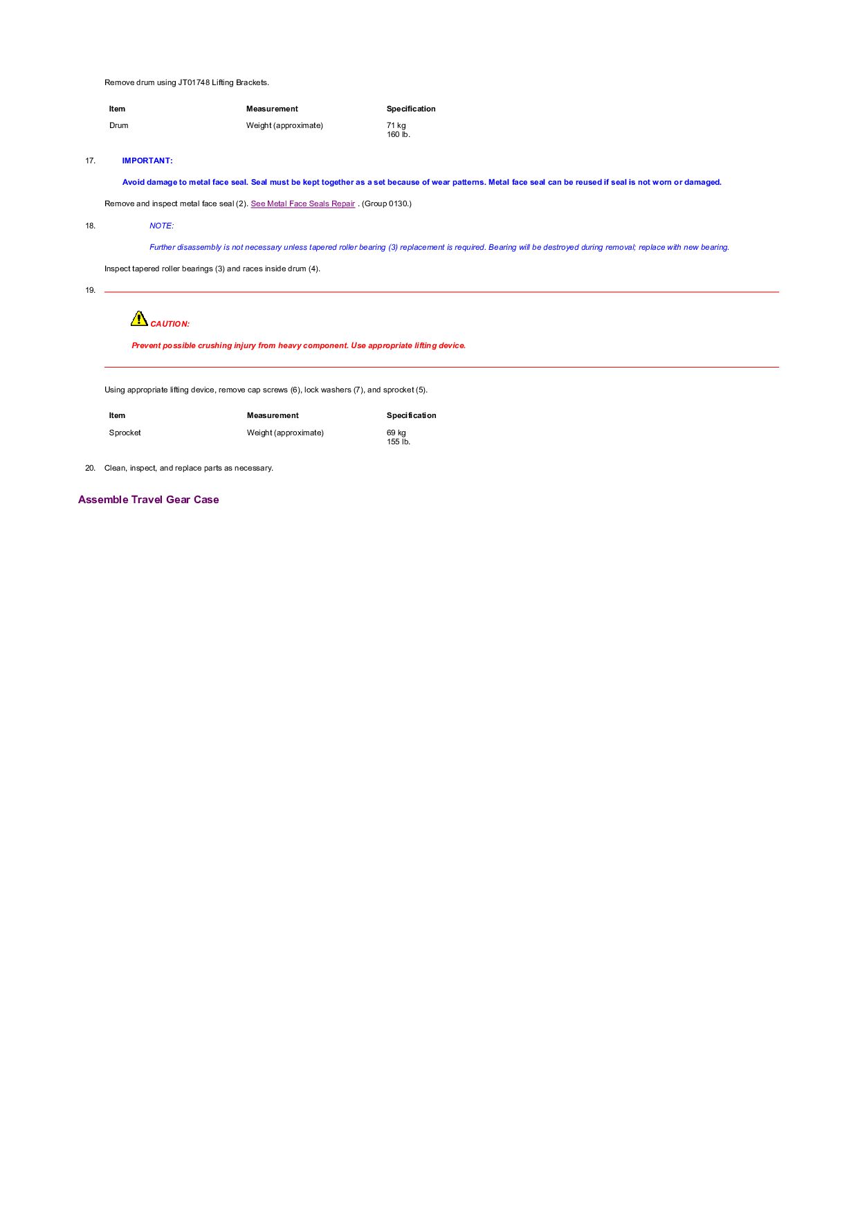
to metal face seal. Seal must be kept together as a set because of wear patterns. Metal face seal can be reused if seal is not worn or damaged. Remove and inspect metal face seal (2). See Metal Face Seals Repair . (Group 0130.) 18. NOTE: Further disassembly is not necessary unless tapered roller bearing (3) replacement is required. Bearing will be destroyed during removal; replace with new bearing. Inspect tapered roller bearings (3) and races inside drum (4). 19. CAUTION: Prevent possible crushing injury from heavy component. Use appropriate lifting device. Using appropriate lifting device, remove cap screws (6), lock washers (7), and sprocket (5). 20. Clean, inspect, and replace parts as necessary. Assemble Travel Gear Case Item Measurement Specification Drum Weight (approximate) 71 kg 160 lb. Item Measurement Specification Sprocket Weight (approximate) 69 kg 155 lb.
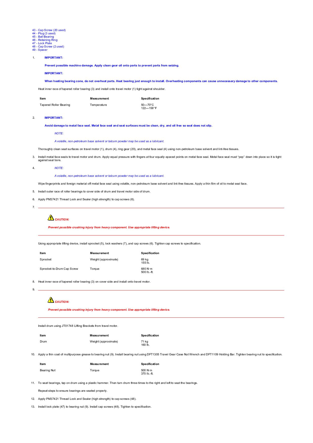
used) 45 - Ball Bearing 46 - Retaining Ring 47 - Lock Plate 48 - Cap Screw (2 used) 49 - Spacer 1. IMPORTANT: Prevent possible machine damage. Apply clean gear oil onto parts to prevent parts from seizing. IMPORTANT: When heating bearing cone, do not overheat parts. Heat bearing just enough to install. Overheating components can cause unnecessary damage to other components. Heat inner race of tapered roller bearing (3) and install onto travel motor (1) tight against shoulder. 2. IMPORTANT: Avoid damage to metal face seal. Metal face seal and seat surfaces must be clean, dry, and oil free so seal does not slip. NOTE: A volatile, non-petroleum base solvent or talcum powder may be used as a lubricant. Thoroughly clean seat surfaces on travel motor (1), drum (4), ring gear (20), and metal face seal (4) using non-petroleum base solvent and lint-free tissues. 3. Install metal face seals to travel motor and drum. Apply equal pressure with fingers at four equally-spaced points on metal face seal. Metal face seal must “pop” down into place so it is tight against seal bore. 4. NOTE: A volatile, non-petroleum base solvent or talcum powder may be used as a lubricant. Wipe fingerprints and foreign material off metal face seal using volatile, non-petroleum base solvent and lint-free tissues. Apply a thin film of oil to metal seal face. 5. Install outer race of roller bearings to cover side of drum and travel motor side of drum. 6. Apply PM37421 Thread Lock and Sealer (high strength) to cap screws (6). 7. CAUTION: Prevent possible crushing injury from heavy component. Use appropriate lifting device. Using appropriate lifting device, install sprocket (5), lock washers (7), and cap screws (6). Tighten cap screws to specification. 8. Heat inner race of tapered roller bearing (3) on cover side and install onto travel motor. 9. CAUTION: Prevent possible crushing injury from heavy component. Use appropriate lifting device. Install drum using JT01748 Lifting Brackets from travel motor. 10. Apply a thin coat of multipurpose grease to bearing nut (9). Install bearing nut using DFT1305 Travel Gear Case Nut Wrench and DFT1109 Holding Bar. Tighten bearing nut to specification. 11. To seat bearings, tap on drum using a plastic hammer. Then turn drum three times to the right and left to seat the bearings. Repeat steps to ensure bearings are seated properly. 12. Apply PM37421 Thread Lock and Sealer (high strength) to cap screws (48). 13. Install lock plate (47) to bearing nut (9). Install cap screws (48). Tighten to specification. Item Measurement Specification Tapered Roller Bearing Temperature 50—70°C 122—158°F Item Measurement Specification Sprocket Weight (approximate) 69 kg 155 lb. Sprocket-to-Drum Cap Screw Torque 680 N·m 500 lb.-ft. Item Measurement Specification Drum Weight (approximate) 71 kg 160 lb. Item Measurement Specification Bearing Nut Torque 500 N·m 370 lb.-ft.
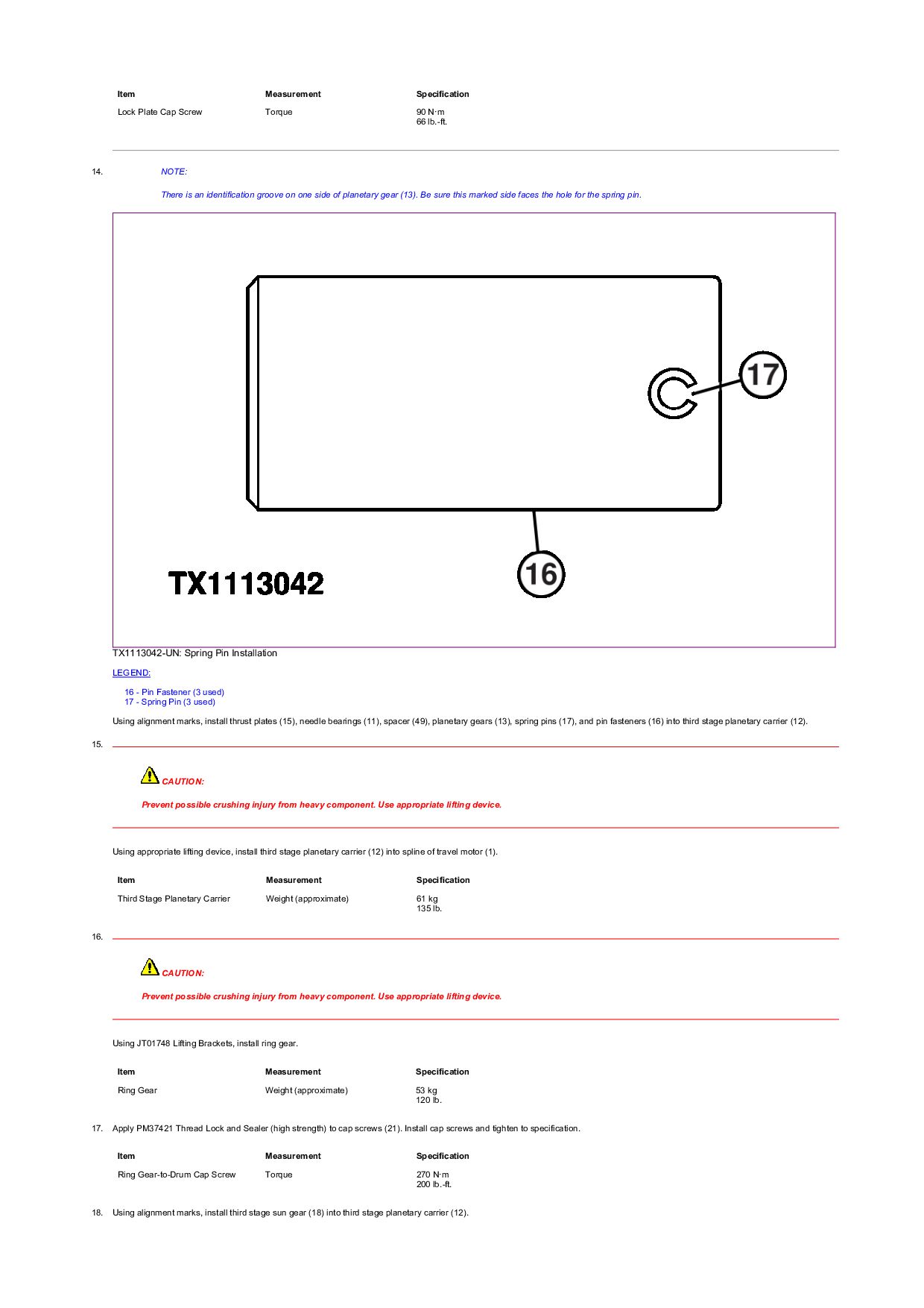
of planetary gear (13). Be sure this marked side faces the hole for the spring pin. TX1113042-UN: Spring Pin Installation LEGEND: 16 - Pin Fastener (3 used) 17 - Spring Pin (3 used) Using alignment marks, install thrust plates (15), needle bearings (11), spacer (49), planetary gears (13), spring pins (17), and pin fasteners (16) into third stage planetary carrier (12). 15. CAUTION: Prevent possible crushing injury from heavy component. Use appropriate lifting device. Using appropriate lifting device, install third stage planetary carrier (12) into spline of travel motor (1). 16. CAUTION: Prevent possible crushing injury from heavy component. Use appropriate lifting device. Using JT01748 Lifting Brackets, install ring gear. 17. Apply PM37421 Thread Lock and Sealer (high strength) to cap screws (21). Install cap screws and tighten to specification. 18. Using alignment marks, install third stage sun gear (18) into third stage planetary carrier (12). Item Measurement Specification Lock Plate Cap Screw Torque 90 N·m 66 lb.-ft. Item Measurement Specification Third Stage Planetary Carrier Weight (approximate) 61 kg 135 lb. Item Measurement Specification Ring Gear Weight (approximate) 53 kg 120 lb. Item Measurement Specification Ring Gear-to-Drum Cap Screw Torque 270 N·m 200 lb.-ft.
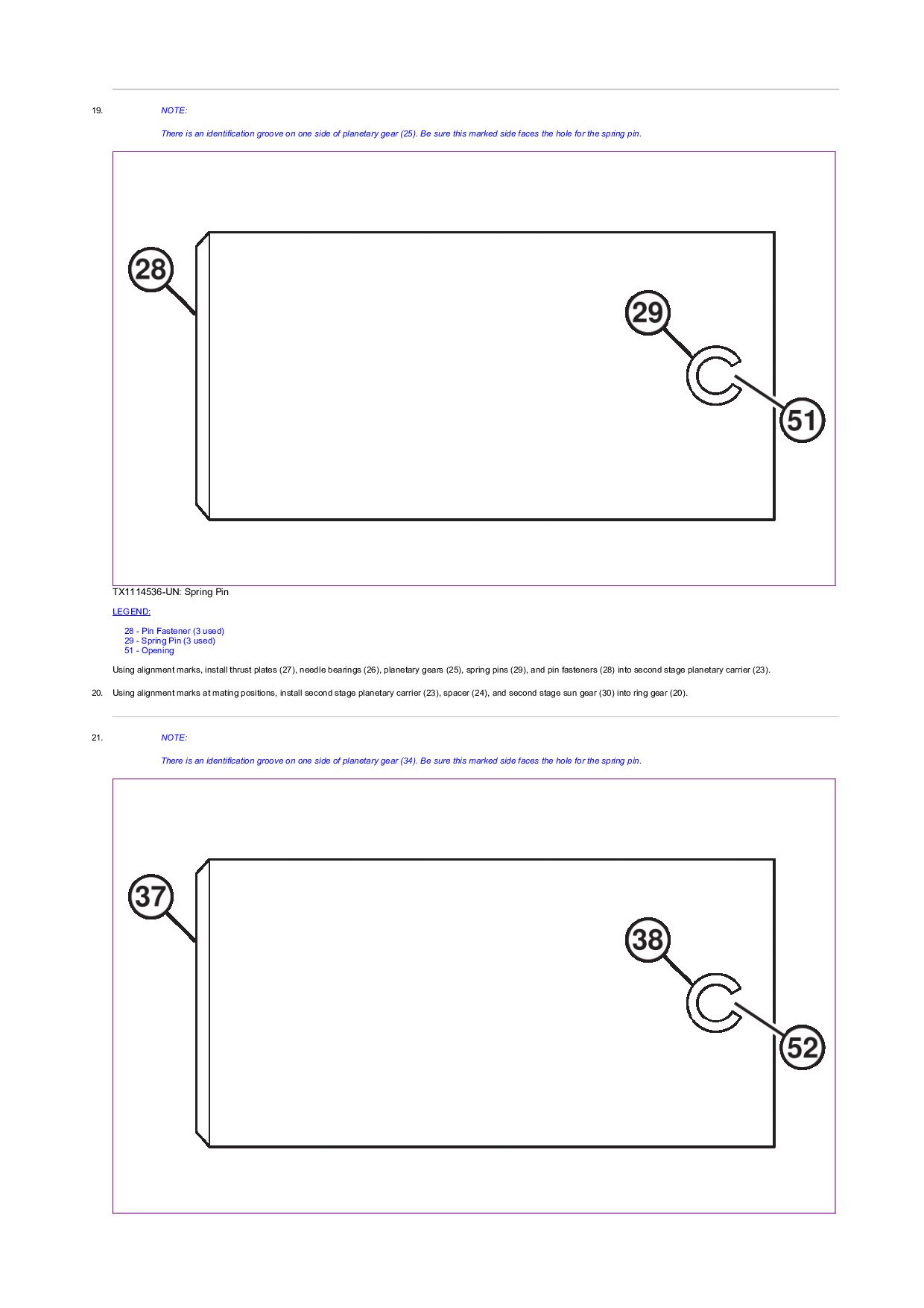
of planetary gear (25). Be sure this marked side faces the hole for the spring pin. TX1114536-UN: Spring Pin LEGEND: 28 - Pin Fastener (3 used) 29 - Spring Pin (3 used) 51 - Opening Using alignment marks, install thrust plates (27), needle bearings (26), planetary gears (25), spring pins (29), and pin fasteners (28) into second stage planetary carrier (23). 20. Using alignment marks at mating positions, install second stage planetary carrier (23), spacer (24), and second stage sun gear (30) into ring gear (20). 21. NOTE: There is an identification groove on one side of planetary gear (34). Be sure this marked side faces the hole for the spring pin.
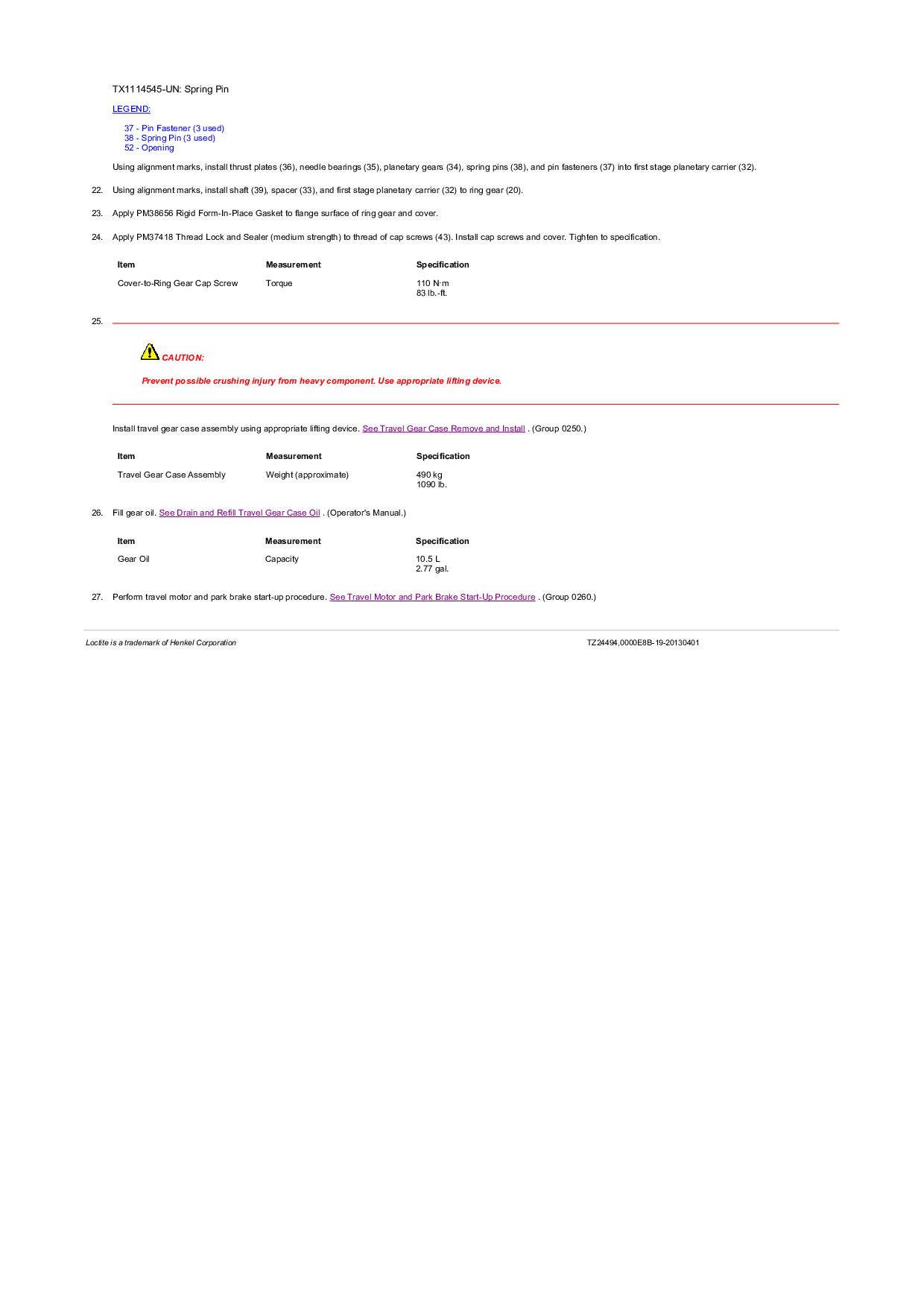
38 - Spring Pin (3 used) 52 - Opening Using alignment marks, install thrust plates (36), needle bearings (35), planetary gears (34), spring pins (38), and pin fasteners (37) into first stage planetary carrier (32). 22. Using alignment marks, install shaft (39), spacer (33), and first stage planetary carrier (32) to ring gear (20). 23. Apply PM38656 Rigid Form-In-Place Gasket to flange surface of ring gear and cover. 24. Apply PM37418 Thread Lock and Sealer (medium strength) to thread of cap screws (43). Install cap screws and cover. Tighten to specification. 25. CAUTION: Prevent possible crushing injury from heavy component. Use appropriate lifting device. Install travel gear case assembly using appropriate lifting device. See Travel Gear Case Remove and Install . (Group 0250.) 26. Fill gear oil. See Drain and Refill Travel Gear Case Oil . (Operator's Manual.) 27. Perform travel motor and park brake start-up procedure. See Travel Motor and Park Brake Start-Up Procedure . (Group 0260.) Item Measurement Specification Cover-to-Ring Gear Cap Screw Torque 110 N·m 83 lb.-ft. Item Measurement Specification Travel Gear Case Assembly Weight (approximate) 490 kg 1090 lb. Item Measurement Specification Gear Oil Capacity 10.5 L 2.77 gal. Loctite is a trademark of Henkel Corporation TZ24494,0000E8B-19-20130401
and Install Travel Motor and Park Brake Remove and Install NOTE: The travel gear case, travel motor, and park brake are enclosed in the same housing. All three components must be removed as an assembly. See Travel Gear Case Remove and Install . (Group 0250.) To access travel motor, travel gear case must be disassembled. See Travel Gear Case Disassemble and Assemble . (Group 0250.) TZ24494,0000E8C-19-20130319


 sxedcwrfvk
 csswizardry
 kristinabergwall1
 tammyeverts
 axbom
 mojombo
 dougneiner
 marketingsoph
 andyhume
 inesmontani
 katiecoart
 tanoku
 smashingmag