VCAP6.5-DCV, VCAP7/6-CMA, VCP7-CMA, VCP6*-* @tenthirtyam Mike Brown Senior SDDC Integration Architect, VMware, Inc. VCDX6-DCV, VCIX6-DCV, VCIX6-NV @vMikeBrown PBO1721BU #VMworld #PBO1721BU VMware Validated Design for Software-Defined Data Center: Technical Deep Dive
under development. • This overview of new technology represents no commitment from VMware to deliver these features in any generally available product. • Features are subject to change, and must not be included in contracts, purchase orders, or sales agreements of any kind. • Technical feasibility and market demand will affect final delivery. • Pricing and packaging for any new technologies or features discussed or presented have not been determined. Disclaimer 2
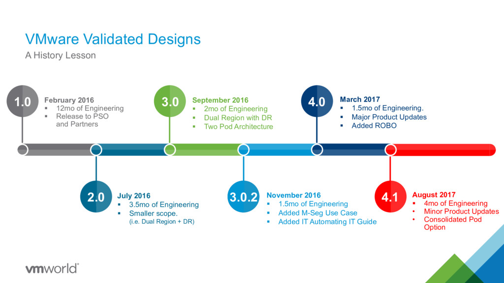
3.0.2 4.0 4.1 February 2016 § 12mo of Engineering § Release to PSO and Partners September 2016 § 2mo of Engineering § Dual Region with DR § Two Pod Architecture July 2016 § 3.5mo of Engineering § Smaller scope. (i.e. Dual Region + DR) November 2016 § 1.5mo of Engineering § Added M-Seg Use Case § Added IT Automating IT Guide March 2017 § 1.5mo of Engineering. § Major Product Updates § Added ROBO August 2017 § 4mo of Engineering • Minor Product Updates • Consolidated Pod Option
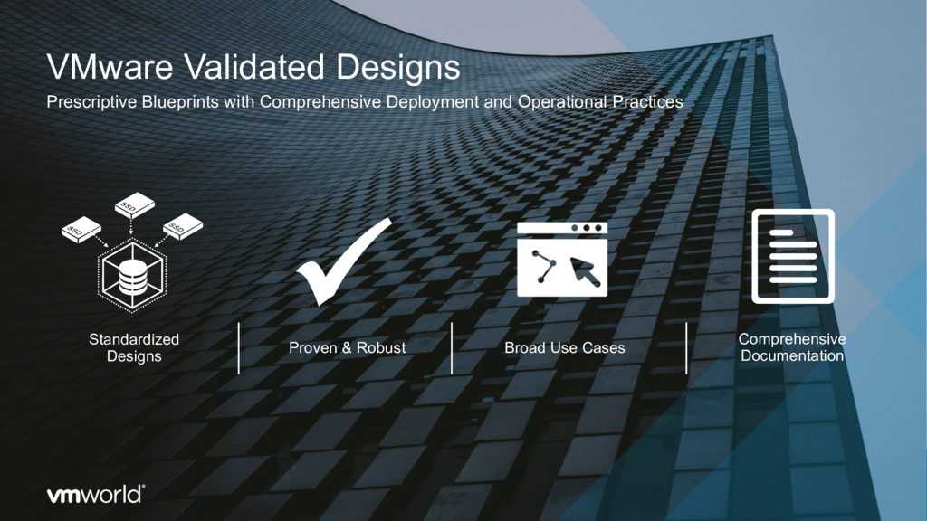
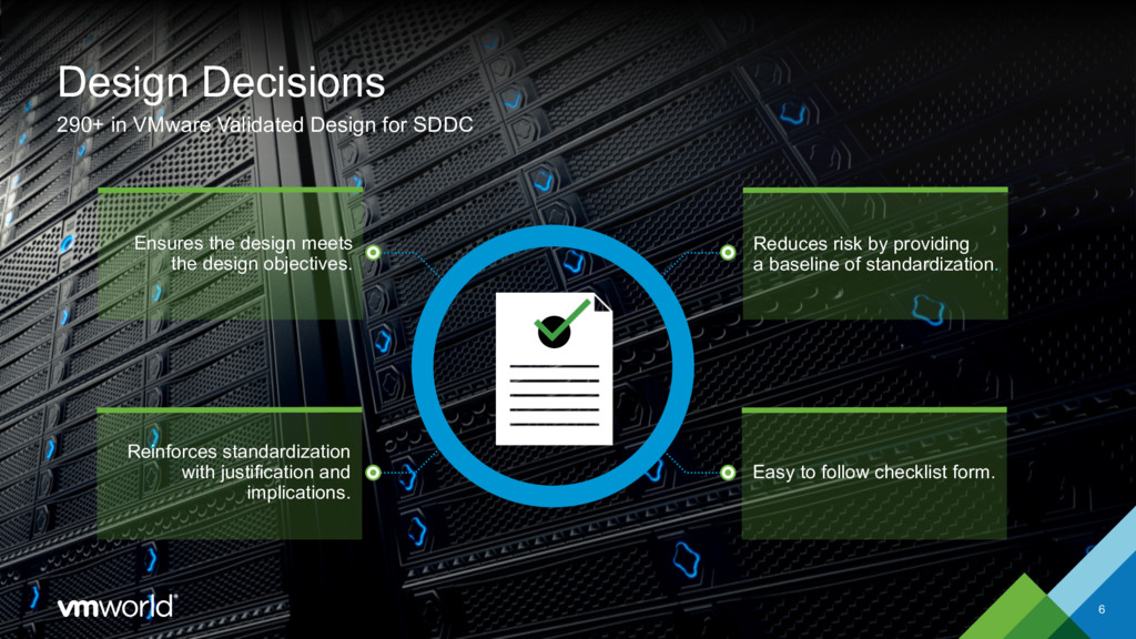
Reduces risk by providing a baseline of standardization. Ensures the design meets the design objectives. Reinforces standardization with justification and implications. Easy to follow checklist form.
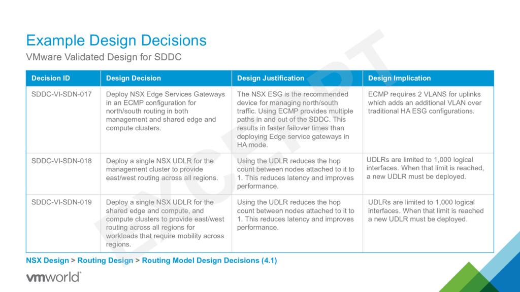
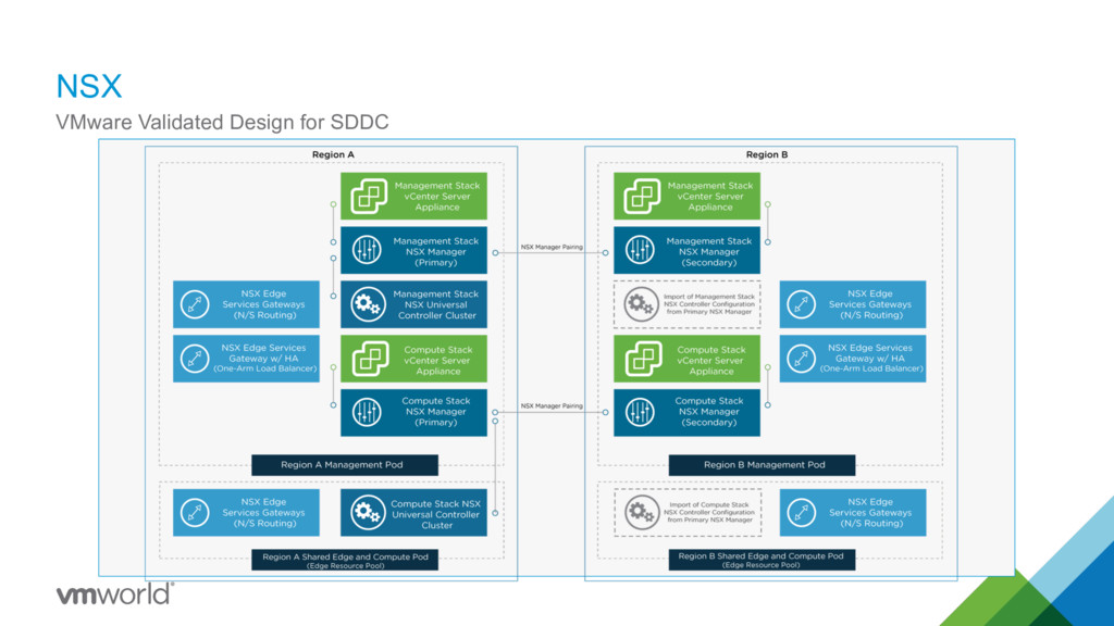
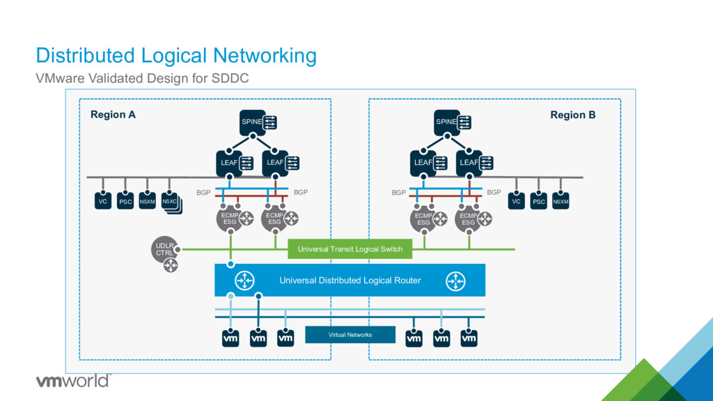
> Routing Design > Routing Model Design Decisions (4.1) Decision ID Design Decision Design Justification Design Implication SDDC-VI-SDN-017 Deploy NSX Edge Services Gateways in an ECMP configuration for north/south routing in both management and shared edge and compute clusters. The NSX ESG is the recommended device for managing north/south traffic. Using ECMP provides multiple paths in and out of the SDDC. This results in faster failover times than deploying Edge service gateways in HA mode. ECMP requires 2 VLANS for uplinks which adds an additional VLAN over traditional HA ESG configurations. SDDC-VI-SDN-018 Deploy a single NSX UDLR for the management cluster to provide east/west routing across all regions. Using the UDLR reduces the hop count between nodes attached to it to 1. This reduces latency and improves performance. UDLRs are limited to 1,000 logical interfaces. When that limit is reached, a new UDLR must be deployed. SDDC-VI-SDN-019 Deploy a single NSX UDLR for the shared edge and compute, and compute clusters to provide east/west routing across all regions for workloads that require mobility across regions. Using the UDLR reduces the hop count between nodes attached to it to 1. This reduces latency and improves performance. UDLRs are limited to 1,000 logical interfaces. When that limit is reached a new UDLR must be deployed.
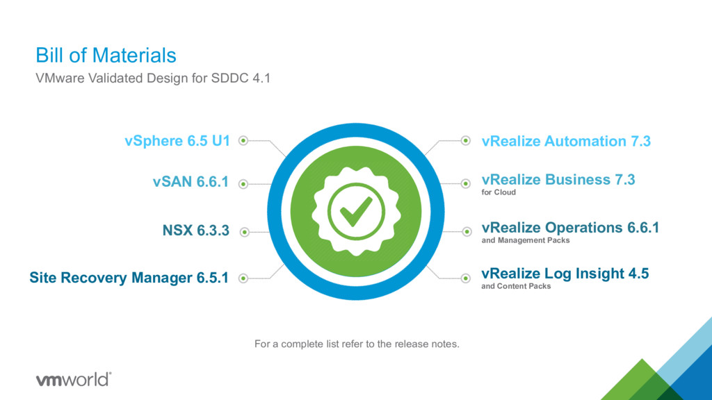
U1 vSAN 6.6.1 Site Recovery Manager 6.5.1 vRealize Log Insight 4.5 and Content Packs vRealize Operations 6.6.1 and Management Packs NSX 6.3.3 Bill of Materials VMware Validated Design for SDDC 4.1 For a complete list refer to the release notes.
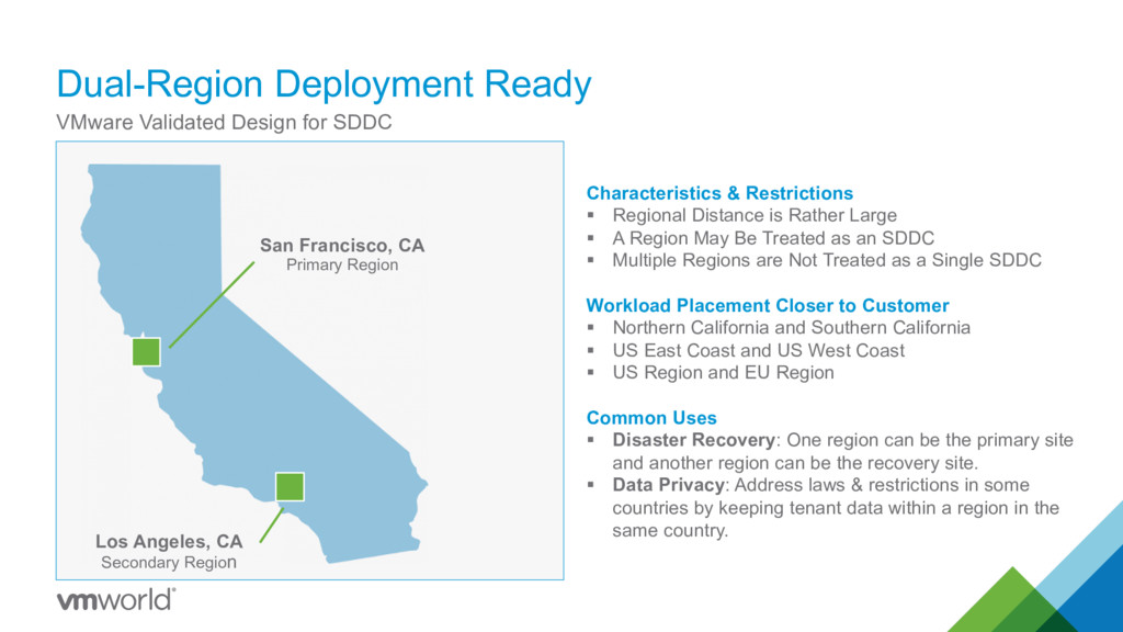
Restrictions § Regional Distance is Rather Large § A Region May Be Treated as an SDDC § Multiple Regions are Not Treated as a Single SDDC Workload Placement Closer to Customer § Northern California and Southern California § US East Coast and US West Coast § US Region and EU Region Common Uses § Disaster Recovery: One region can be the primary site and another region can be the recovery site. § Data Privacy: Address laws & restrictions in some countries by keeping tenant data within a region in the same country. San Francisco, CA Primary Region Los Angeles, CA Secondary Region
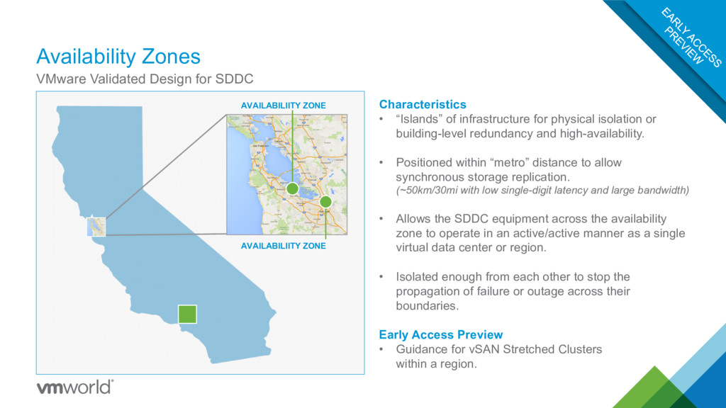
ZONE Characteristics • “Islands” of infrastructure for physical isolation or building-level redundancy and high-availability. • Positioned within “metro” distance to allow synchronous storage replication. (~50km/30mi with low single-digit latency and large bandwidth) • Allows the SDDC equipment across the availability zone to operate in an active/active manner as a single virtual data center or region. • Isolated enough from each other to stop the propagation of failure or outage across their boundaries. Early Access Preview • Guidance for vSAN Stretched Clusters within a region.
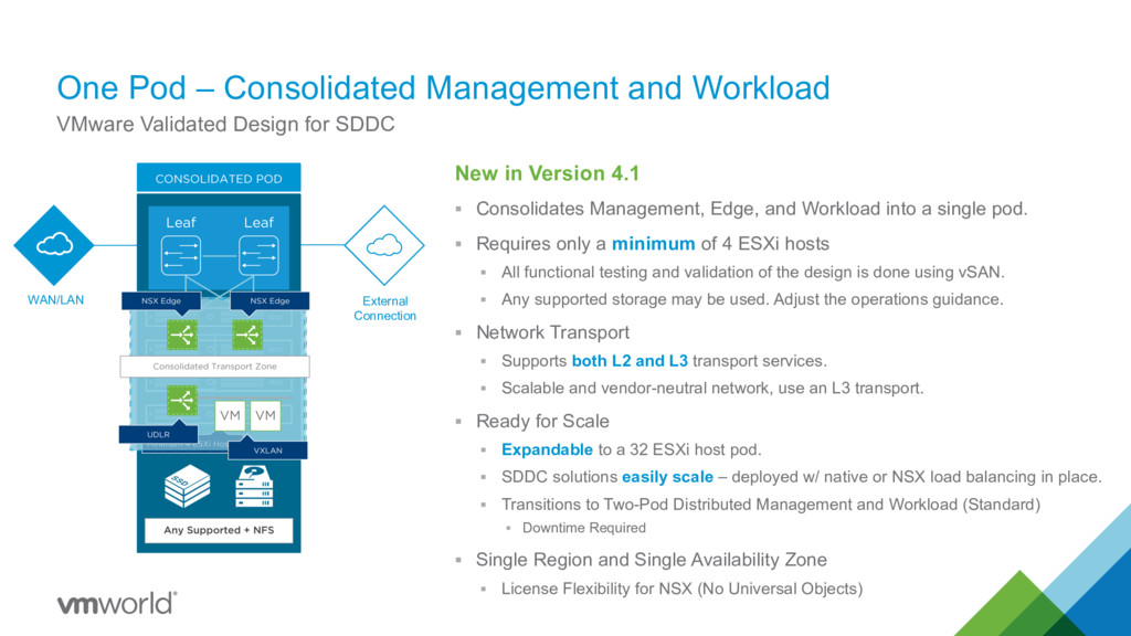
for SDDC New in Version 4.1 § Consolidates Management, Edge, and Workload into a single pod. § Requires only a minimum of 4 ESXi hosts § All functional testing and validation of the design is done using vSAN. § Any supported storage may be used. Adjust the operations guidance. § Network Transport § Supports both L2 and L3 transport services. § Scalable and vendor-neutral network, use an L3 transport. § Ready for Scale § Expandable to a 32 ESXi host pod. § SDDC solutions easily scale – deployed w/ native or NSX load balancing in place. § Transitions to Two-Pod Distributed Management and Workload (Standard) § Downtime Required § Single Region and Single Availability Zone § License Flexibility for NSX (No Universal Objects) External Connection WAN/LAN
/ Standard Architecture One-Pod / Consolidated Architecture Minimum Hosts 8 4 Management VMs 420 GB vRAM, 2TB VSAN, 6 TB NFS 50% - 70% less Recoverability Dual Region Single Region (DR to cloud) Scale (VMs) Up to 10,000 Up to 1,500 Churn Medium (up to 150/hr) Low (up to 50/hr) Availability 99% 95% Modularity Foundation Cloud Operations Cloud Management Foundation Cloud Operations Cloud Management Expansion options Additional Compute Pods (Up to 32 Hosts Each) Expand Pod to 32 Hosts or Grow to 2-Pod
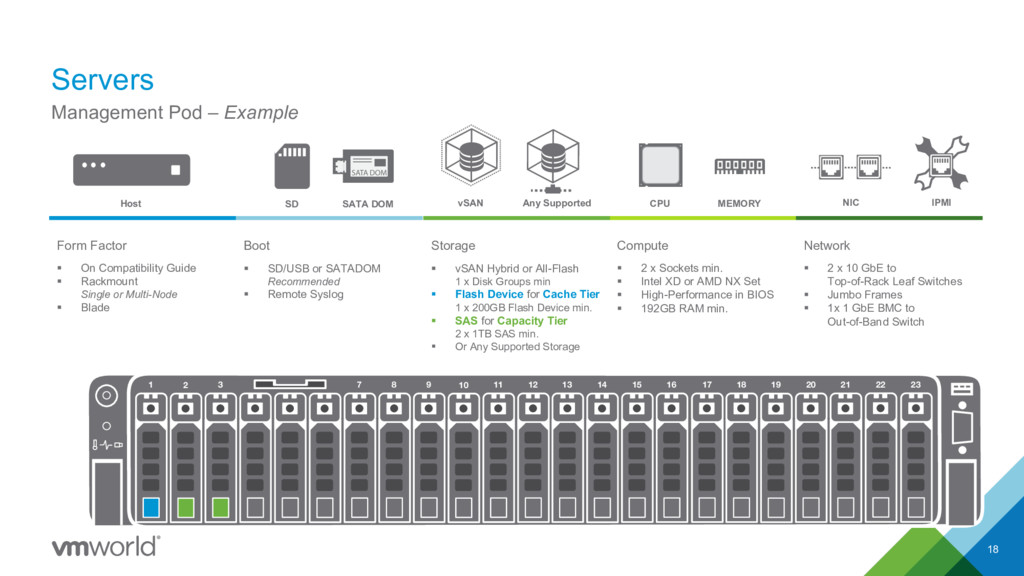
8 9 10 11 12 13 14 15 16 17 18 19 20 21 22 23 SD § SD/USB or SATADOM Recommended § Remote Syslog Boot § On Compatibility Guide § Rackmount Single or Multi-Node § Blade Form Factor § 2 x Sockets min. § Intel XD or AMD NX Set § High-Performance in BIOS § 192GB RAM min. Compute § 2 x 10 GbE to Top-of-Rack Leaf Switches § Jumbo Frames § 1x 1 GbE BMC to Out-of-Band Switch Network Host § vSAN Hybrid or All-Flash 1 x Disk Groups min § Flash Device for Cache Tier 1 x 200GB Flash Device min. § SAS for Capacity Tier 2 x 1TB SAS min. § Or Any Supported Storage Storage SATA DOM CPU MEMORY NIC IPMI Any Supported vSAN
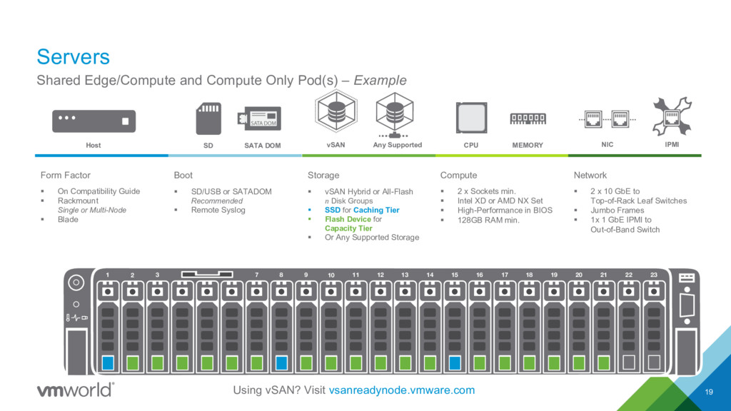
SD § SD/USB or SATADOM Recommended § Remote Syslog Boot § 2 x Sockets min. § Intel XD or AMD NX Set § High-Performance in BIOS § 128GB RAM min. Compute Host § vSAN Hybrid or All-Flash n Disk Groups § SSD for Caching Tier § Flash Device for Capacity Tier § Or Any Supported Storage Storage SATA DOM CPU MEMORY NIC IPMI § On Compatibility Guide § Rackmount Single or Multi-Node § Blade Form Factor Any Supported vSAN § 2 x 10 GbE to Top-of-Rack Leaf Switches § Jumbo Frames § 1x 1 GbE IPMI to Out-of-Band Switch Network 1 2 3 7 8 9 10 11 12 13 14 15 16 17 18 19 20 21 22 23 Using vSAN? Visit vsanreadynode.vmware.com
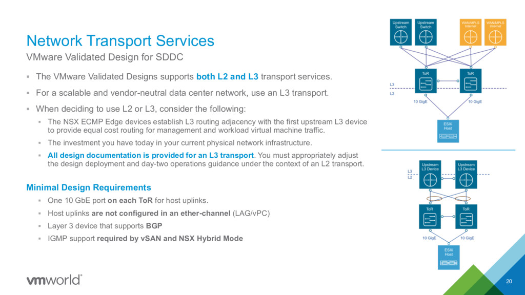
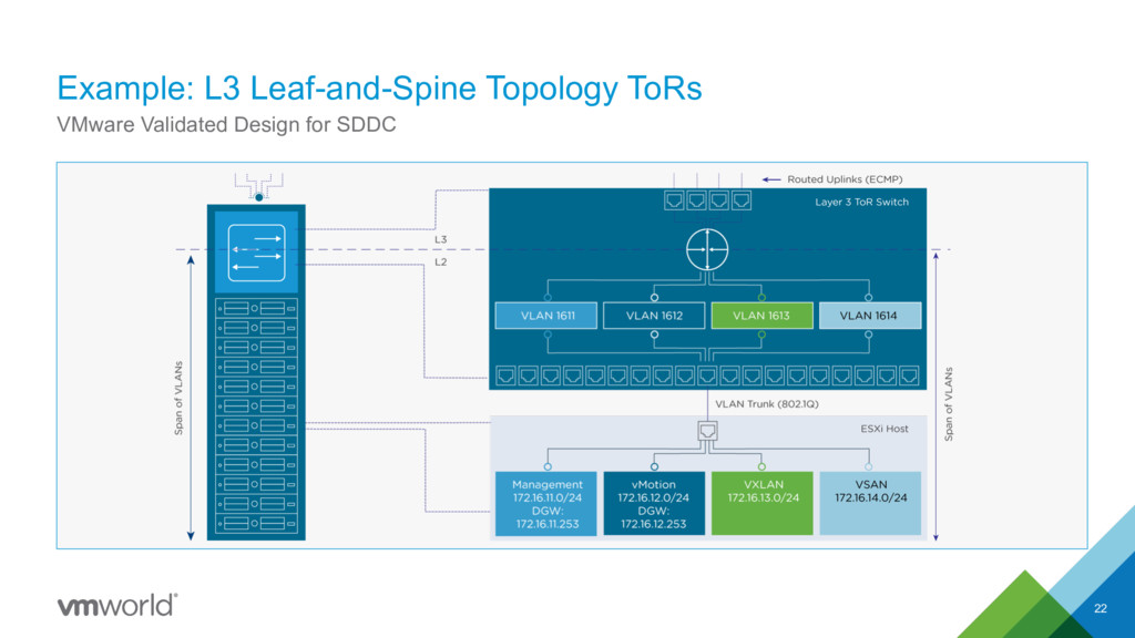
L2 and L3 transport services. § For a scalable and vendor-neutral data center network, use an L3 transport. § When deciding to use L2 or L3, consider the following: § The NSX ECMP Edge devices establish L3 routing adjacency with the first upstream L3 device to provide equal cost routing for management and workload virtual machine traffic. § The investment you have today in your current physical network infrastructure. § All design documentation is provided for an L3 transport. You must appropriately adjust the design deployment and day-two operations guidance under the context of an L2 transport. Minimal Design Requirements § One 10 GbE port on each ToR for host uplinks. § Host uplinks are not configured in an ether-channel (LAG/vPC) § Layer 3 device that supports BGP § IGMP support required by vSAN and NSX Hybrid Mode 20 VMware Validated Design for SDDC
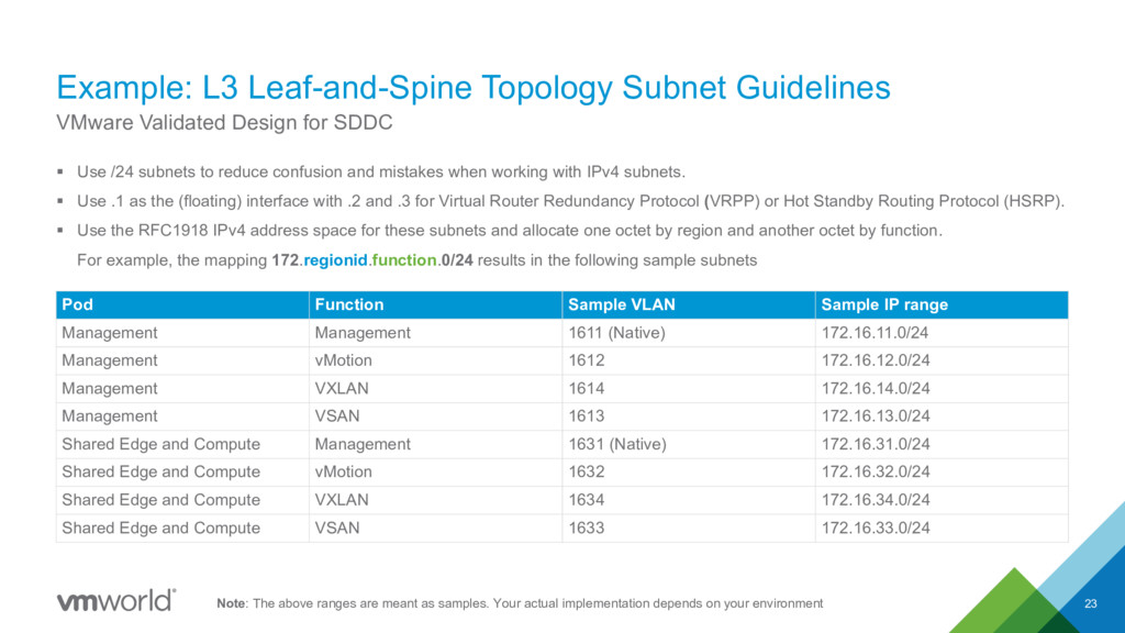
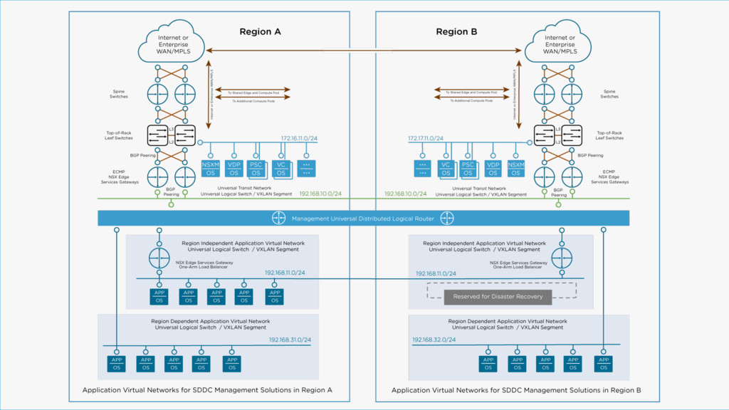
to reduce confusion and mistakes when working with IPv4 subnets. § Use .1 as the (floating) interface with .2 and .3 for Virtual Router Redundancy Protocol (VRPP) or Hot Standby Routing Protocol (HSRP). § Use the RFC1918 IPv4 address space for these subnets and allocate one octet by region and another octet by function. For example, the mapping 172.regionid.function.0/24 results in the following sample subnets 23 VMware Validated Design for SDDC Pod Function Sample VLAN Sample IP range Management Management 1611 (Native) 172.16.11.0/24 Management vMotion 1612 172.16.12.0/24 Management VXLAN 1614 172.16.14.0/24 Management VSAN 1613 172.16.13.0/24 Shared Edge and Compute Management 1631 (Native) 172.16.31.0/24 Shared Edge and Compute vMotion 1632 172.16.32.0/24 Shared Edge and Compute VXLAN 1634 172.16.34.0/24 Shared Edge and Compute VSAN 1633 172.16.33.0/24 Note: The above ranges are meant as samples. Your actual implementation depends on your environment
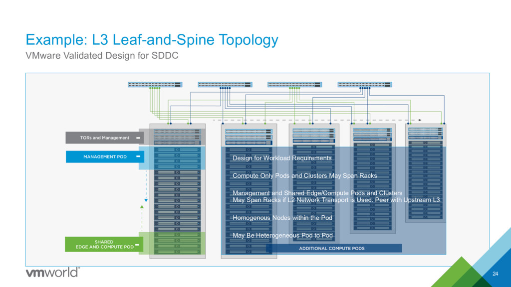
Design for Workload Requirements Compute Only Pods and Clusters May Span Racks Management and Shared Edge/Compute Pods and Clusters May Span Racks if L2 Network Transport is Used. Peer with Upstream L3. Homogenous Nodes within the Pod May Be Heterogeneous Pod to Pod
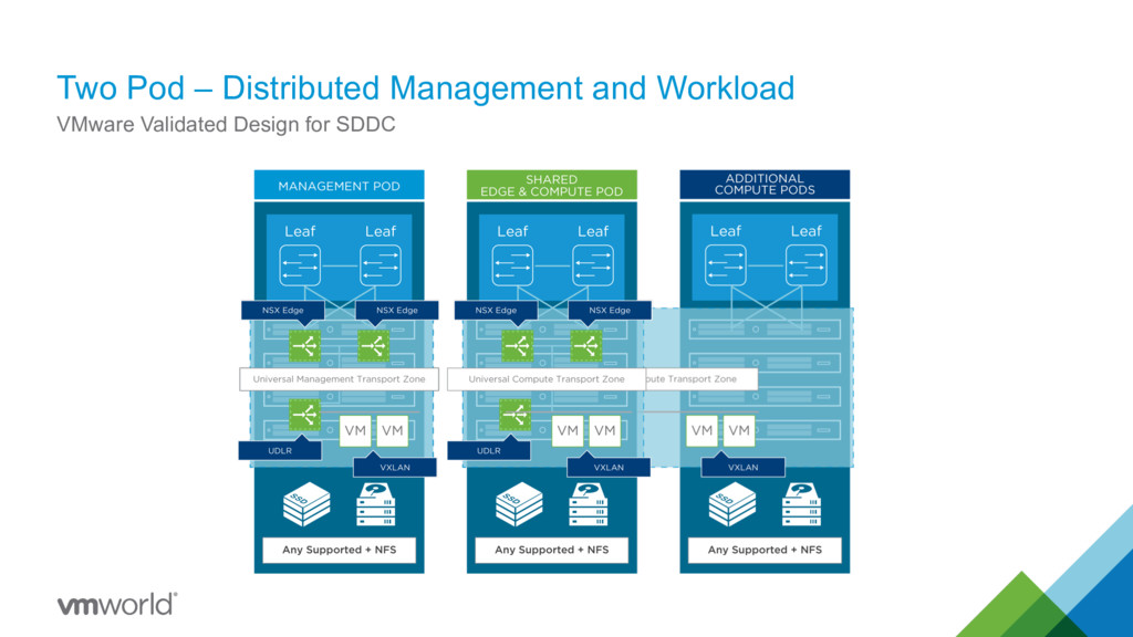
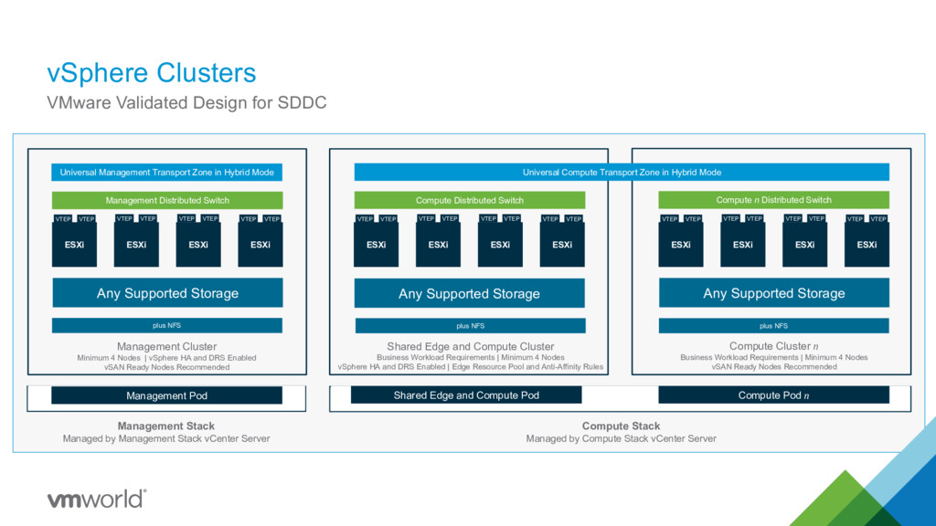
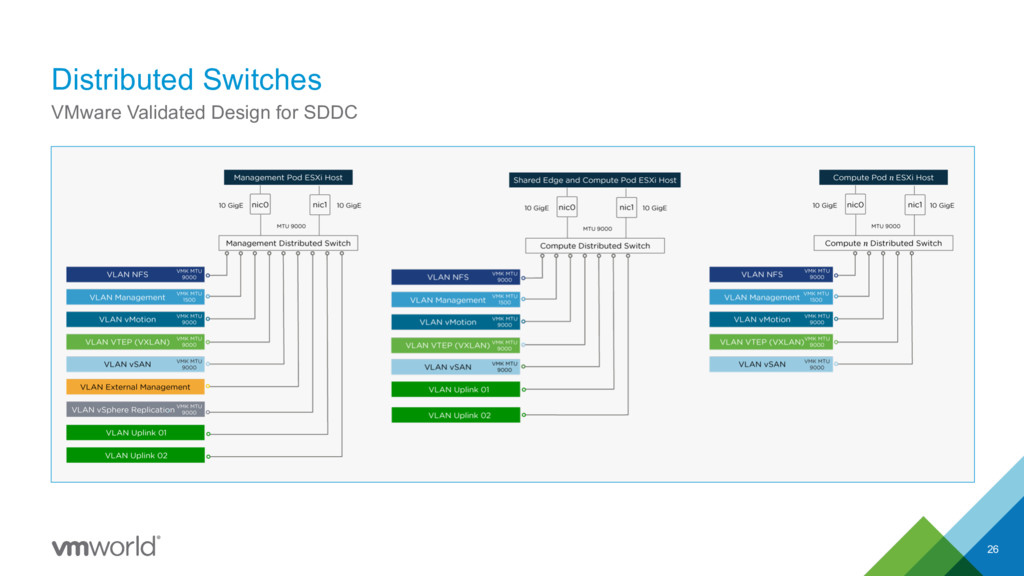
ESXi ESXi Management Distributed Switch Universal Management Transport Zone in Hybrid Mode Any Supported Storage plus NFS VTEP VTEP VTEP VTEP VTEP VTEP VTEP VTEP ESXi ESXi ESXi ESXi Compute Distributed Switch Any Supported Storage VTEP VTEP VTEP VTEP VTEP VTEP VTEP VTEP ESXi ESXi ESXi ESXi Compute n Distributed Switch Any Supported Storage VTEP VTEP VTEP VTEP VTEP VTEP VTEP VTEP Universal Compute Transport Zone in Hybrid Mode plus NFS Management Cluster Minimum 4 Nodes | vSphere HA and DRS Enabled vSAN Ready Nodes Recommended Shared Edge and Compute Cluster Business Workload Requirements | Minimum 4 Nodes vSphere HA and DRS Enabled | Edge Resource Pool and Anti-Affinity Rules Compute Cluster n Business Workload Requirements | Minimum 4 Nodes vSAN Ready Nodes Recommended Management Stack Managed by Management Stack vCenter Server Compute Stack Managed by Compute Stack vCenter Server Management Pod Shared Edge and Compute Pod Compute Pod n plus NFS
vSAN is Recommended for Management Pod Any Supported Storage for Shared Edge and Compute Pod Any Supported Storage for Compute Only Pod(s) Secondary Storage NFS for Backups NFS for Log Archives NFS for Content Library and Templates
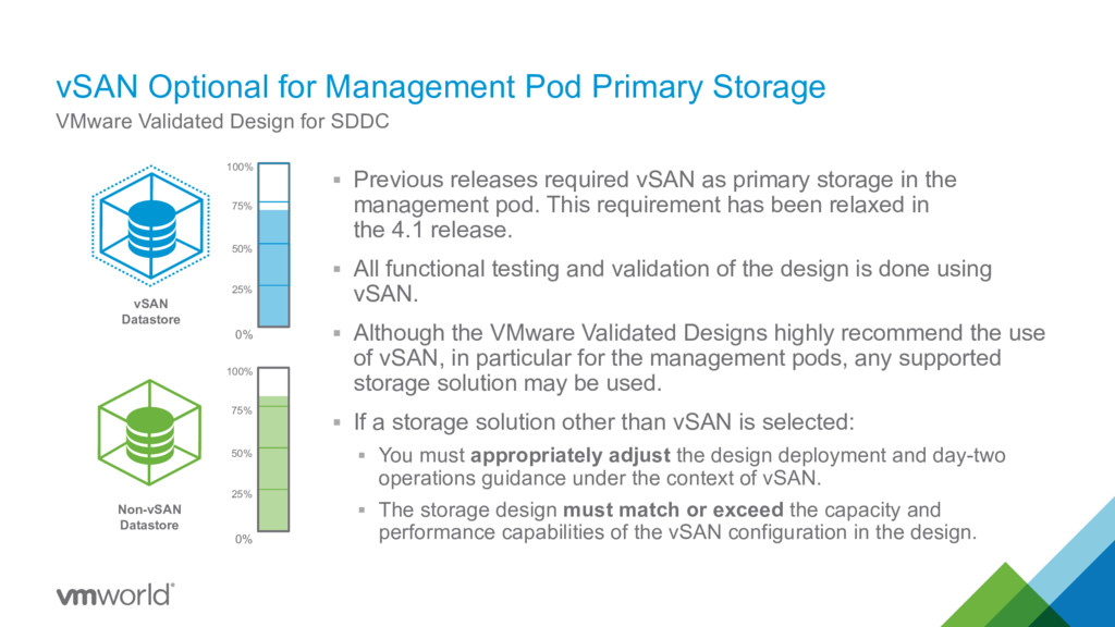
required vSAN as primary storage in the management pod. This requirement has been relaxed in the 4.1 release. § All functional testing and validation of the design is done using vSAN. § Although the VMware Validated Designs highly recommend the use of vSAN, in particular for the management pods, any supported storage solution may be used. § If a storage solution other than vSAN is selected: § You must appropriately adjust the design deployment and day-two operations guidance under the context of vSAN. § The storage design must match or exceed the capacity and performance capabilities of the vSAN configuration in the design. VMware Validated Design for SDDC 0% 50% 100% 25% 75% 0% 50% 100% 25% 75% vSAN Datastore Non-vSAN Datastore
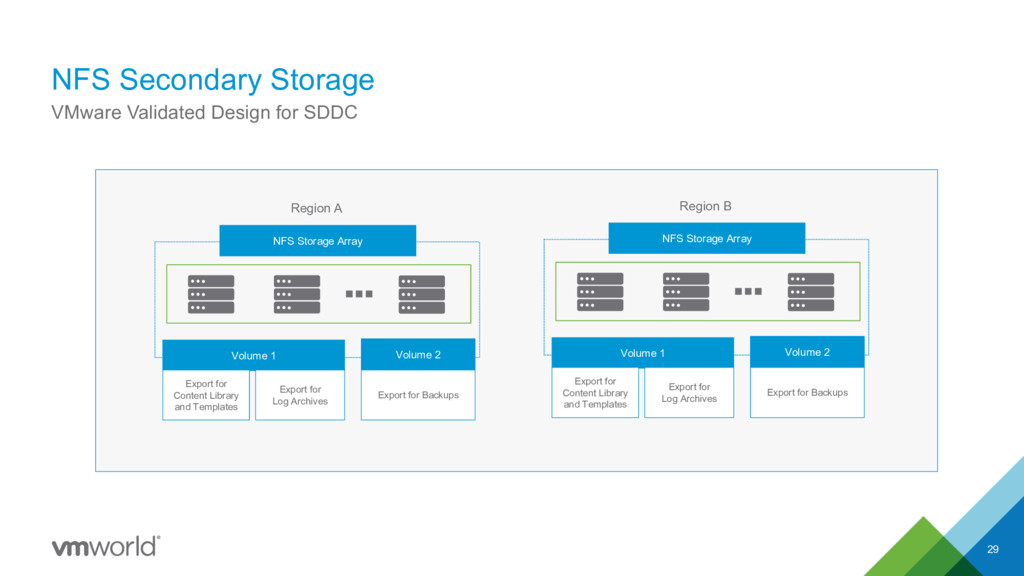
1 Volume 2 NFS Storage Array Region A Export for Backups Export for Content Library and Templates Export for Log Archives Volume 1 Volume 2 NFS Storage Array Region B Export for Backups Export for Content Library and Templates Export for Log Archives
time when creating signed certificates. See VMware Knowledge Base article 2146215. Certificate Mode § VMCA Hybrid Mode § All user-facing certificates are signed by a certificate authority (CA). § All virtual infrastructure management components use TLS/SSL certificates that are signed by the VMware Certificate Authority (VMCA). § Supports a Two-Layer CA environment. Certificate Replacement § If the CA-signed certificates expire after you deploy the SDDC, you must replace them individually on each affected component. § Provides guidance for replacing all CA-signed certificates that are expiring. * VMware Validated Design for SDDC
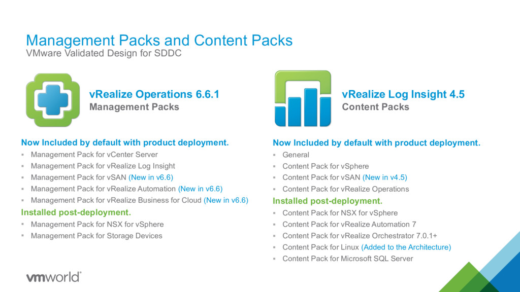
Now Included by default with product deployment. § Management Pack for vCenter Server § Management Pack for vRealize Log Insight § Management Pack for vSAN (New in v6.6) § Management Pack for vRealize Automation (New in v6.6) § Management Pack for vRealize Business for Cloud (New in v6.6) Installed post-deployment. § Management Pack for NSX for vSphere § Management Pack for Storage Devices Now Included by default with product deployment. § General § Content Pack for vSphere § Content Pack for vSAN (New in v4.5) § Content Pack for vRealize Operations Installed post-deployment. § Content Pack for NSX for vSphere § Content Pack for vRealize Automation 7 § Content Pack for vRealize Orchestrator 7.0.1+ § Content Pack for Linux (Added to the Architecture) § Content Pack for Microsoft SQL Server vRealize Operations 6.6.1 Management Packs vRealize Log Insight 4.5 Content Packs
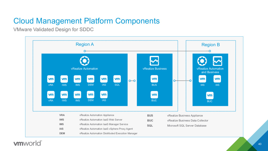
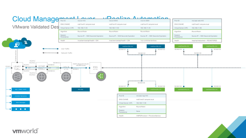
IWS IMS DEM IAS SQL vRA IWS IMS DEM IAS Region B IAS Cloud Management Platform Components 40 VMware Validated Design for SDDC BUS vRealize Business Appliance BUC vRealize Business Data Collector SQL Microsoft SQL Server Database VRA vRealize Automation Appliance IWS vRealize Automation IaaS Web Server IMS vRealize Automation IaaS Manager Service IAS vRealize Automation IaaS vSphere Proxy Agent DEM vRealize Automation Distributed Execution Manager BUC IAS vRealize Automation and Business
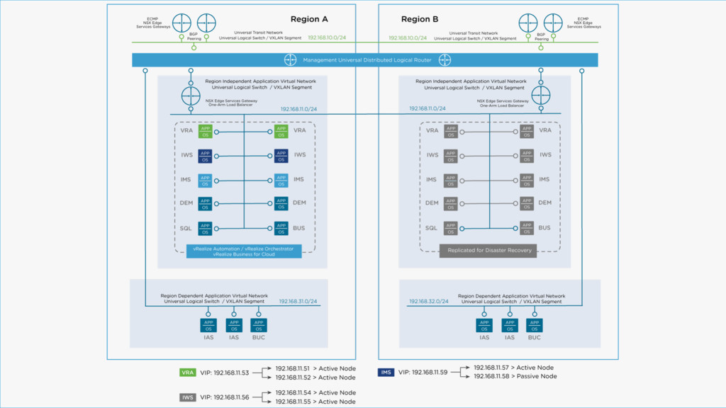
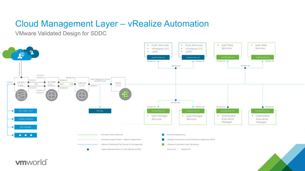
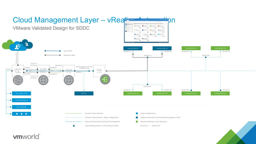
SDDC User Traffic Network Traffic Pool ID vra-iaas-mgr-443 DNS CNAME vra01ims01.rainpole.local Virtual Server (VIP) 192.168.11.59 Algorithm Round-Robin Session Persistence None Health /VMPSProvision = ProvisionService Pool ID vra-iaas-web-443 DNS CNAME vra01iws01.rainpole.local Virtual Server (VIP) 192.168.11.56 Algorithm Round-Robin Session Persistence Source IP – 1800 Seconds Expiration Health /wapi/api/status/web = REGISTERED Pool ID vra-svr-443 vra-svr-8443 vra-vro-8283 DNS CNAME vra01svr01.rainpole.local vra01svr01.rainpole.local vra01svr01.rainpole.local Virtual Server (VIP) 192.168.11.53 192.168.11.53 192.168.11.53 Algorithm Round-Robin Round-Robin Round-Robin Session Persistence Source IP – 1800 Seconds Expiration Source IP – 1800 Seconds Expiration Source IP – 1800 Seconds Expiration Health /vcac/services/api/health = 204 /vcac/services/api/health = 204 /vco-controlcenter/docs
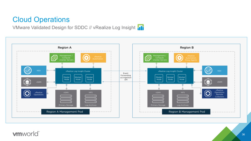
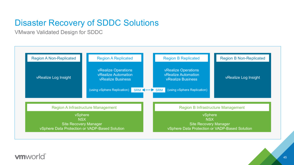
SDDC Region A Non-Replicated vRealize Log Insight Region A Infrastructure Management vSphere NSX Site Recovery Manager vSphere Data Protection or VADP-Based Solution Region A Replicated vRealize Operations vRealize Automation vRealize Business SRM (using vSphere Replication) Region B Infrastructure Management vSphere NSX Site Recovery Manager vSphere Data Protection or VADP-Based Solution Region B Non-Replicated vRealize Log Insight Region B Replicated vRealize Operations vRealize Automation vRealize Business SRM (using vSphere Replication)
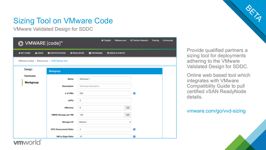
tool for deployments adhering to the VMware Validated Design for SDDC. Online web based tool which integrates with VMware Compatibility Guide to pull certified vSAN ReadyNode details. vmware.com/go/vvd-sizing VMware Validated Design for SDDC