Upgrade to Pro — share decks privately, control downloads, hide ads and more …

CNC

Sponsored · Your Podcast. Everywhere. Effortlessly. Share. Educate. Inspire. Entertain. You do you. We'll handle the rest.
Avatar for Ankit Jadon Ankit Jadon
May 15, 2021
260

 CNC

Avatar for Ankit Jadon

Ankit Jadon

May 15, 2021
Tweet

Transcript

  1. What is a CNC Machine? CNC : Computerised Numerical Control

    (Computer + Numerical Control) • Numerical control is a programmable automation in which process is controlled by Numbers, Letters, and symbols. • CNC Machining is a process used in the manufacturing sector that involves the use of computers to control machine tools like lathes, mills and grinders. 1
  2. Why is CNC Machining necessary? • To manufacture complex curved

    geometries in 2D or 3D was extremely expensive by mechanical means (which usually would require complex jigs to control the cutter motions) • Machining components with high Repeatability and Precision • Unmanned machining operations • To improve production planning and to increase productivity • To survive in global market CNC machines are must to achieve close tolerances. 2
  3. • However, since the groove in the ball screw is

    helical, its steel balls roll along the helical groove, and, then, they may go out of the ball nut unless they are arrested at a certain spot. • It consists of a screw spindle, a nut, balls and integrated ball return mechanism a shown in Figure . • The flanged nut is attached to the moving part of CNC machine tool. As the screw rotates, the nut translates the moving part along the guide ways. Ball screw / ball bearing screw / recirculating ballscrew Mechanism Ballscrew configuration 3
  4. • Thus, it is necessary to change their path after

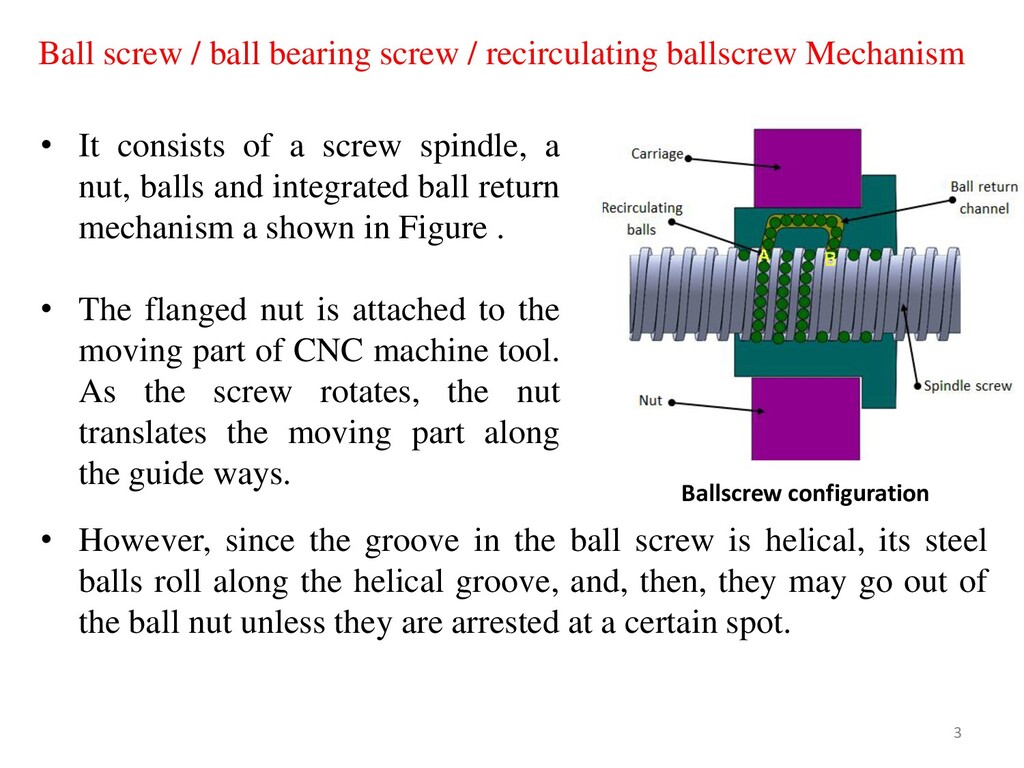
    they have reached a certain spot by guiding them, one after another, back to their “starting point” (formation of a recirculation path). The recirculation parts play that role. • When the screw shaft is rotating, as shown in Figure, a steel ball at point (A) travels 3 turns of screw groove, rolling along the grooves of the screw shaft and the ball nut, and eventually reaches point (B). • Then, the ball is forced to change its pathway at the tip of the tube, passing back through the tube, until it finally returns to point (A). • Whenever the nut strokes on the screw shaft, the balls repeat the same recirculation inside the return tube. 4
  5. • When debris or foreign matter enter the inside of

    the nut, it could affect smoothness in operation or cause premature wearing, either of which could adversely affect the ball screw's functions. • To prevent such things from occurring, seals are provided to keep contaminants out. There are various types of seals viz. plastic seal or brush type of seal used in ball-screw drives. 5
  6. Characteristics of ball screws • High mechanical efficiency In ball

    screws, about 90% or more of the force used to rotate the screw shaft can be converted to the force to move the ball nut. Since friction loss is extremely low, the amount of force used to rotate the screw shaft is as low as one third of that needed for the acme thread lead screw. • Low in wear Because of rolling contact, wear is less than that of sliding contact. Thus, the accuracy is high. Ball screws move smoothly enough under very slow speed. They run smoothly even under a load. 6
  7. Thread forms (a) Gothic arc (b) Circular arc • Thread

    Form The thread form used in these screws can either be gothic arc type (fig.a) or circular arc type (fig.b). The friction in this kind of arrangement is of rolling type. This reduces its wear as comparison with conventional sliding friction screws drives. Recirculating ball screws are of two types. In one arrangement the balls are returned using an external tube. In the other arrangement the balls are returned to the start of the thread in the nut through a channel inside the nut. 7
  8. • Preloading In order to obtain bidirectional motion of the

    carriage without any positional error, the backlash between the nut and screw should be minimum. Zero backlash can be obtained by fitting two nuts with preloading (tension or compression) or by applying a load which exceeds the maximum operating load. Figure shows double nut preloading system. A shim plate (spacer) is inserted between two nuts for preloading. Preload is to create elastic deformations (deflections) in steel balls and ball grooves in the nut and the screw shaft in advance by providing an axial load. Double nut preloading system 8
  9. As a result the balls in one of the nuts

    contact the one side of the thread and balls in the other nut contact the opposite side. Effects of preload • Zero backlash: It eliminates axial play between a screw shaft and a ball nut. • It minimizes elastic deformation caused by external force, thus the rigidity enhances. • In case mounting errors, misalignment between the screw shaft and the nut may occur this further generates distortion forces. • This could lead to the problems such as, Shortened service life Adverse effect on smooth operation Reduced positioning accuracy Generation of noise or vibration Breakage of screw shaft 9
  10. Advantages of ball screws • Highly efficient and reliable. •

    Less starting torque. • Lower co efficient of friction compared to sliding type screws and run at cooler temperatures • Power transmission efficiency is very high and is of the order of 95 %. • Could be easily preloaded to eliminate backlash. • The friction force is virtually independent of the travel velocity and the friction at rest is very small; consequently, the stick-slip phenomenon is practically absent, ensuring uniformity of motion. • Has longer thread life hence need to be replaced less frequently. • Ball screws are well -suited to high through output, high speed applications or those with continuous or long cycle times. • Smooth movement over full range of travel. 10
  11. Disadvantages of ball screws • Tend to vibrate. • Require

    periodic overhauling to maintain their efficiency. • Inclusion of dirt or foreign particles reduces the life of the screws. • Not as stiff as other power screws, thus deflection and critical speed can cause difficulties. • They are not self-locking screws hence cannot be used in holding devices such as vices. • Require high levels of lubrication. 11
  12. Applications of ball screws • Ball screws are employed in

    cutting machines, such as machining center and NC lathe where accurate positioning of the table is desired • Used in the equipment's such as lithographic equipment or inspection apparatus where precise positioning is vital • High precision ball screws are used in steppers for semiconductor manufacturing industries for precision assembly of micro parts. • Used in robotics application where precision positioning is needed. • Used in medical examination equipment's since they are highly accurate and provide smooth motion. 12
  13. DIFFERENCES BETWEEN CNC MACHINES TOOLS AND CONVENTIONAL MACHINE TOOLS 

    Constructional details: • Basically conventional machine have 2 axes, known as X & Y axis. • There is also a Z axis long which only the bed moves vertically. • The spindle along with the tool does not move as it is fixed with the machine body . But in case of CNC machine, there are minimum 3 axes with Spindle moving parallel to Z axis. 13
  14. The structure of the CNC machine is therefore designed to

    cope with the torsional forces and heavy duty cutting imposed on these machines. • CNC machines have more rigid construction when compared to the conventional machine. • The slide ways, guide and spindles of the CNC machine all look over proportioned when compared to the conventional machine. 14
  15.  Recirculating ball lead screws and anti friction slide ways

    • The slide ways on a conventional machine operate under the conditions of sliding friction. • The lead screws are usually of the Acme thread form, which are inefficient due to the high frictional resistance between the flanks of the screw and the nut. There is also backlash, because of the clearance between the screw and the nut. CONVENTIONAL 15
  16. • Rolling friction can be used instead of sliding friction,

    where re-circulating roller bearings are positioned under the slide ways. • A recirculating ball lead screw, where both the lead screw and the nut have a precision ground radiused shaped thread. The space or track between the lead screw and nut is filled with an endless stream or ball bearings. The advantages are longer life, less frictional resistance, lower torque required, more precise positioning of slides, where backlash is almost completely eliminated. CNC 16
  17.  Use of Stepping Motors in Slide Movement The slides

    and spindle of the CNC machine are driven by stepper motors. STEPPER MOTOR – A digital signal is sent from the controller to the motor in the form of pulses, which will cause the motor to rotate through a specified angle, which causes the slide to move by the required distance. 17
  18. Example: If five digital pulses are sent to the stepper

    motor then it will rotate by five steps, which is converted to linear movement by the lead screw. The speed by which the pulses are sent to the stepper motor will determine the velocity of the slide movement. As the distance moved by the slide and the feed can be accurately controlled by the CNC control system, there is no need for positional or velocity feedback 18
  19. MAJOR COMPONENTS RELATED TO CNC MACHINE TOOLS Any CNC machine

    tool essentially consists of the following parts: Part program: • A series of coded instructions required to produce a part. • Controls the movement of the machine tool and on/off control of auxiliary functions such as spindle rotation and coolant. • The coded instructions are composed of letters, numbers and symbols. 19
  20. Program input device • The program input device is the

    means for part program to be entered into the CNC control. • Three commonly used program input devices are punch tape reader, magnetic tape reader, and computer via RS-232-C communication. 20
  21. Machine Control Unit The machine control unit (MCU) is the

    heart of a CNC system. It is used to perform the following functions: • To read the coded instructions. • To decode the coded instructions. • To implement interpolations (linear, circular, and helical) to generate axis motion commands. • To feed the axis motion commands to the amplifier circuits for driving the axis mechanisms. • To receive the feedback signals of position and speed for each drive axis. • To implement auxiliary control functions such as coolant or spindle on/off and tool change. 21
  22. Machine Tool • CNC controls are used to control various

    types of machine tools. • Regardless of which type of machine tool is controlled, it always has a slide table and a spindle to control position and speed. • The machine table is controlled in the X and Y axes, while the spindle runs along the Z axis. 22
  23. Feed Back System • The feedback system is also referred

    to as the measuring system. • It uses position and speed transducers to continuously monitor the position at which the cutting tool is located at any particular instant. • The MCU uses the difference between reference signals and feedback signals to generate the control signals for correcting position and speed errors. 23
  24. Drive System • Drives are used to provide controlled motion

    to CNC elements • A drive system consists of amplifier circuits, drive motors, and ball lead-screws. • The MCU feeds the control signals (position and speed) of each axis to the amplifier circuits. • The control signals are augmented to actuate drive motors which in turn rotate the ball lead-screws to position the machine table. 24
  25. • In machine tools, power is generally required for driving

    the main spindle, saddles and carriages and to some auxiliary units. • The motors used for CNC system are of two kinds  Electrical - AC , DC or Stepper motors  Fluid - Hydraulic or Pneumatic • In CNC, usually stepper and servo electrical drives are used • They exhibit favourable torque-speed characteristics and are relatively inexpensive.  POWER DRIVES 25
  26.  STEPPER MOTOR A stepper motor is a pulse-driven motor

    that changes the angular position of the rotor in steps. Due to this nature of a stepper motor, it is widely used in low cost, open loop position control systems. Types of stepper motors: o Permanent Magnet Employ permanent magnet Low speed, relatively high torque o Variable Reluctance Does not have permanent magnet Low torque 26
  27. • Rotor is a permanent magnet. • PM motor rotor

    has no teeth and is designed to be magnetized at a right angle to its axis. Permanent magnet stepper Permanent magnet (PM) stepper motor • These are low cost motors with typical step angle ranging between 7.5⁰ to 15⁰ • Figure shows a simple, 90⁰ PM motor with four phases (A-D). • Applying current to each phase in sequence will cause the rotor to rotate by adjusting to the changing magnetic fields. • Although it operates at fairly low speed, the PM motor has a relatively high torque characteristic. 27
  28. • It attracts the metal rotor. When the windings are

    energized in a reoccurring sequence of 2, 3, 1, and so on, the motor will rotate in a 30⁰ step angle. • In the non-energized condition, there is no magnetic flux in the air gap, as the stator is an electromagnet and the rotor is a piece of soft iron; hence, there is no detent torque. Fig. Variable reluctance stepper motor Variable Reluctance Motor • The cylindrical rotor is made of soft steel and has four poles • It has four rotor teeth, 90⁰ apart and six stator poles, 60⁰ apart. • Electromagnetic field is produced by activating the stator coils in sequence. 28
  29. Hybrid stepper motor • Hybrid stepping motors combine a permanent

    magnet and a rotor with metal teeth to provide features of the variable reluctance and permanent magnet motors together. • The number of rotor pole pairs is equal to the number of teeth on one of the rotor's parts. The hybrid motor stator has teeth creating more poles than the main poles windings Hybrid stepper 29
  30. • Rotation of a hybrid stepping motor is produced in

    the similar fashion as a permanent magnet stepping motor, by energizing individual windings in a positive or negative direction. • When a winding is energized, north and south poles are created, depending on the polarity of the current flowing. • These generated poles attract the permanent poles of the rotor and also the finer metal teeth present on rotor. 30
  31. • The rotor moves one step to align the offset

    magnetized rotor teeth to the corresponding energized windings. • Hybrid motors are more expensive than motors with permanent magnets, but they use smaller steps, have greater torque and maximum speed. • Step angle of a stepper motor is given by, 31
  32. Advantages of stepper motors • Low cost • Ruggedness •

    Simplicity of construction • Low maintenance • Less likely to stall or slip • Will work in any environment • Excellent start-stop and reversing responses Disadvantages of stepper motors • Low torque capacity compared to DC motors • Limited speed • During overloading, the synchronization will be broken. Vibration and noise occur when running at high speed. 32
  33. • Servomotors are special electromechanical devices that produce precise degrees

    of rotation. • A servo motor is a DC or AC or brushless DC motor combined with a position sensing device. • Servomotors are also called control motors as they are involved in controlling a mechanical system. • The servomotors are used in a closed-loop servo system as shown in Figure A reference input is sent to the servo amplifier, which controls the speed of the servomotor. Servo system block diagram  SERVO MOTORS 33
  34. • A feedback device is mounted on the machine, which

    is either an encoder or resolver. • This device changes mechanical motion into electrical signals and is used as a feedback. • This feedback is sent to the error detector , which compares the actual operation with that of the reference input. • If there is an error, that error is fed directly to the amplifier, which will be used to make necessary corrections in control action. 34
  35. • In many servo systems, both velocity and position are

    monitored. • Servomotors provide accurate speed, torque, and have ability of direction control. DC servomotors DC operated servomotors are usually respond to error signal abruptly and accelerate the load quickly. A DC servo motor is actually an assembly of four separate components, namely: o DC motor o gear assembly o position-sensing device o control circuit 35
  36. AC servo motor • Magnetic force is generated by a

    permanent magnet and current which further produce the torque. • It has no brushes so there is little noise/vibration. This motor provides high precision control with the help of high resolution encoder. • The stator is composed of a core and a winding. The rotor part comprises of shaft, rotor core and a permanent magnet. • Digital encoder can be of optical or magnetic type. It gives digital signals, which are in proportion of rotation of the shaft. 36
  37. Advantages of servo motors • Provides high intermittent torque, high

    torque to inertia ratio, and high speeds • Work well for velocity control • Available in all sizes • Quiet in operation • Smoother rotation at lower speeds Disadvantages of servo motors • More expensive than stepper motors • Require tuning of control loop parameters • Not suitable for hazardous environments or in vacuum • Excessive current can result in partial demagnetization of DC type servo motor 37
  38.  LINEAR MOTION DRIVES • Linear motion drives are mechanical

    transmission systems which are used to convert rotary motion into linear motion. • The conventional thread forms like vee or square are not suitable in CNC because of their high wear and less efficiency. • Therefore CNC machines generally employ ball screw for driving their workpiece carriages. • These drives provide backlash free operation with low friction- wear characteristics. • These are efficient and accurate in comparison with that of nut- and-screw drives. Most widely used linear motion drives are ball screws. 38
  39. INTRODUCTION A group of commands given to the CNC for

    operating the machine is called the program. It consists of: • Information about part geometry • Motion statements to move the cutting tool • Cutting speed • Feed • Auxiliary functions such as coolant on and off, spindle direction 40
  40. There are four basic terms used in CNC programming Character

    -> Word -> Block -> Program  CNC program structure • Character is the smallest unit of CNC program. It can have Digit / Letter / Symbol. • Word is a combination of alpha-numerical characters. This creates a single instruction to the CNC machine. Each word begins with a capital letter, followed by a numeral. These are used to represent axes positions, federate, speed, preparatory commands, and miscellaneous functions. • A program block may contain multiple words, sequenced in a logical order of processing. • The program comprises of multiple lines of instructions, „blocks‟ which will be executed by the machine control unit (MCU). 41
  41. Fixed zero: • Origin is always located at some position

    on M/C table (usually at south west corner/Lower left-hand) of the tables & all tool location are defined W.R.T. this zero Floating Zero: • Very common with CNC M/C used now a days. • Operator sets zero point at any convenient position on M/C table. • The Coordinate system is knows as work coordinate system (WCS) FIXED ZERO v/s FLOATING ZERO 42
  42. Modal and Non modal commands • Commands issued in the

    NC program may stay in effect indefinitely (until they explicitly cancelled or changed by some other command), or they may be effective for only the one time that they are issued. • The former are referred as Modal commands. Examples include feed rate selection and coolant selection. • Commands that are effective only when issued and whose effects are lost for subsequent commands are referred to as non-modal commands. • A dwell command, which instructs the tool to remain in a given configuration for a given amount of time, is an example of a non-modal command. 43
  43. • An NC part program is made up of a

    series of commands that are input into the MCU in a serial manner. • The MCU interprets these commands and generates the necessary signals to each of the drive units of the machine to accomplish the required action. • The NC program is required to have a particular structure that the controller can understand and it must follow a specific syntax. • Commands are inputs into the controller in units called blocks or statements. • Each block is made up of one or more machine commands. Structure of an NC part program 44
  44. • In general, several commands are grouped together to accomplish

    a specific machining operation, hence the use of a block of information for each operation. • Each command gives a specific element of control data, such as dimension or a feed rate. Each command within a block is also called a word. • The way in which words are arranged within the block is called block format. • Three different block formats are commonly used, (Fixed sequential format, Tab sequential format and Word address format) 45
  45. • With this type of format, each type of word

    is assigned as address that is identified by a letter code within the part program. • Thus the letter code specifies the type of word that follows and then its associated numeric data is given. • For example, the code T represents a tool number. Thus a word of the form T01 would represent tool number 1. • Theoretically, with this approach, the words in a given block can be entered in any sequence and the controller should be able to interpret them correctly. Word Sequential Format : Used on virtually all modern controllers. N50 G00 X50 Y25 Z0 F0 N60 G01 Z-1 F50 M08 N70 Z0 M09 46
  46. • With the word address format only the needed words

    for a given operation have to be included within the block. • The command to which the particular numeric data applies is identified by the preceding address code. • Word format has the advantage of having more than one particular command in one block something that would be impossible in the other two formats. 47
  47. • N-CODE: Sequence number, used to identify each block with

    in an NC program and provides a means by which NC commands may be rapidly located. It is program line number. It is a good practice to increment each block number by 5 to 10 to allow additional blocks to be inserted if future changes are required. • G-CODE: Preparatory Word, used as a communication device to prepare the MCU. The G-code indicates that a given control function such as G01, linear interpolation, is to be requested. • X, Y & Z-CODES: Coordinates. These give the coordinate positions of the tool. COMMONLY USED WORD ADDRESSES 48
  48. • F-CODE: Feed rate. The F code specifies the feed

    in the machining operation. • S-CODE: Spindle speed. The S code specifies the cutting speed of the machining process. • T-CODE: Tool selection. The T code specifies which tool is to be used in a specific operation. • M-CODE: Miscellaneous function. The M code is used to designate a particular mode of operation for an NC machine tool. • I, J & K-CODES: They specify the centre of arc coordinates from starting. 49
  49. Sequence and format of words: N3 G2 X+1.4 Y+1.4 Z+1.4

    I2.0 J2.0 K2.0 F5 S4 T4 M2 sequence no preparatory function destination coordinates dist to center of circle feed rate spindle speed tool Other function
  50. 51

  51. List of M codes M codes vary from machine to

    machine depending on the functions available on it. They are decided by the manufacturer of the machine. The M codes listed below are the common ones. 52
  52. G00 Rapid traverse When the tool being positioned at a

    point preparatory to a cutting motion, to save time it is moved along a straight line at Rapid traverse, at a fixed traverse rate which is pre-programmed into the machine's control system. Typical rapid traverse rates are 10 to 25 m /min., but can be as high as 80 m/min. Syntax: N010 [G90/G91] G00 X10 Y10 Z5
  53. G01 Linear interpolation (feed traverse) The tool moves along a

    straight line in one or two axis simultaneously at a programmed linear speed, the feed rate. Syntax: N010[G90/G91] G01 X10 Y10 Z5 F25
  54. G02/G03 Circular interpolation Format N__ G02/03 X__ Y__Z__ I__ J__K__

    F__ using the arc center or N__ G02/03 X__ Y__Z__ R__ F__ using the arc radius Arc center The arc center is specified by addresses I, J and K. I, J and K are the X, Y and Z co-ordinates of the arc center with reference to the arc start point. G02 moves along a CW arc G03 moves along a CCW arc
  55. G90 ABSOLUTE POSITION COMMAND • When using a G90 absolute

    position command, each dimension or move is referenced from a fixed point, known as ABSOLUTE ZERO (part zero). • Absolute zero is usually set at the corner edge of a part, or at the center of a square or round part, or an existing bore. ABSOLUTE ZERO is where the dimensions of a part program are defined from. • Absolute dimensions are referenced from a known point on the part, and can be any point the operator chooses, such as the upper-left corner, center of a round part, or an existing bore. Syntax: N.. G90 X.. Y.. Z.. A.. B.. C..
  56. G91 INCREMENTAL POSITION COMMAND • This code is modal and

    changes the way axis motion commands are interpreted. G91 makes all subsequent commands incremental. Zero point shifts with the new position. Syntax: N.. G91 X.. Y.. Z.. A.. B.. C..
  57. G 17 : XY plane selection Syntax: N.. G17 G

    17 G18 G19 : PLANE SELECTION G 19 : ZY plane selection Syntax: N.. G19 G 18 : ZX plane selection Syntax: N.. G18 Syntax: N020 G17 G75 F6.0 S300 T1001 M08
  58. G 70 Inch data input G 71 Metric data input

    Syntax : N010 G70 G90 G94 G97 M04
  59. Manual Part Programming Example Tool size = 0.25 inch, Feed

    rate = 6 inch per minute, Cutting speed = 300 rpm, Tool start position: 2.0, 2.0 Programming in inches (4, 4) (2, 2) 5” p0 p1 p2 5” 2.5” 1” 45° p3 p4 p5 Motion of tool: p0  p1  p2  p3  p4  p5  p1  p0
  60. Spindle CCW (4, 4) (2, 2) 5” p0 p1 p2

    5” 2.5” 1” 45° p3 p4 p5 1. Set up the programming parameters N010 G70 G90 G94 G97 M04 Programming in inches Use absolute coordinates Spindle speed in rpm Feed in ipm
  61. Flood coolant ON (4, 4) (2, 2) 5” p0 p1

    p2 5” 2.5” 1” 45° p3 p4 p5 2. Set up the machining conditions N020 G17 G75 F6.0 S300 T1001 M08 Machine moves in XY-plane Feed rate Tool no. Spindle speed Use full-circle interpolation
  62. (4, 4) (2, 2) 5” p0 p1 p2 5” 2.5”

    1” 45° p3 p4 p5 3. Move tool from p0 to p1 in straight line N030 G01 X3.875 Y3.698 Linear interpolation target coordinates
  63. (4, 4) (2, 2) 5” p0 p1 p2 5” 2.5”

    1” 45° p3 p4 p5 4. Cut profile from p1 to p2 N040 G01 X3.875 Y9.125 Linear interpolation target coordinates N040 G01 Y9.125 X-coordinate does not change  no need to program it or
  64. (4, 4) (2, 2) 5” p0 p1 p2 5” 2.5”

    1” 45° p3 p4 p5 5. Cut profile from p2 to p3 N050 G01 X5.634 Y9.125 Linear interpolation target coordinates 1” p3 .125 (x, y) (6.5, 9) y = 9 + 0.125 = 9.125 (6.5 - x)2 + 0.1252 = (1 - 0.125)2 x = 5.634
  65. coordinates of center of circle (4, 4) (2, 2) 5”

    p0 p1 p2 5” 2.5” 1” 45° p3 p4 p5 6. Cut along circle from p3 to p4 N060 G03 X7.366 Y9.125 I6.5 J9.0 circular interpolation, CCW motion target coordinates N060 G03 X7.366 Y9.125 I0.866 J-0.125
  66. (4, 4) (2, 2) 5” p0 p1 p2 5” 2.5”

    1” 45° p3 p4 p5 7. Cut from p4 to p5 N070 G01 X9.302 target coordinates (Y is unchanged) Linear interpolation
  67. (4, 4) (2, 2) 5” p0 p1 p2 5” 2.5”

    1” 45° p3 p4 p5 8. Cut from p5 to p1 N080 G01 X3.875 Y3.698 target coordinates (see step 3) Linear interpolation
  68. (4, 4) (2, 2) 5” p0 p1 p2 5” 2.5”

    1” 45° p3 p4 p5 9. Return to home position, stop program N090 G01 X2.0 Y2.0 M30 end of data target coordinates (see step 3) Linear interpolation N100 M00 program stop
  69. 10. Complete RS-274 program N010 G70 G90 G94 G97 M04

    N020 G17 G75 F6.0 S300 T1001 M08 N030 G01 X3.875 Y3.698 N040 G01 X3.875 Y9.125 N050 G01 X5.634 Y9.125 N060 G03 X7.366 Y9.125 I0.866 J-0.125 N070 G01 X9.302 N080 G01 X3.875 Y3.698 N090 G01 X2.0 Y2.0 M30
  70. PART PROGRAM N5 M12 N10 T0101 N15 G0 X100 Z50

    N20 M3 S600 N25 M8 N30 G1 X50 Z0 F600 N40 Y-30 F200 N50 X80 Y-20 F150 N60 G0 X100 Z50 N70 T0100 N80 M5 N90 M9 N100 M13 N110 M30
  71. Code Explanation N5 Clamping workpiece N10 Changing No.1 tool and

    executing its offset N15 Rapidly positioning to A point N20 Starting the spindle with 600 r/min N25 Cooling ON N30 Approaching B point with 600mm/min N40 Cutting from B point to C point N50 Cutting from C point to D point N60 Rapidly retracting to A point N70 Cancelling the tool offset N80 Stopping the spindle N90 Cooling OFF N100 Releasing workpiece N110 End of program, spindle stopping and Cooling OFF
  72. N5 G90 G71 N10 T1 M6 N15 G92 X-100 Y86

    Z95 N20 G0 X0 Y0 S2500 M3 N25 Z12.5 N30 G1 Z-12.5 F150 N35 X-20 Y30 N40 G2 X10 Y100 R80 N45 G1 X140 Y60 N50 G2 X150 Y0 R50 N55 G1 X0 Y0 N60 G0 Z12.5 N65 G91 G28 Z0 M5 N70 G91 G28 X0 Y0 N75 M30
  73. CODE EXPLANATION N5 absolute positioning, metric unit N10 tool change

    to T1 N15 define work zero point at A N20 rapid traverse to A, spindle on (2500 RPM, CW) N25 rapid plunge to 12.5 mm above Z0 N30 feed to Z-12.5, feed rate 150 MMPM N35 cut line AB to B N40 cut arc BC to C N45 cut line CD to D N50 cut arc DE to E N55 cut line EA to A N60 rapid retract to Z12.5 N65 reference point return in Z direction, spindle off N70 reference point return in X and Y directions N75 end of program
  74. N1 T16 M06 N2 G90 G54 G00 X0.5 Y-0.5 N3

    S1450 M03 N4 G43 H16 Z1. M08 N5 G81 G99 Z-0.375 R0.1 F9. N6 X1.5 N7 Y-1.5 N8 X0.5 N9 G80 G00 Z1. M09 N10 G53 G49 Z0. M05 N11 M30
  75. CODE EXPLANATION N1- Tool change (M06) to tool no.16 N2-

    Tool rapidly moves (G00) to first drilling position X0.5 Y-0.5 while taking into account Zero-offset-no. 1 (G54) N3- Drill starts rotating clockwise (M03) with 1450 rpm (S1450). N4- Drill takes depth Z1. taking into account tool length compensation (G43 H16), coolant is turned on (M08). N5- Drilling cycle (G81) parameters, drill depth (Z) and cutting feed (F) are given, with this command first drill is made at current position (X0.5 Y-0.5). N6- As drilling cycle continues it’s work with every axis movement so next drill is done at X1.5 N7- Third drilling hole at Y-1.5
  76. N8- Fourth drill at X0.5 N9- Drilling cycle is cancelled

    (G80), Coolant is turned off (M09). N10- Taking Machine-coordinate-system (G53) into account the drill is taken to Z0 position. Tool length compensation is cancelled (G49), cutter rotation is stopped (M05). N11- CNC part-program is ended.
  77. Write a part program for turning operations being carried out

    on a CNC turning center. Let us take an exercise: Figure shows the final profile to be generated on a bar stock by using a CNC turning center. After studying the required part geometry and features, the main program can be written as follows. Typical PROGRAMMING - TURNING OPERATIONS Figure A component to be turned. 81
  78. 82