Upgrade to Pro — share decks privately, control downloads, hide ads and more …

Complete Formal Hardware Verification of Interfaces for a FlexRay-like Bus

Complete Formal Hardware Verification of Interfaces for a FlexRay-like Bus

Christian Müller

July 17, 2011
Tweet

More Decks by Christian Müller

Other Decks in Science

Transcript

  1. The Problem Computational Model Proof Sketch Summary Complete Formal Hardware

    Verification of Interfaces for a FlexRay-like Bus CAV 2011 Christian M¨ uller and Wolfgang Paul Saarland University, Germany 17/07/2011 U N IV E R SIT A S S A R A V I E N S I S
  2. The Problem Computational Model Proof Sketch Summary The (easy) Problem

    CPU0 ECU0 RBi SBi RB¬i SB¬i . . . ECUsend(s) CPUsend(s) RBi SBi RB¬i SB¬i . . . ECUp−1 CPUp−1 RBi SBi RB¬i SB¬i Bus TDMA communication: rounds r, slots s ∈ [0 : ns − 1] buffer index i = s mod 2 (⇒ ns has to be even) sender schedule send : [0 : ns − 1] → [0 : p − 1] one slot lasts T cycles slot start: α(r, s) = (ns · r + s) · T
  3. The Problem Computational Model Proof Sketch Summary The (easy) Problem

    CPU0 ECU0 RBi SBi RB¬i SB¬i . . . ECUsend(s) CPUsend(s) RBi SBi RB¬i SB¬i . . . ECUp−1 CPUp−1 RBi SBi RB¬i SB¬i Bus TDMA communication: rounds r, slots s ∈ [0 : ns − 1] buffer index i = s mod 2 (⇒ ns has to be even) sender schedule send : [0 : ns − 1] → [0 : p − 1] one slot lasts T cycles slot start: α(r, s) = (ns · r + s) · T Theorem ∀u : ECUsend(s).SBαsend(s) (r,s) s mod 2 = ECUu.RBαu(r,s+1) (s+1) mod 2
  4. The Problem Computational Model Proof Sketch Summary The (hard) Problem

    The same theorem but for asynchronous system? one ECU ≡ one clock domain clock period τu of ECUu bounded clock drift: ∀u, v : τv · (1 − ∆) ≤ τu ≤ τv · (1 + ∆) clock synchronization inevitable αu (r, s) = αu (r, 0) + s · T · τu αu (r, 0) depends on a synchronization in round r Theorem ∀u : ECUsend(s).SBαsend(s) (r,s) s mod 2 = ECUu.RBαu(r,s+1) (s+1) mod 2
  5. The Problem Computational Model Proof Sketch Summary Problems To Solve

    The Problem Register Models cture 0. Computational model for asynchronous hardware 1. Correctness of Serial Interfaces: (a) Signal Transfer across Clock Domains; (b) Low-level Clock Synchronization. 2. Clock (Timer) Synchronization. 3. Bus Contention Control. 4. Sync Message Transfer Over the Bus 5. Payload Message Transfer Background The Problem Proof Structure Unavoidable cyclic argument: - timers roughly synchronized - enough to control bus for sync message - send sync message across domains resyn- chronize
  6. The Problem Computational Model Proof Sketch Summary Problems To Solve

    The Problem Register Models cture 0. Computational model for asynchronous hardware 1. Correctness of Serial Interfaces: (a) Signal Transfer across Clock Domains; (b) Low-level Clock Synchronization. 2. Clock (Timer) Synchronization. 3. Bus Contention Control. 4. Sync Message Transfer Over the Bus 5. Payload Message Transfer Background The Problem Proof Structure Unavoidable cyclic argument: - timers roughly synchronized - enough to control bus for sync message - send sync message across domains resyn- chronize The proof of isolated problems must break the cycle!
  7. The Problem Computational Model Proof Sketch Summary Previous Results CDC

    message transmission (Problems 1, 5) by Schmaltz (abstracting 2, 3, 4) S R clks clkr
  8. The Problem Computational Model Proof Sketch Summary Previous Results CDC

    message transmission (Problems 1, 5) by Schmaltz (abstracting 2, 3, 4) S R clks clkr scheduler correctness & synchronization (Problems 2, 4) by B¨ ohm (assuming 3) ECUm ECU0 ... ECUp−1
  9. The Problem Computational Model Proof Sketch Summary Previous Results CDC

    message transmission (Problems 1, 5) by Schmaltz (abstracting 2, 3, 4) S R clks clkr scheduler correctness & synchronization (Problems 2, 4) by B¨ ohm (assuming 3) ECUm ECU0 ... ECUp−1 similar situation in related work
  10. The Problem Computational Model Proof Sketch Summary Digital Register Model

    out ce in clk R (a) Register clk in x ce 1 out y x c c + 1 (b) An Update in the Digital Register Model
  11. The Problem Computational Model Proof Sketch Summary Detailed Register Model

    clk in x ce 0 1 0 out y Ω x eu (c) eu (c ) th ts tpmin tpmax ... in ce 0 1 0 x Ω x clock edge: eu (c) = c · τu + γu setup & hold times: ts, th min & max propagation delays: tpmin , tpmax undefined value Ω (glitch) out : R → {0, 1, Ω}
  12. The Problem Computational Model Proof Sketch Summary Bus Model out1

    out2 outn bus bus(t) = out1(t) ∧ out2(t) ∧ · · · ∧ outn (t) bus : R → {0, 1, Ω} Ω ∧ x = x ∧ Ω = Ω
  13. The Problem Computational Model Proof Sketch Summary Bus Model out1

    out2 outn bus bus(t) = out1(t) ∧ out2(t) ∧ · · · ∧ outn (t) bus : R → {0, 1, Ω} Ω ∧ x = x ∧ Ω = Ω out1 out2 out3 bus Ω Ω Ω Ω
  14. The Problem Computational Model Proof Sketch Summary Low-level Bit Transmission

    Theorem (CDC Signal Transmission by Schmaltz) If the sender puts a bit b into its send register and keeps it constant for 8 cycles (FlexRay), then the receiver will sample the bit b during 7 + x cycles, with x ∈ {0, 1}. x depends on coupling of hardware cycles timing violated ⇒ x = 0 possible extended to multiple bits (bit-alignment!) direct connection assumed!
  15. The Problem Computational Model Proof Sketch Summary Clock Synchronization &

    Scheduler Simple Clock Synchronization: one master + many slaves Theorem (Synchronization Correctness by B¨ ohm) If all slaves are connected to the master directly, they will recognize the synchronization message and adjust their timers. Theorem (Transmission Window by B¨ ohm) If ECUs are synchronized, then their slots overlap enough to transmit a message. synchronization message transmission: by applying the Theorem of Schmaltz still direct connection assumed!
  16. The Problem Computational Model Proof Sketch Summary Proof Sketch The

    only assumptions: bounded clock drift meaningful configuration Theorem (*) The analog output of an non-sending ECUu is idle and spike-free. interplay of scheduler & serial sending interface propagating of digital properties down to the analog outputs
  17. The Problem Computational Model Proof Sketch Summary Overall Proof Theorem

    (Bus Control) The synchronization happens at the beginning of every round r and the bus is collision-free during every slot. The proof sketch (induction on round r): Base case (r = 0): after start, all ECUs are waiting for the 1st synchronization by Theorem (*) & bus model abstract the bus apply Synchronization Correctness of B¨ ohm by Scheduler Correctness of B¨ ohm show that slots overlap by Theorem (*) and send function abstract the bus to a direct connection during every slot Induction step (r → r + 1): Synchronization for round r is given by IH after round schedule all ECUs are idle, then apply Theorem (*) proceed as in Base case of the proof
  18. The Problem Computational Model Proof Sketch Summary Problems Discovered setup/hold

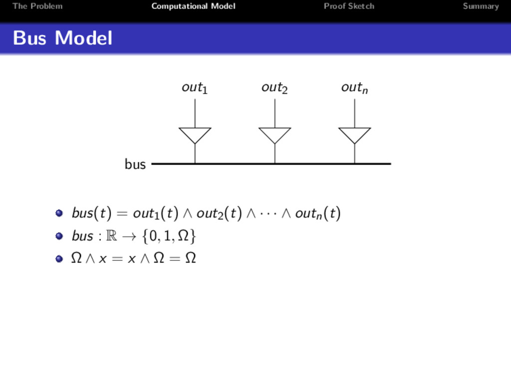
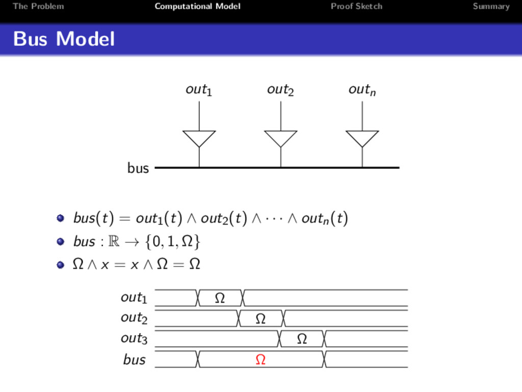
    time violation at synchronization: Case 1: incorrectly sampled ⇒ 1 cycle delay Case 2: correctly sampled ⇒ no delay (was missing) not discovered because only 1 round treated αu (r, s) defined by the automata state was verified: eu (αu (r, s)) ≤ esend(s) (αsend(s)(r,s) (r, s) + off ) needed: eu (αu (r, s) + 2) ≤ esend(s) (αsend(s)(r,s) (r, s) + off + 2) technical problem with substitution of infinite sequences in Isabelle glitches at (inactive) send register out1 out2 out3 bus Ω Ω Ω Ω
  19. The Problem Computational Model Proof Sketch Summary Summary complete bus

    interface verification at gate level correctness of bus control: simulation of direct connection not trivial in TDMA simultaneous induction over: timer synchronization bus control sync message transmission
  20. The Problem Computational Model Proof Sketch Summary Summary complete bus

    interface verification at gate level correctness of bus control: simulation of direct connection not trivial in TDMA simultaneous induction over: timer synchronization bus control sync message transmission Murphy’s Law of Formal Verification: every theorem, that is not formally applied, is not usable as is.