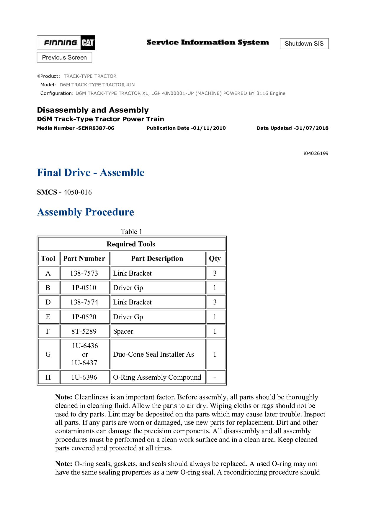
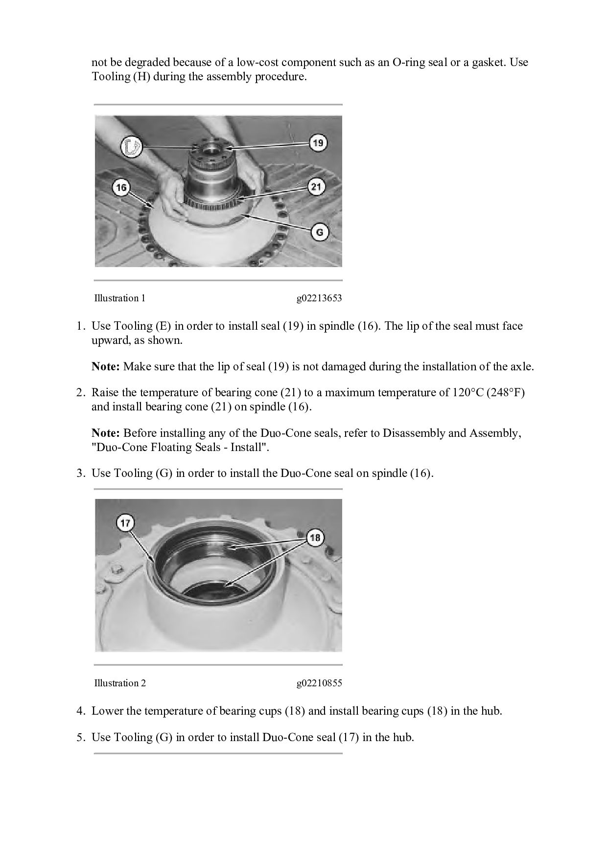
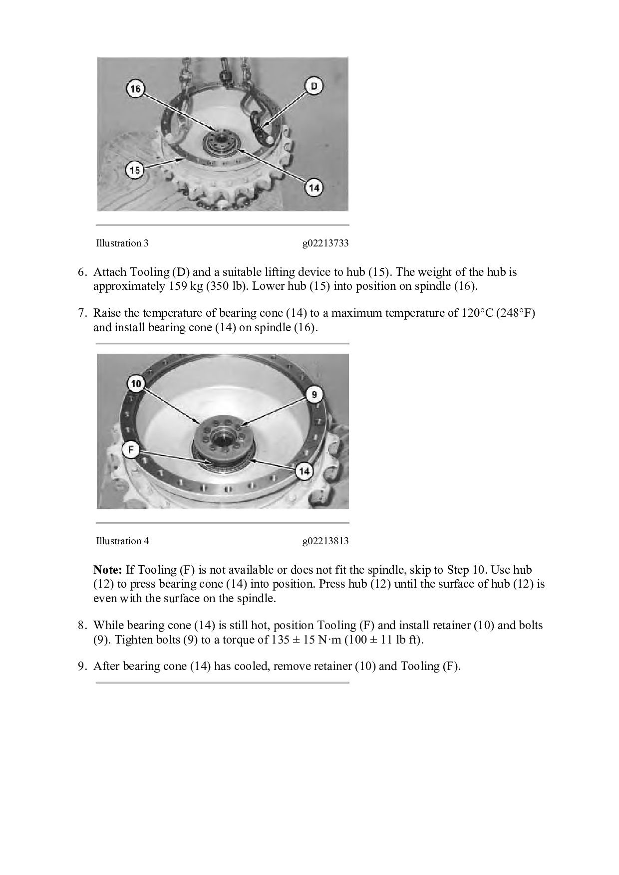
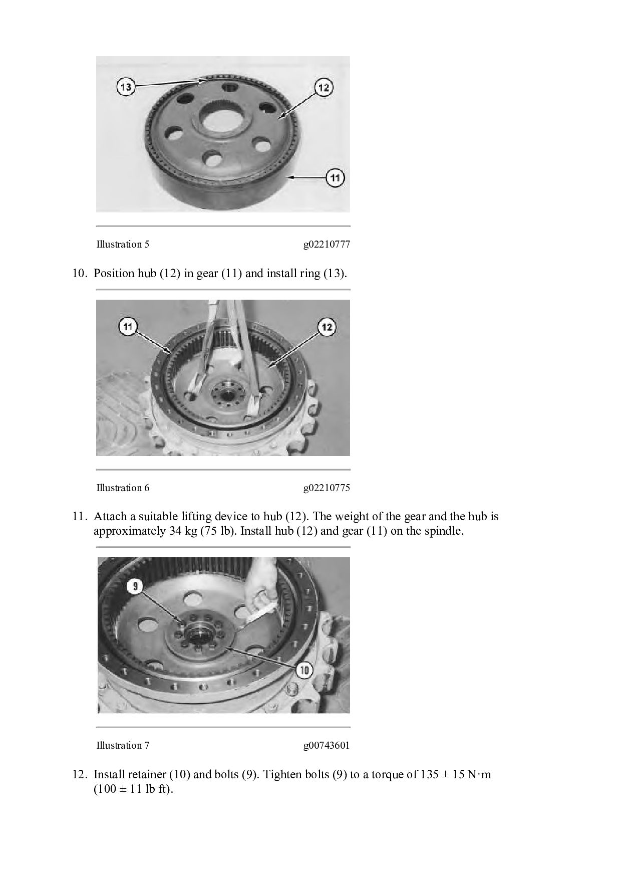
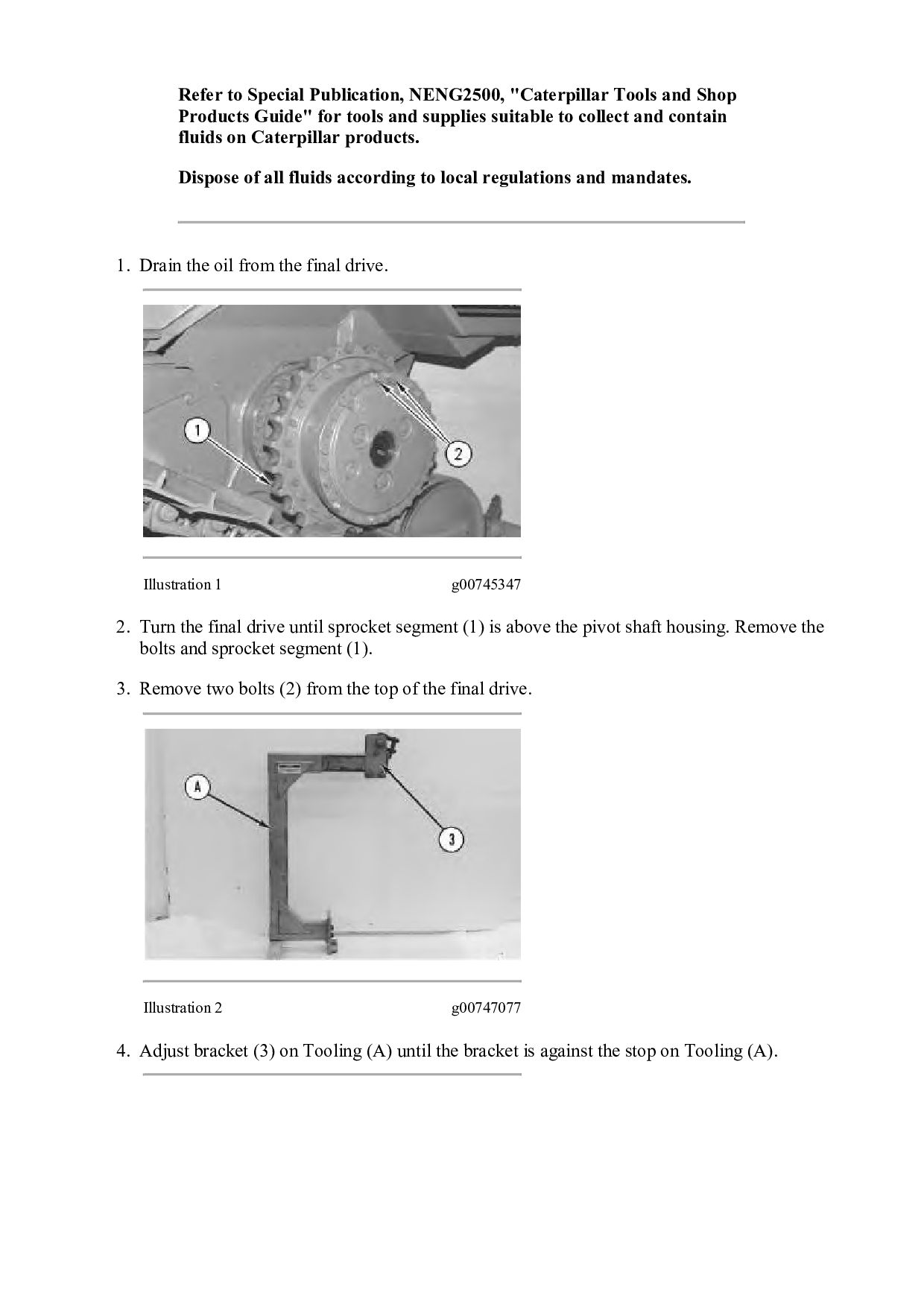
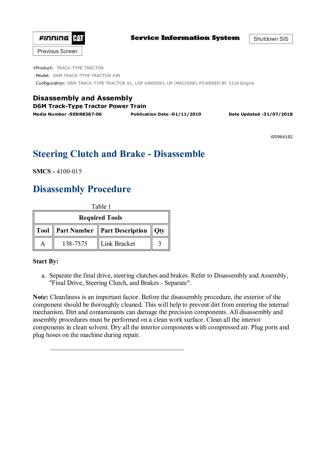
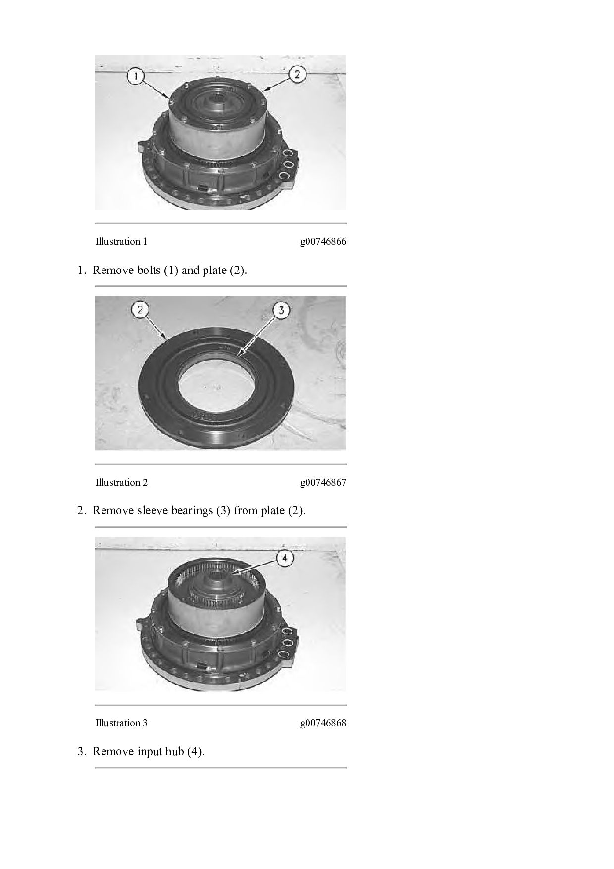
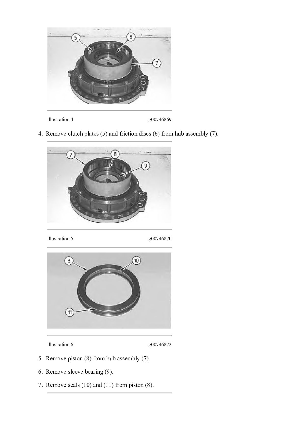
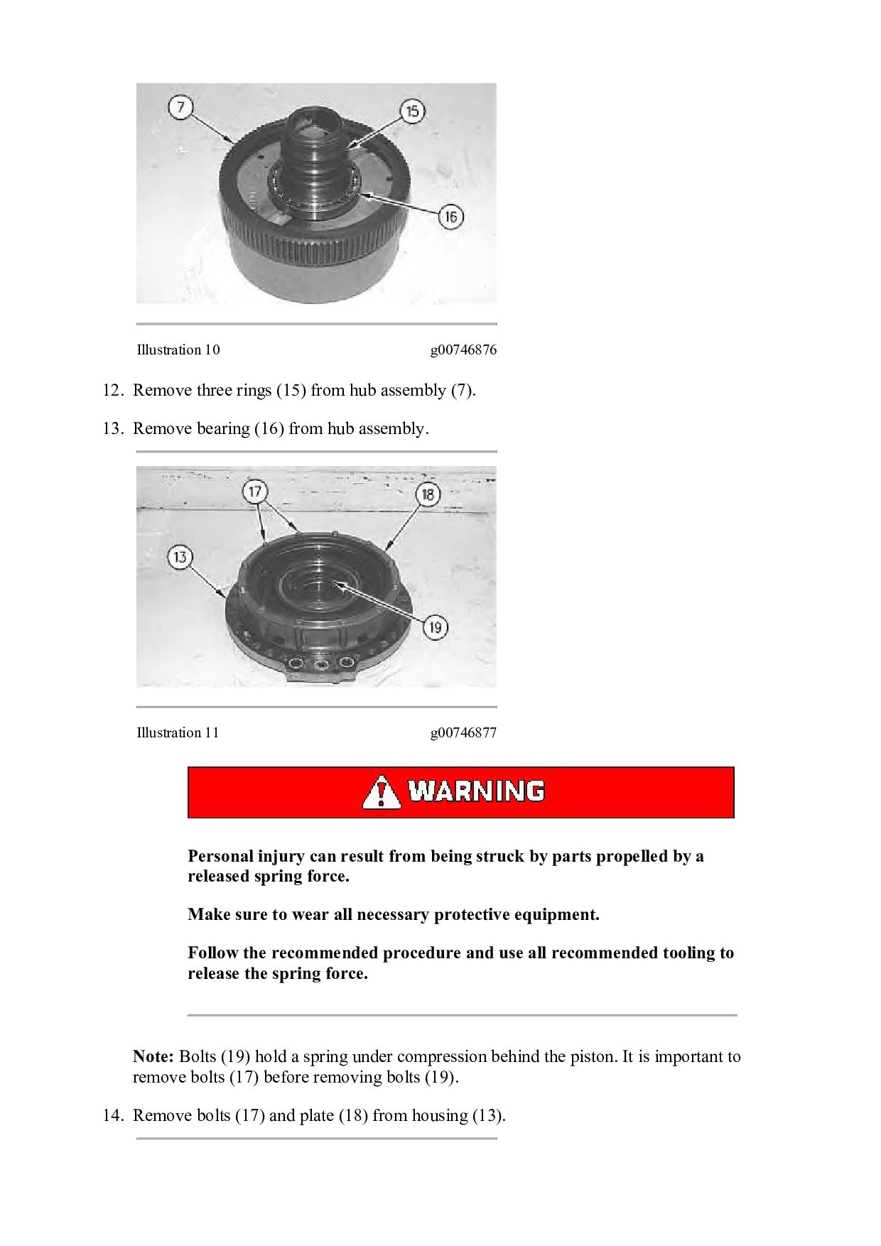
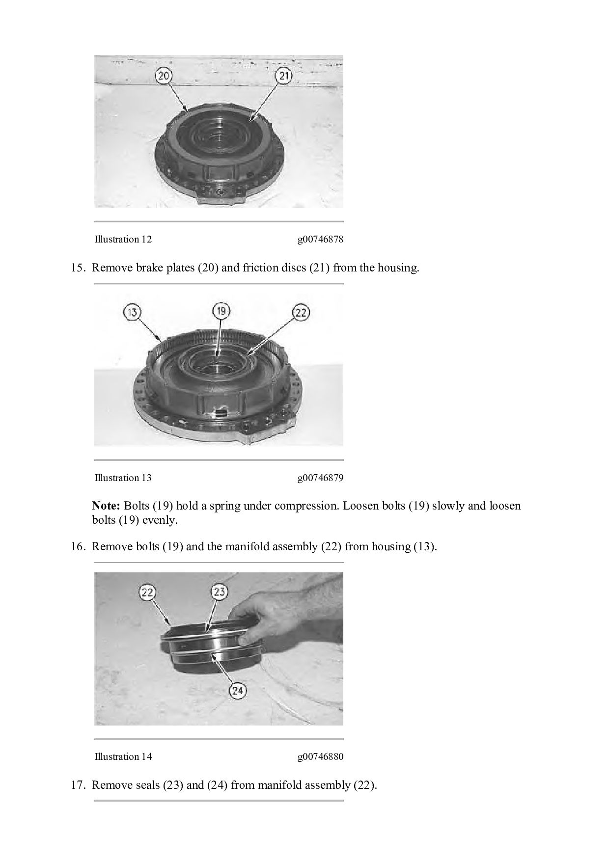
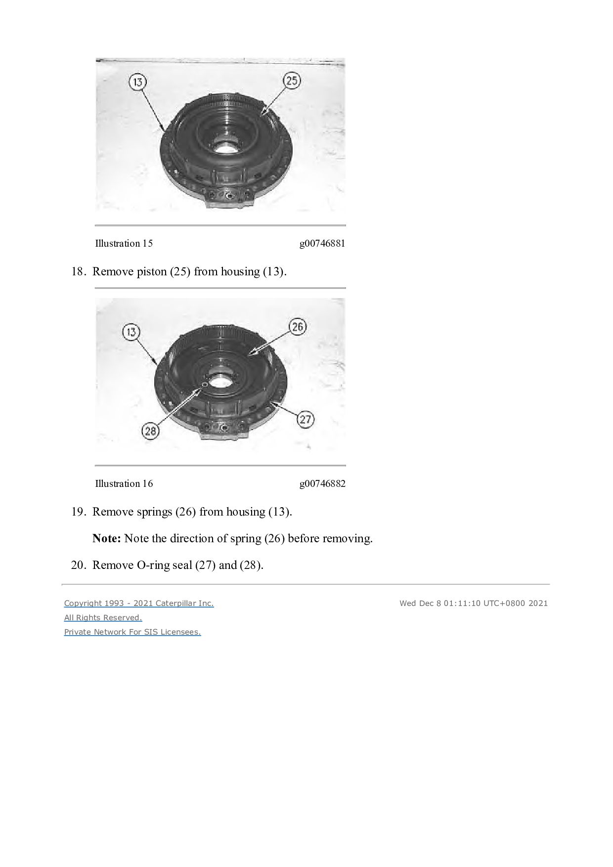
TRACTOR 4JN Configuration: D6M TRACK-TYPE TRACTOR XL, LGP 4JN00001-UP (MACHINE) POWERED BY 3116 Engine Disassembly and Assembly D6M Track-Type Tractor Power Train Media Number -SENR8387-06 Publication Date -01/11/2010 Date Updated -31/07/2018 i00964182 Steering Clutch and Brake - Disassemble SMCS - 4100-015 Disassembly Procedure Table 1 Required Tools Tool Part Number Part Description Qty A 138-7575 Link Bracket 3 Start By: a. Separate the final drive, steering clutches and brakes. Refer to Disassembly and Assembly, "Final Drive, Steering Clutch, and Brakes - Separate". Note: Cleanliness is an important factor. Before the disassembly procedure, the exterior of the component should be thoroughly cleaned. This will help to prevent dirt from entering the internal mechanism. Dirt and contaminants can damage the precision components. All disassembly and assembly procedures must be performed on a clean work surface. Clean all the interior components in clean solvent. Dry all the interior components with compressed air. Plug ports and plug hoses on the machine during repair.
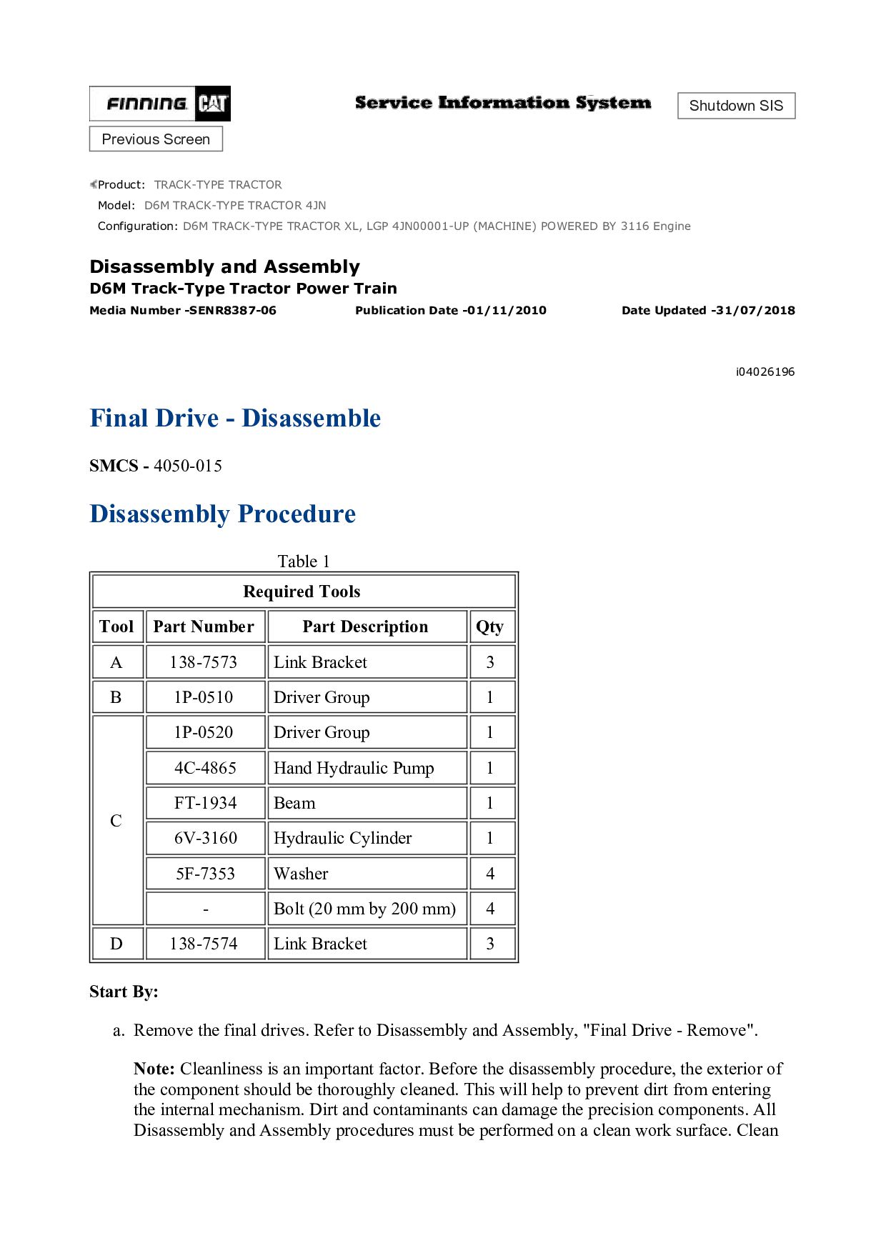
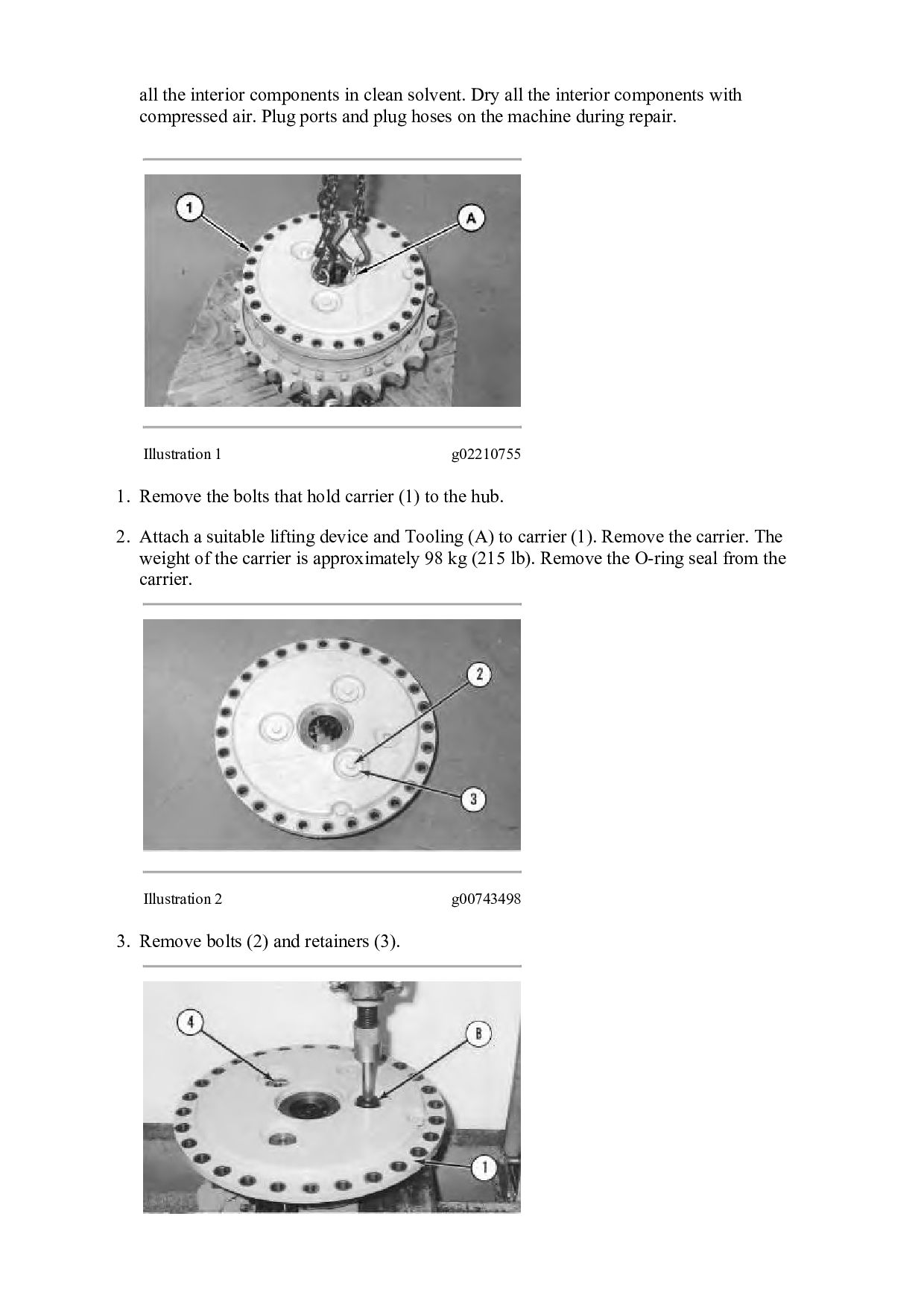
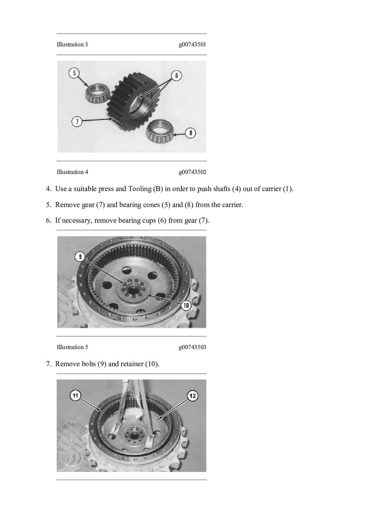
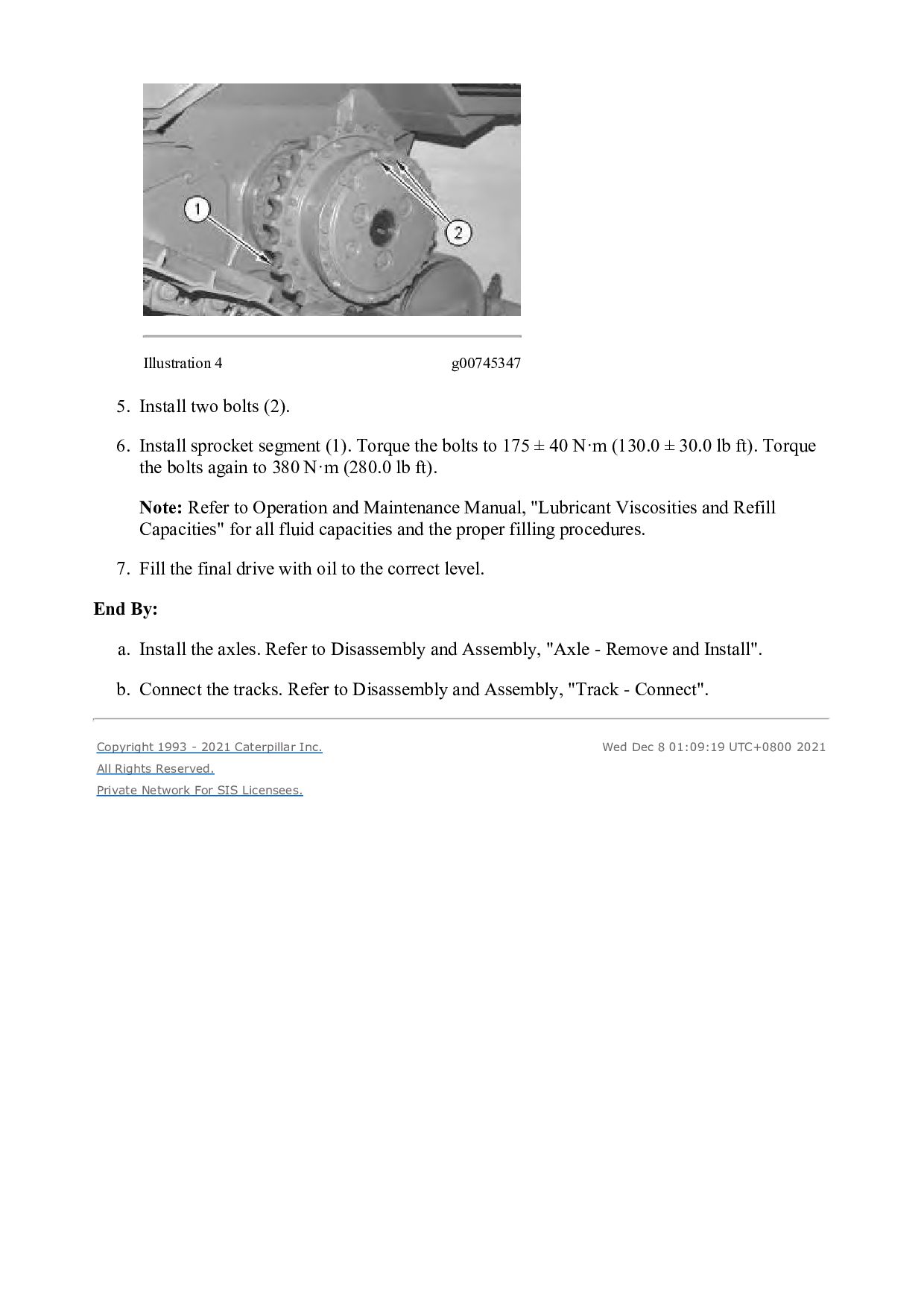
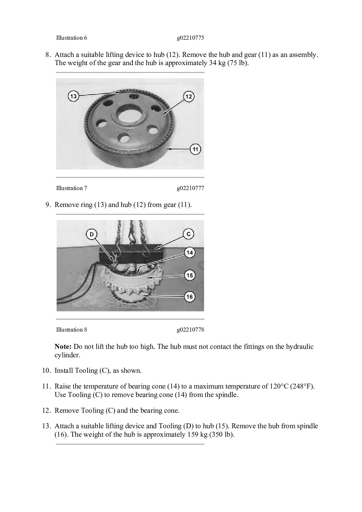
![Please write to us. Our email: [email protected] Please go to](https://files.speakerdeck.com/presentations/177e9aed9eb045718a92be52d1d28d7f/slide_25.jpg)