Upgrade to Pro — share decks privately, control downloads, hide ads and more …

Capturing Lightning

Capturing Lightning

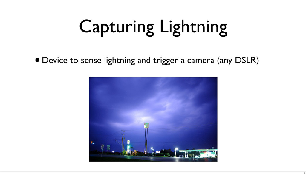
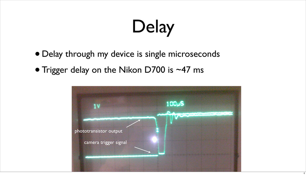
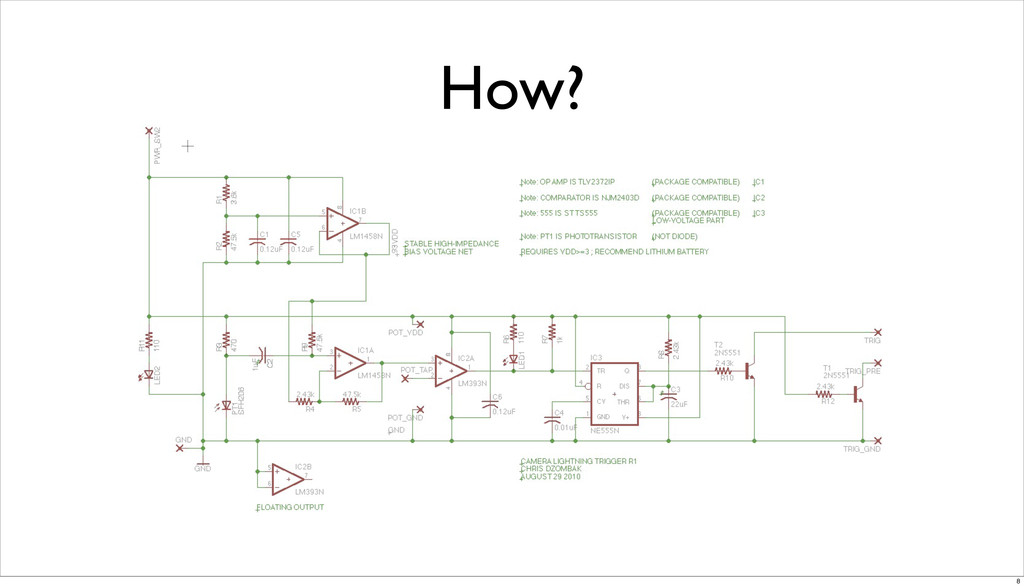
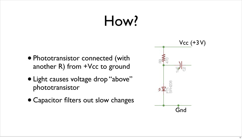
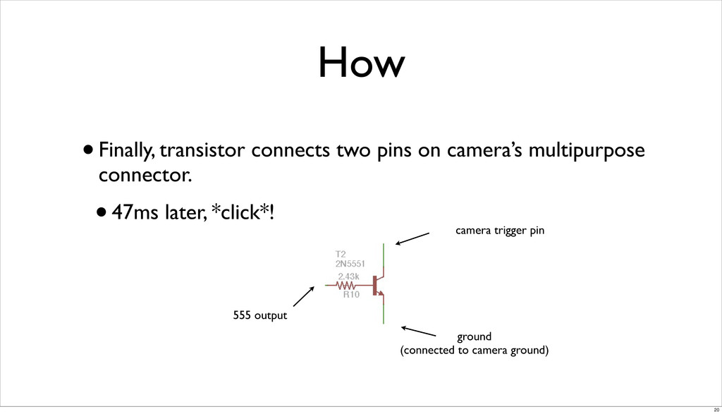
I built an analog circuit to trigger a DSLR camera when it detected lightning. I was invited to speak about it for an informal gathering of Michigan Engineering students.

There is no video, but you can download my slides: http://chris.dzombak.name/talks/pdf/2011-10-capturing-lightning.pdf

This talk appears on my site: http://chris.dzombak.name/talks/2011-10-capturing-lightning.html

Chris Dzombak

October 18, 2011
Tweet

More Decks by Chris Dzombak

Other Decks in Technology

Transcript

  1. Capturing Lightning
    Chris Dzombak
    @cdzombak
    for the Haus Series
    2011-10-18
    1

    View Slide

  2. About Me
    •CSE senior
    • formerly CE
    •Software developer at Nutshell
    • Android, JS/JQuery, HTML, CSS3, PHP, MySQL
    •Hobbies: photography, lighting design, journalism
    •And making cool stuff
    2

    View Slide

  3. Capturing Lightning
    •Device to sense lightning and trigger a camera (any DSLR)
    3

    View Slide

  4. Accomplishments
    •Reliably senses barely-visible test flashes
    •Triggers camera
    •Microsecond-order delay
    •Not much real-world testing yet (scheduling issues)
    4

    View Slide

  5. Lightning
    •Lightning strikes composed of several individual “strokes”
    •Spaced tens of milliseconds apart
    •Strokes are microseconds long
    •On average; stats vary widely
    •http://www.youtube.com/watch?v=dukkO7c2eUE
    5

    View Slide

  6. Delay
    •Delay through my device is single microseconds
    •Trigger delay on the Nikon D700 is ~47 ms
    phototransistor output
    camera trigger signal
    6

    View Slide

  7. So, in theory, it works.
    7

    View Slide

  8. How?
    8

    View Slide

  9. How?
    •Simple.
    •Phototransistor → Capacitor → Op Amp → Comparator →
    Trigger (555 + transistor)
    •And some LEDs indicate status
    9

    View Slide

  10. How?
    •Phototransistor connected (with
    another R) from +Vcc to ground
    •Light causes voltage drop “above”
    phototransistor
    •Capacitor filters out slow changes
    Vcc (+3 V)
    Gnd
    10

    View Slide

  11. How?
    •Op amp amplifies these fast light-
    level changes (voltage drops)
    •Pretty high gain, chosen
    experimentally
    •Currently about 20
    input from phototransistor/capacitor
    11

    View Slide

  12. Aside: Biasing the Op Amp
    •Op amps need +Vcc and -Vcc
    •But we only have 0 and 3V!
    •Solution: connect op amp’s -Vcc to ground
    •+Vcc is still +3 V
    12

    View Slide

  13. Aside: Biasing the Op Amp
    •Op amp can now drive 0 V to 3 V
    •Side note: Chose rail-to-rail op amp
    •Need to “bias” our input so “zero” value is between 0 and 3 V
    •Unlike EECS215 circuits
    13

    View Slide

  14. Aside: Biasing the Op Amp
    •We know input to the op amp will be driven lower, not higher
    •don’t care if it goes high
    •Use voltage divider to get 0.93 × Vcc
    •Buffer through another op amp for high impedance
    14

    View Slide

  15. Aside: Biasing the Op Amp
    Vcc (+3 V)
    Gnd
    stable, high-impedance
    bias voltage: 0.93Vcc
    capacitors ensure Vcc and
    Gnd nets stay stable
    15

    View Slide

  16. input from phototransistor/capacitor
    Aside: Biasing the Op Amp
    bias voltage net
    The rest of this
    should look
    familiar from
    EECS215.
    16

    View Slide

  17. How?
    •Comparator takes two signals
    •Outputs 1 if a•Potentiometer across Vcc/Gnd lets user choose a threshold
    •In practice, this is probably unnecessary
    17

    View Slide

  18. How?
    •Comparator compares op amp
    output to sensitivity chosen on
    potentiometer
    •Drives low if triggered; high
    otherwise
    op amp
    output
    LED lights when
    triggered
    18

    View Slide

  19. How?
    •555 circuit drives a 50ms
    signal high to trigger camera
    •Can’t just drive camera from
    comparator; signal is too fast
    comparator
    output
    output
    19

    View Slide

  20. How
    •Finally, transistor connects two pins on camera’s multipurpose
    connector.
    •47ms later, *click*!
    555 output
    ground
    (connected to camera ground)
    camera trigger pin
    20

    View Slide

  21. Challenges
    •Testing
    • considering building a lightning simulator
    •Single-supply op amp
    • and other factors (choosing rail-to-rail amp, choosing a proper gain)
    •Low-voltage parts
    • most 555’s are 5V
    21

    View Slide

  22. Recommended Reading
    •TI - Op Amps for Everyone
    •Immensely useful: basics, analysis, single-supply, noise, active
    filter design
    •http://www.ti.com/lit/an/slod006b/slod006b.pdf
    22

    View Slide

  23. Questions?
    23

    View Slide