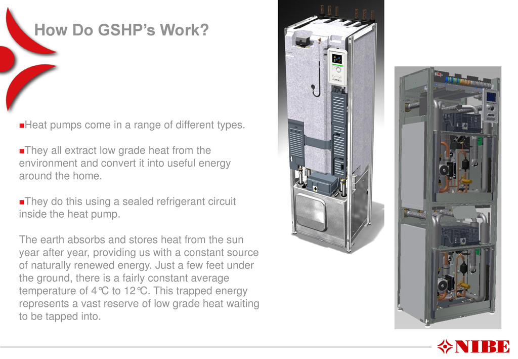
of different types. They all extract low grade heat from the environment and convert it into useful energy around the home. They do this using a sealed refrigerant circuit inside the heat pump. The earth absorbs and stores heat from the sun year after year, providing us with a constant source of naturally renewed energy. Just a few feet under the ground, there is a fairly constant average temperature of 4°C to 12°C. This trapped energy represents a vast reserve of low grade heat waiting to be tapped into.
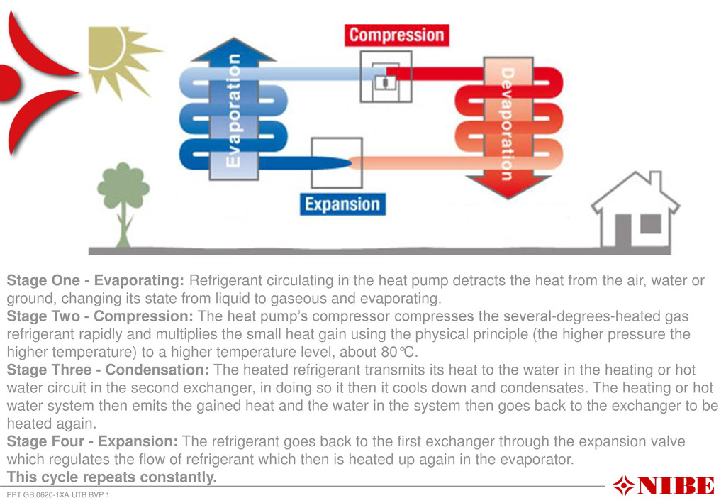
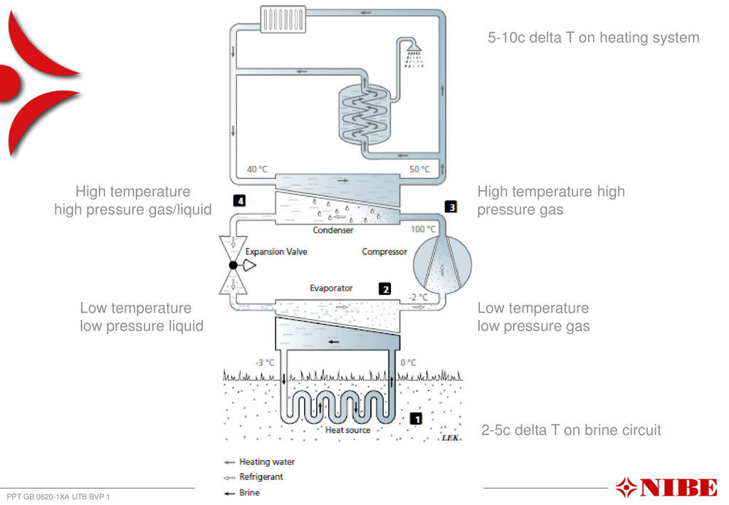
Refrigerant circulating in the heat pump detracts the heat from the air, water or ground, changing its state from liquid to gaseous and evaporating. Stage Two - Compression: The heat pump’s compressor compresses the several-degrees-heated gas refrigerant rapidly and multiplies the small heat gain using the physical principle (the higher pressure the higher temperature) to a higher temperature level, about 80°C. Stage Three - Condensation: The heated refrigerant transmits its heat to the water in the heating or hot water circuit in the second exchanger, in doing so it then it cools down and condensates. The heating or hot water system then emits the gained heat and the water in the system then goes back to the exchanger to be heated again. Stage Four - Expansion: The refrigerant goes back to the first exchanger through the expansion valve which regulates the flow of refrigerant which then is heated up again in the evaporator. This cycle repeats constantly.
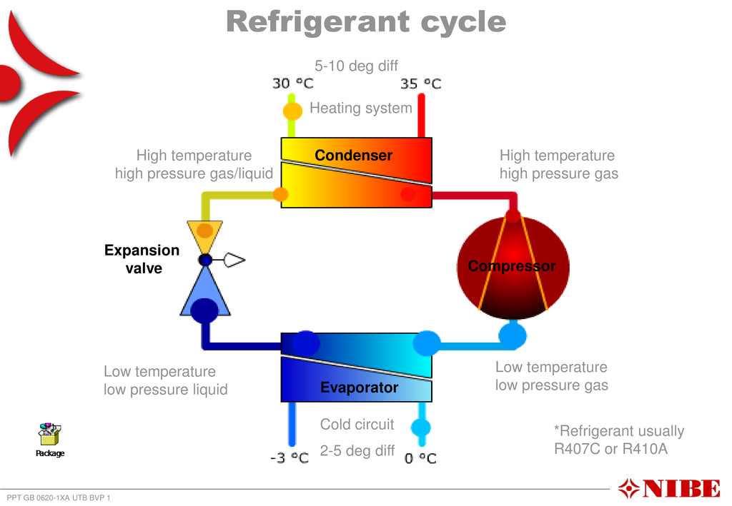
Compressor Condenser Evaporator Heating system Cold circuit 5-10 deg diff 2-5 deg diff Low temperature low pressure gas Low temperature low pressure liquid High temperature high pressure gas High temperature high pressure gas/liquid *Refrigerant usually R407C or R410A
heating system 2-5c delta T on brine circuit Low temperature low pressure gas Low temperature low pressure liquid High temperature high pressure gas/liquid High temperature high pressure gas
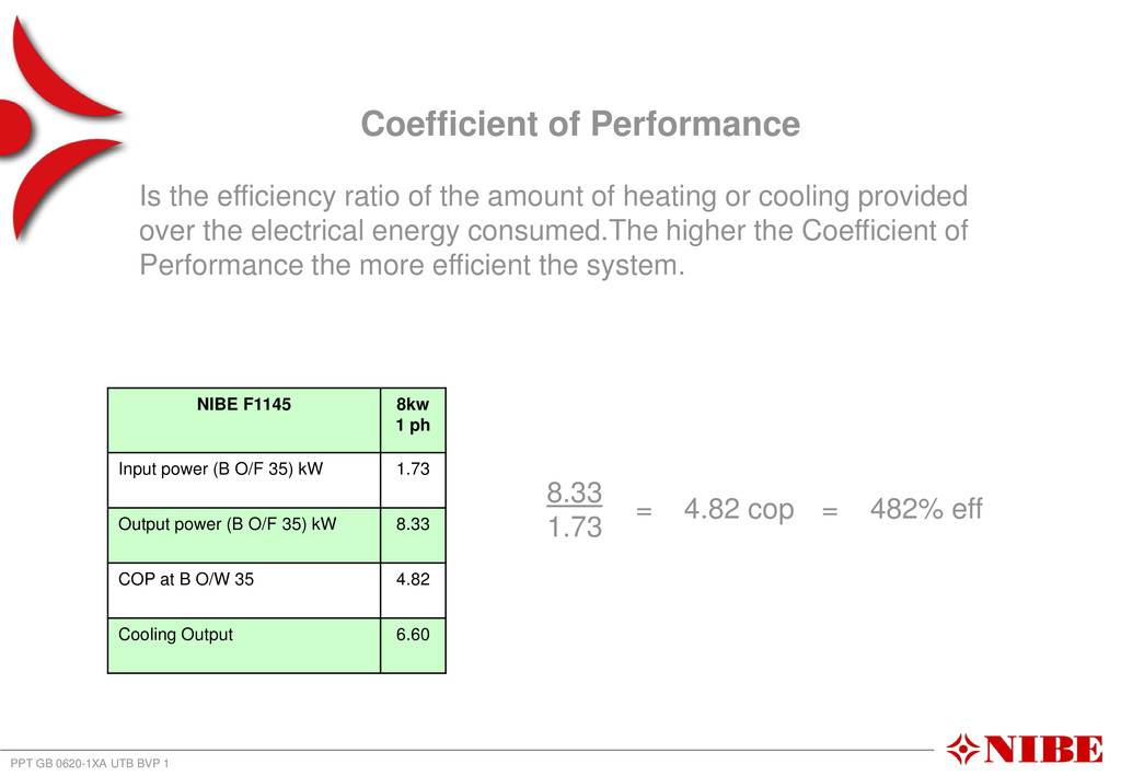
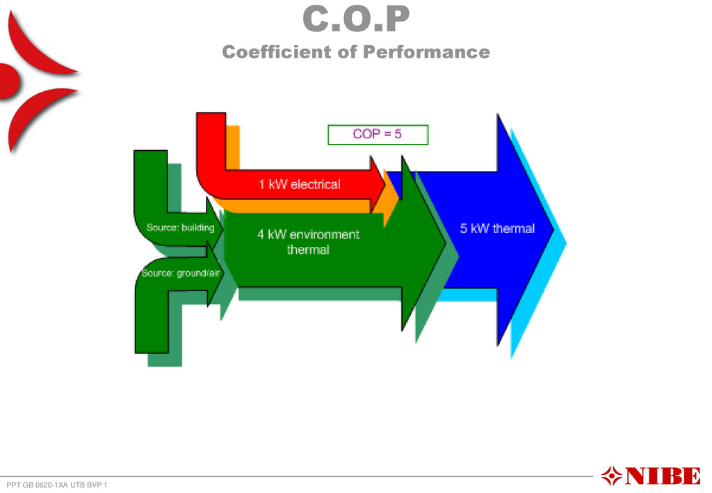
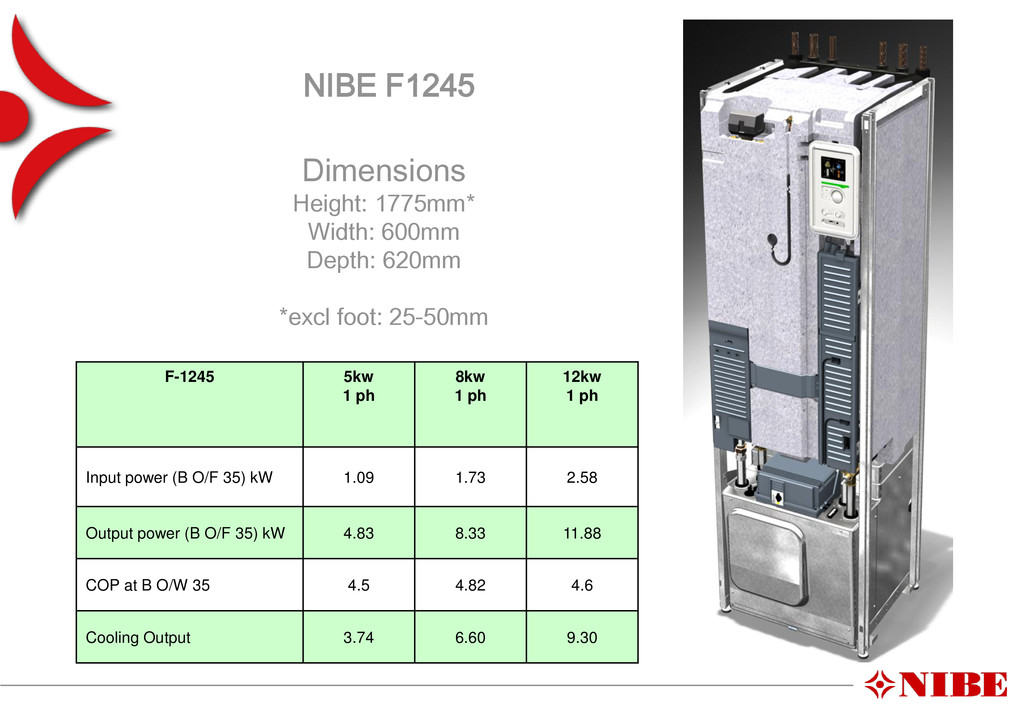
the efficiency ratio of the amount of heating or cooling provided over the electrical energy consumed.The higher the Coefficient of Performance the more efficient the system. NIBE F1145 8kw 1 ph Input power (B O/F 35) kW 1.73 Output power (B O/F 35) kW 8.33 COP at B O/W 35 4.82 Cooling Output 6.60 8.33 1.73 = 4.82 cop = 482% eff
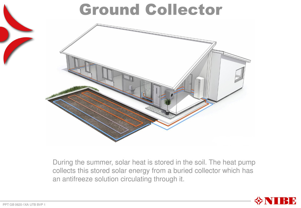
summer, solar heat is stored in the soil. The heat pump collects this stored solar energy from a buried collector which has an antifreeze solution circulating through it.
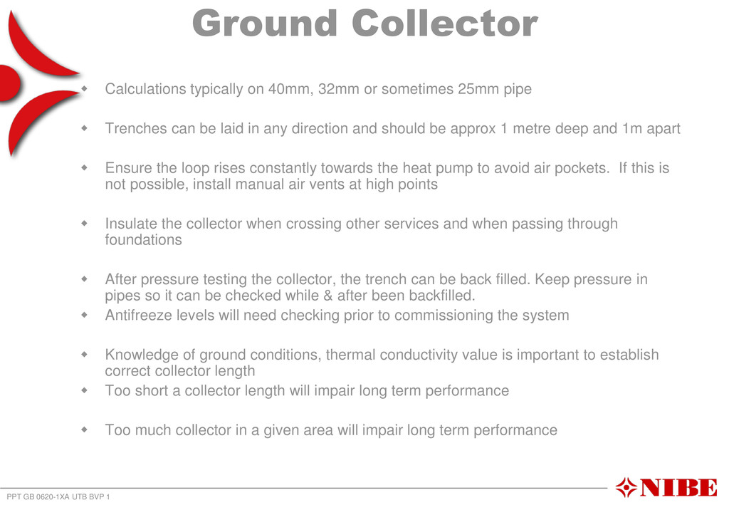
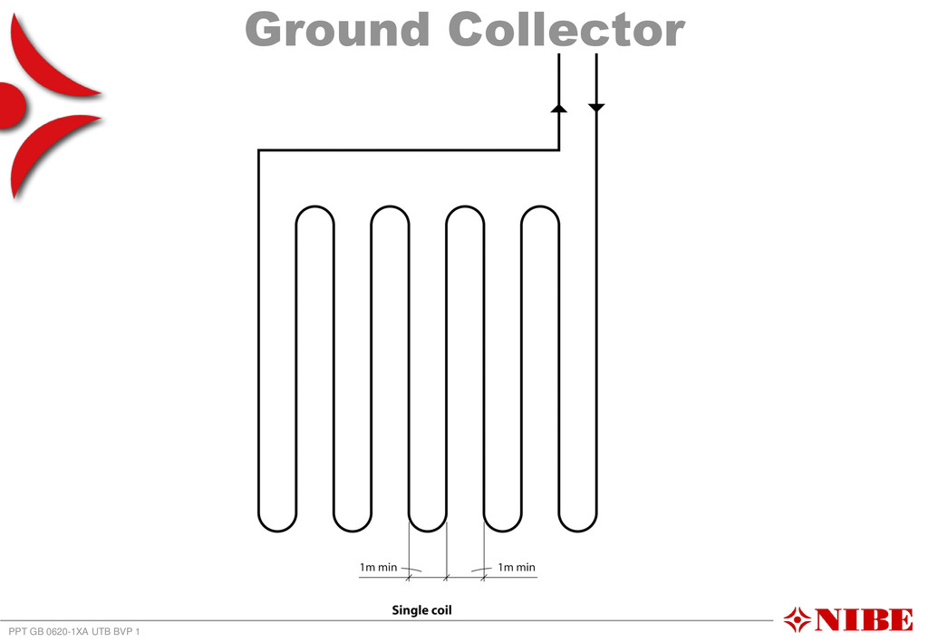
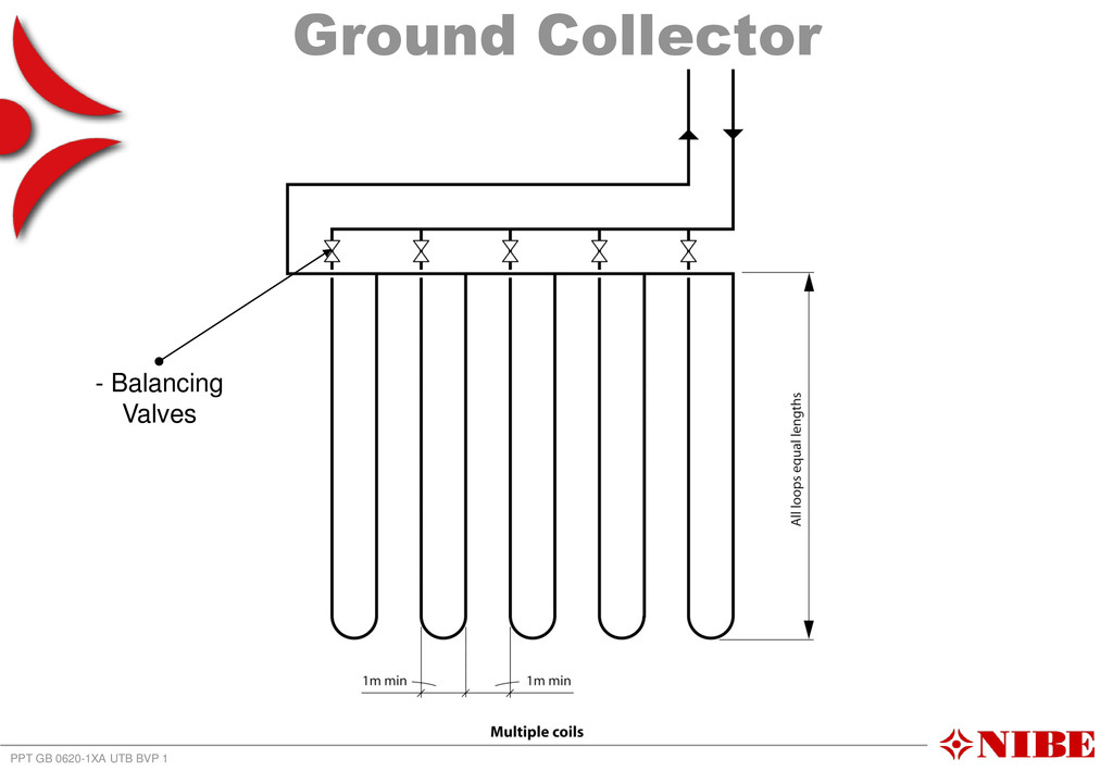
typically on 40mm, 32mm or sometimes 25mm pipe Trenches can be laid in any direction and should be approx 1 metre deep and 1m apart Ensure the loop rises constantly towards the heat pump to avoid air pockets. If this is not possible, install manual air vents at high points Insulate the collector when crossing other services and when passing through foundations After pressure testing the collector, the trench can be back filled. Keep pressure in pipes so it can be checked while & after been backfilled. Antifreeze levels will need checking prior to commissioning the system Knowledge of ground conditions, thermal conductivity value is important to establish correct collector length Too short a collector length will impair long term performance Too much collector in a given area will impair long term performance
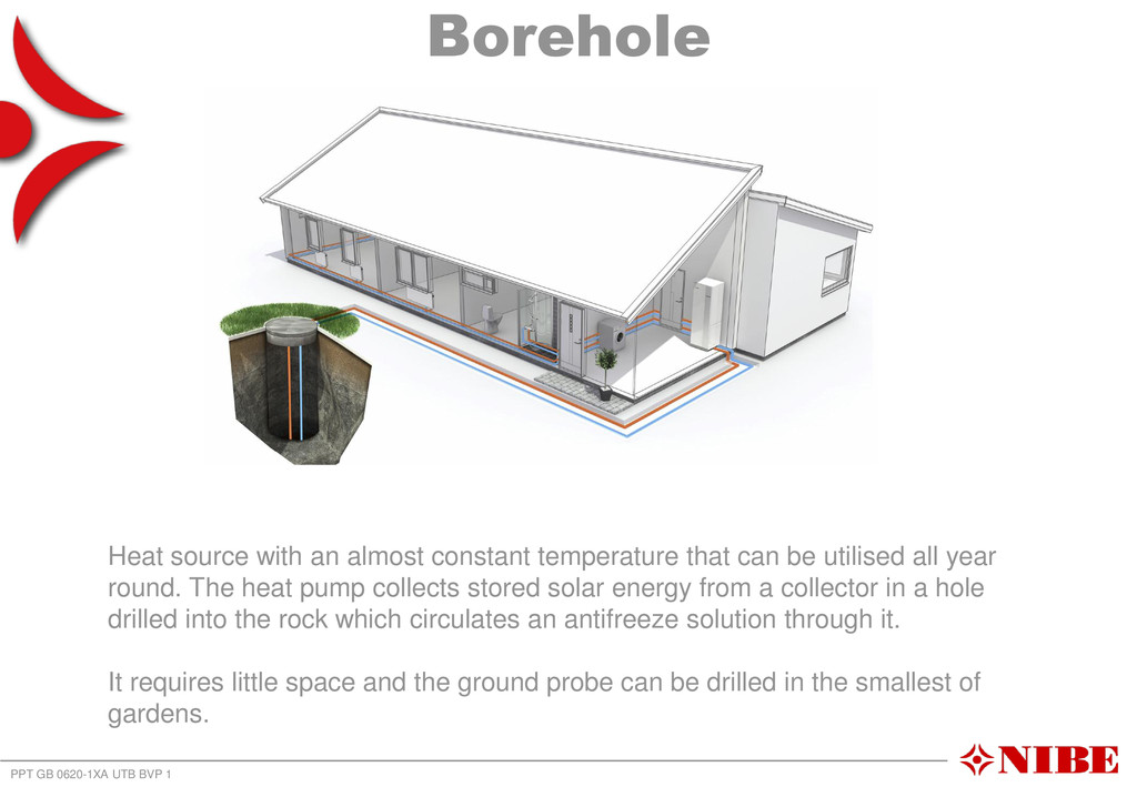
an almost constant temperature that can be utilised all year round. The heat pump collects stored solar energy from a collector in a hole drilled into the rock which circulates an antifreeze solution through it. It requires little space and the ground probe can be drilled in the smallest of gardens.
100-150m After the probe is lowered into the hole a mixture of bentonite grout is pumped in, the grout completely fills the hole. Knowledge of ground type and thermal conductivity required. Most GSHP drillers will carry out a survey Thermal response testing is a good way of assesing thermal conductivity, particularly on larger systems. Care needs to be taken when spacing boreholes Recommend fusion welded pipework below ground Usually considerably more expensive than a ground collector
system - comments Radiators or underfloor heating can be used. Consideration should be given to sizing of radiators to achieve a reasonable COP. Low heating flow temperatures gives an improved COP Systems often weather compensated for energy conservation Hot water cylinders must have coils rated for heat pumps to avoid issues with reliability and performance. Most heat pumps will be able to deliver between 55c-60c to a hot water cylinder. Average bathing temp is between 38c-42 so heat pump more than capable of achieving this. Consideration needs to be given to Legionella protection
for correct ground source heat pump system design Total heat load of building by way of a BS EN 12831 heat loss calculation. Total hot water requirements in accordance with BS 6700 Thermal conductivity of ground or borehole Flow temperature of heat emitter system either radiators or underfloor heating. Electricity supply available, amps, three phase or single phase etc. With these few pieces of info most GSHP installers and manufacturers would be able to determine whether a ground source heat pump is a viable option and select an appropriate product, however.......... **MIS 3005** must be adhered to in full when completing finalised design for a heat pump system as part of MCS certification
(MCS) is an independent scheme that certifies microgeneration products and installers in accordance with consistent standards. It is designed to evaluate microgeneration products and installers against robust criteria providing greater protection for consumers.
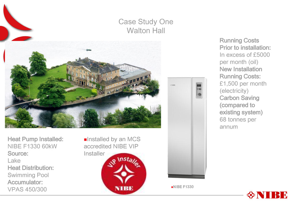
NIBE F1330 60kW Source: Lake Heat Distribution: Swimming Pool Accumulator: VPAS 450/300 Running Costs Prior to installation: In excess of £5000 per month (oil) New Installation Running Costs: £1,500 per month (electricity) Carbon Saving (compared to existing system) 68 tonnes per annum Installed by an MCS accredited NIBE VIP Installer
property set in acres of countryside. The client was not on mains gas and wanted a heating system that would be efficient, kind to the environment and, most importantly, cost effective PPT GB 0620-1XA UTB BVP 1 A three phase electricity supply was available, thereby, allowing for the use of a large single heat pump. Heat Pump: NIBE F1330-30kW Source:1800m MDPE Ground Collector Heat Distribution: Full Underfloor Heating Installed by a NIBE VIP Installer
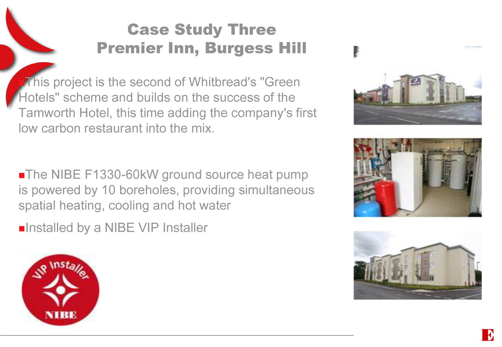
the second of Whitbread's "Green Hotels" scheme and builds on the success of the Tamworth Hotel, this time adding the company's first low carbon restaurant into the mix. The NIBE F1330-60kW ground source heat pump is powered by 10 boreholes, providing simultaneous spatial heating, cooling and hot water Installed by a NIBE VIP Installer
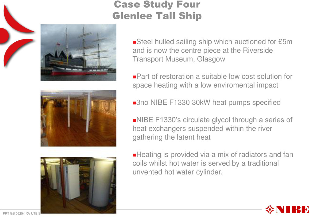
BVP 1 Steel hulled sailing ship which auctioned for £5m and is now the centre piece at the Riverside Transport Museum, Glasgow Part of restoration a suitable low cost solution for space heating with a low enviromental impact 3no NIBE F1330 30kW heat pumps specified NIBE F1330’s circulate glycol through a series of heat exchangers suspended within the river gathering the latent heat Heating is provided via a mix of radiators and fan coils whilst hot water is served by a traditional unvented hot water cylinder.