Conclusion Radiographic Views of the Skull Dr. Adegbenga Ismail Radiology Department University of Benin Teaching Hospital Benin City, Nigeria October 5th 2017 Dr. Adegbenga Ismail (UBTH) Radiographic Views of the Skull October 5th 2017 1 / 88
Conclusion Introduction Skull radiography involves the use of xrays to image the skull A good knowledge of the equipment, cranial anatomy and positioning landmarks is necessary in order to produce high quality images Dr. Adegbenga Ismail (UBTH) Radiographic Views of the Skull October 5th 2017 3 / 88
Conclusion Indications Head Trauma — with depressed or penetrating injury Foreign body within the skull Pathologies involving the bones Non-availability of Axial imaging Dr. Adegbenga Ismail (UBTH) Radiographic Views of the Skull October 5th 2017 4 / 88
Conclusion Limitations Difficult to interprete compared to axial imaging (due to complexity of the skull) Super-imposition of bone shadows; non-anatomical structures such as hair extensions, hair clips etc can make interpretation difficult Provides little or no information about the brain Dr. Adegbenga Ismail (UBTH) Radiographic Views of the Skull October 5th 2017 5 / 88
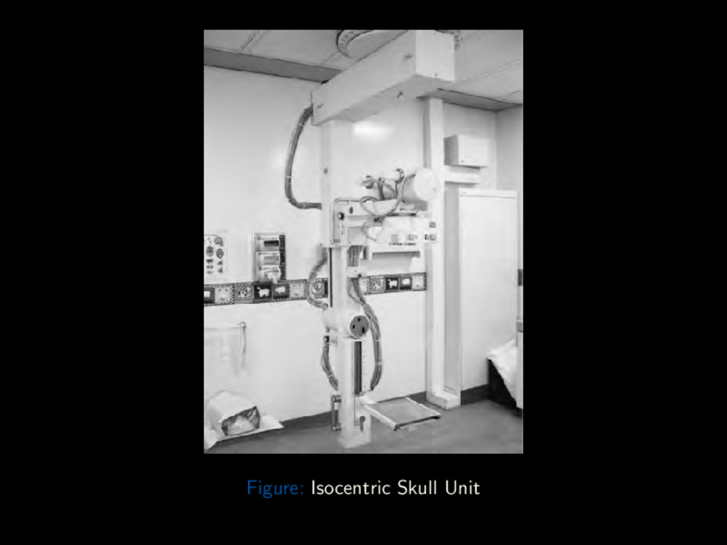
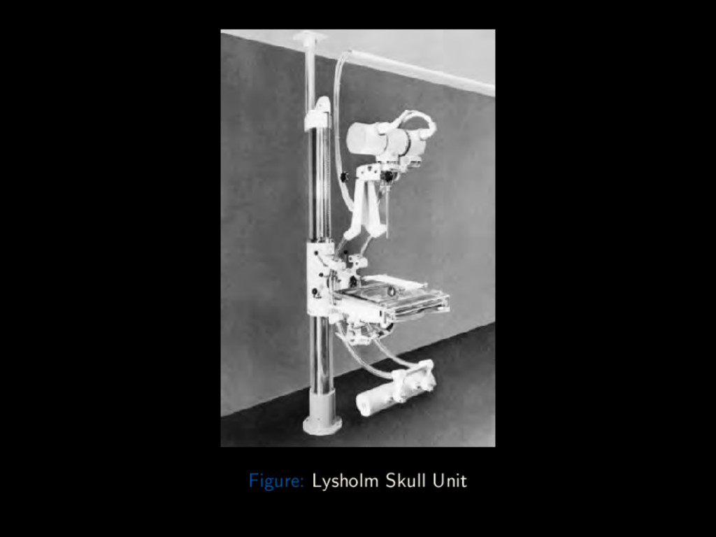
Conclusion Equipment General-purpose X-ray unit Special Skull Unit: 1 Isocentric Skull Unit 2 Lysholm Skull Unit Dr. Adegbenga Ismail (UBTH) Radiographic Views of the Skull October 5th 2017 6 / 88
Conclusion Special Skull Unit Advantages: Higher quality images than general purpose units Reduction in image distortion Higher resolution images (due to grid lattice and very fine anode focal spot) More accurate and consistent projections Better special collimators reduce scatter and secondary radiation to patients Dr. Adegbenga Ismail (UBTH) Radiographic Views of the Skull October 5th 2017 9 / 88
Conclusion Special Skull Unit Disadvantages: Expensive to purchase and maintain Can be lacking in versatility (esp for sick patients) May be unsuitable for uncooperative patients (due to narrow table) May require re-skilling of operators Dr. Adegbenga Ismail (UBTH) Radiographic Views of the Skull October 5th 2017 10 / 88
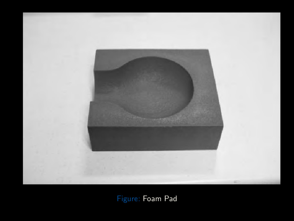
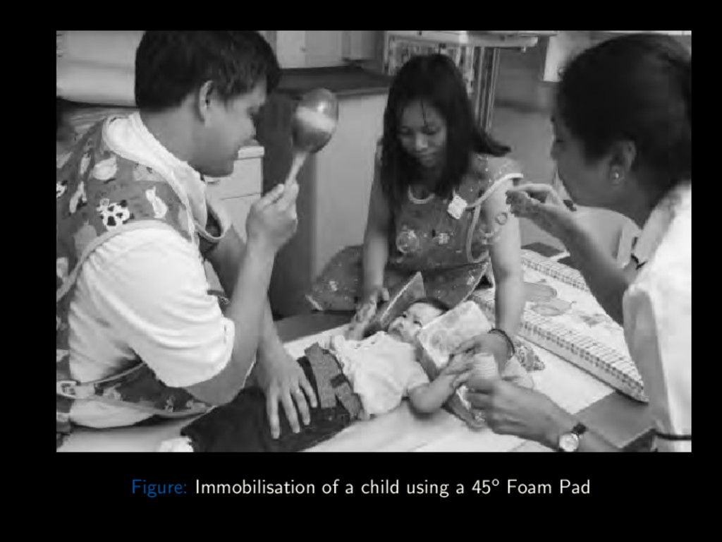
Conclusion Useful Accessories Foam pads 45o Triangular foam pads (for immobilising children) Side marker Lead protective apron Sand bag Dr. Adegbenga Ismail (UBTH) Radiographic Views of the Skull October 5th 2017 11 / 88
Conclusion Patient Preparation All metal and radio-opaque objects should be removed from patient (eg hair clips, pins etc) Pony-tails and bunches of hair should be loosened Metallic false teeth and metal dental bridges should be removed Dr. Adegbenga Ismail (UBTH) Radiographic Views of the Skull October 5th 2017 14 / 88
Conclusion General Technical Factors Patient positioning Erect Stable patient Quick and easy positioning Use of horizontal beam Supine Post head-trauma, ill-unstable patients Vertical beam Exposure Factors Exposure is done on arrested respiration Small focal spot Short exposure time Medium kV (65 – 75 kV film-screen) (70 – 80 kV CR and DDR) Grids are usually employed (to reduce scatter and improve resolution) SID of 1 to 1.1m is generally used. Dr. Adegbenga Ismail (UBTH) Radiographic Views of the Skull October 5th 2017 15 / 88
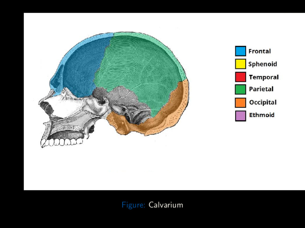
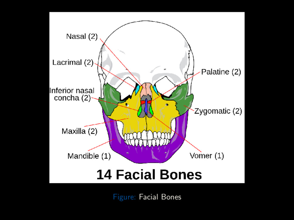
Conclusion Composition Skull is that part of the axial skeleton superior to the vertebral column. Houses and protects the brain Comprised of 22 separate bones: 8 Cranial bones (Calvarium) protects and houses the brain 1 Skull vault 2 Skull base 14 Facial bones provides structure, shape and support for the face. Also protects the eyes, upper respiratory and upper GI tracts Dr. Adegbenga Ismail (UBTH) Radiographic Views of the Skull October 5th 2017 16 / 88
Conclusion Skull Vault The skull vault comprises: 1 Frontal bone 1 Occipital bone 1 Right Parietal bone 1 Left Parietal bone Dr. Adegbenga Ismail (UBTH) Radiographic Views of the Skull October 5th 2017 17 / 88
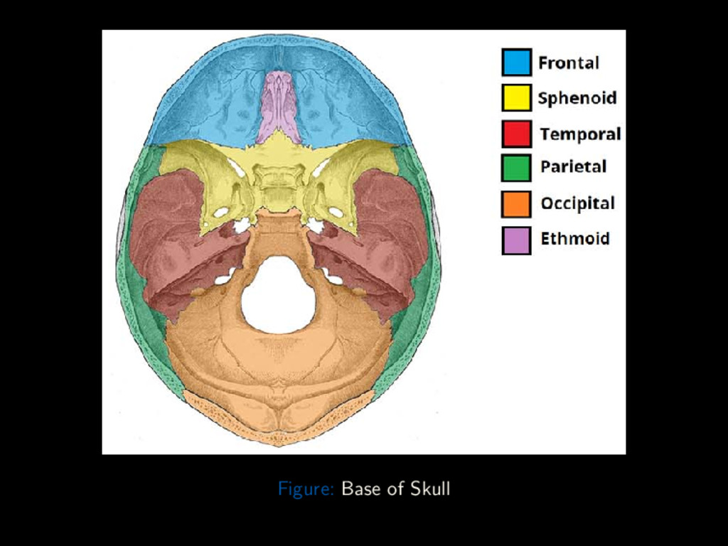
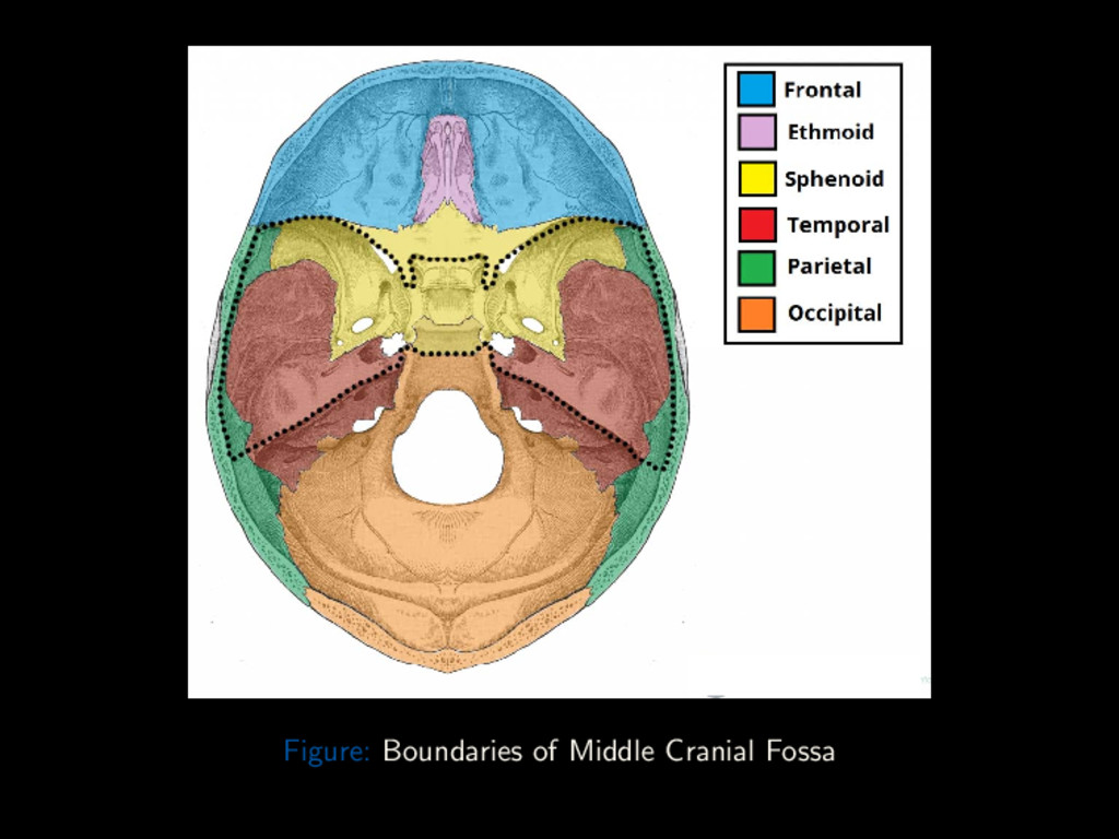
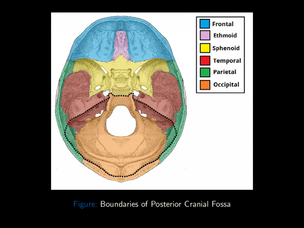
Conclusion Skull Base Base of the Skull is formed by: 1 ethmoid bone 1 sphenoid bone 1 Right Temporal bone 1 Left Temporal bone Dr. Adegbenga Ismail (UBTH) Radiographic Views of the Skull October 5th 2017 21 / 88
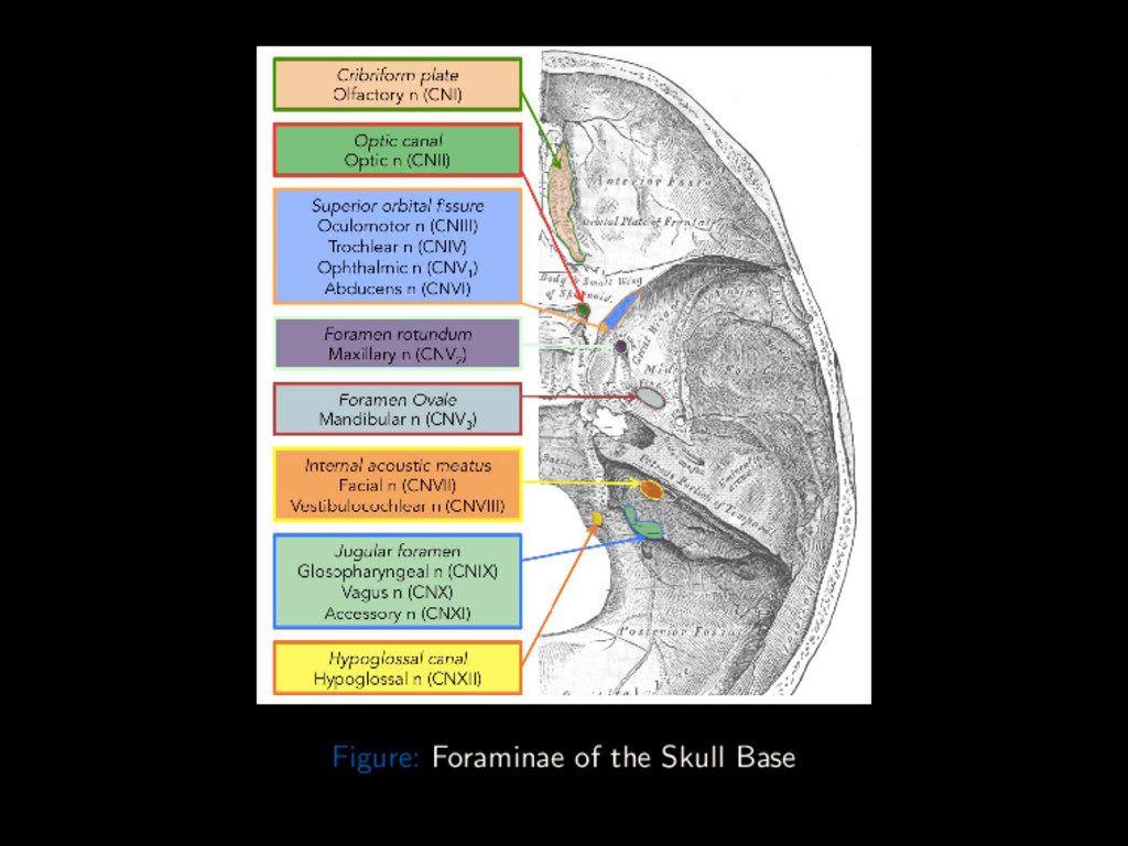
Conclusion Skull Base Foraminae Anterior Cranial Fossa: Foramen Cecum Emissary veins to superior sagittal sinus from upper part of the nose Anterior/Posterior Ethmoidal Foramen Anterior/Posterior Ethmoidal artery, vein and nerve Optic Canal Ophthalmic artery and Optic Nerve Dr. Adegbenga Ismail (UBTH) Radiographic Views of the Skull October 5th 2017 27 / 88
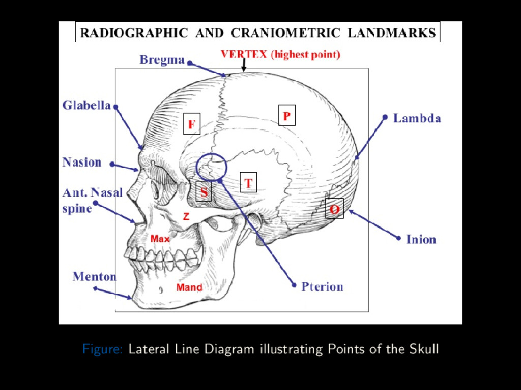
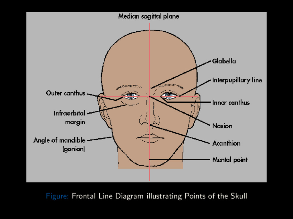
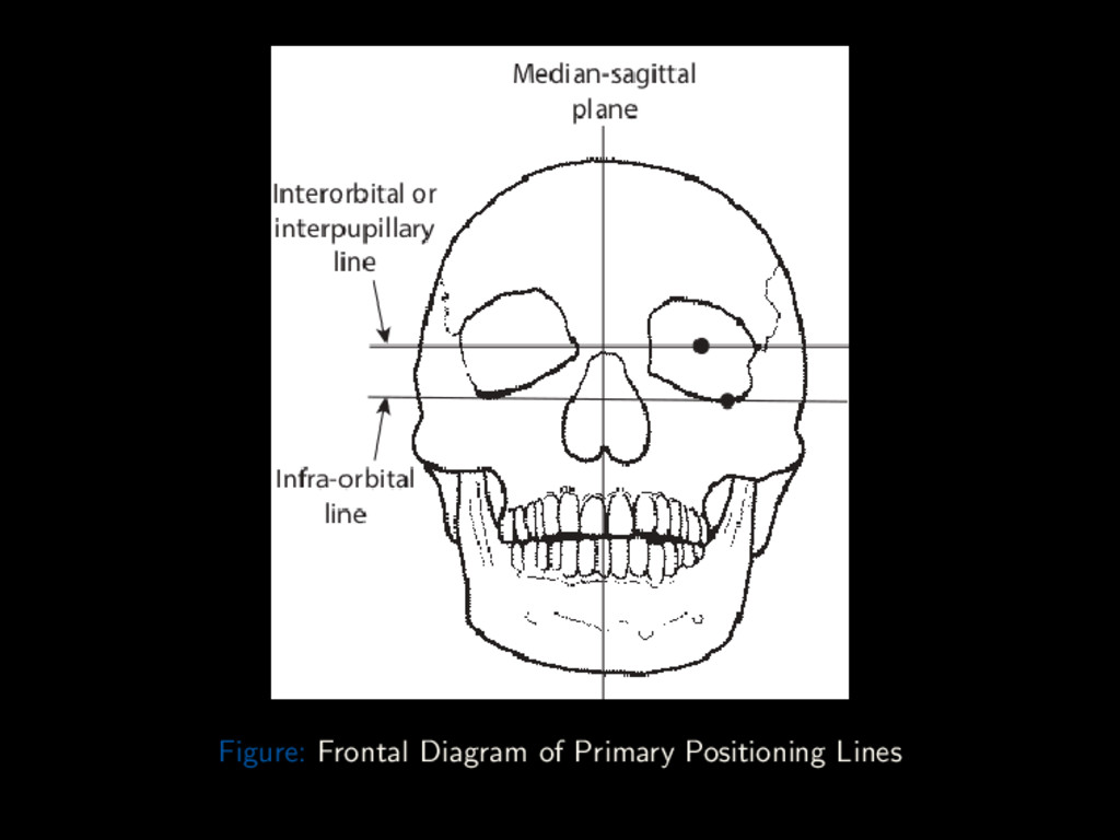
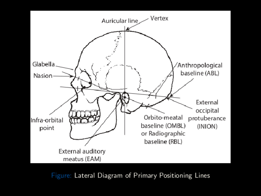
Conclusion Landmarks Outer Canthus of the Eye Lateral point where upper and lower eyelids meet Nasion Articulation of Nasal and Frontal bones Acanthion Tip of the anterior nasal spine Gonion Junction of lower border of ramus and body of mandible Glabella Bony prominence superior to Nasion Vertex Highest point of skull in Median Sagittal Plane External Occipital Protuberance (Inion) Bony prominence on occipital bone in Median Sagittal Plane External Auditory Meatus External opening of External Auditory Canal Dr. Adegbenga Ismail (UBTH) Radiographic Views of the Skull October 5th 2017 31 / 88
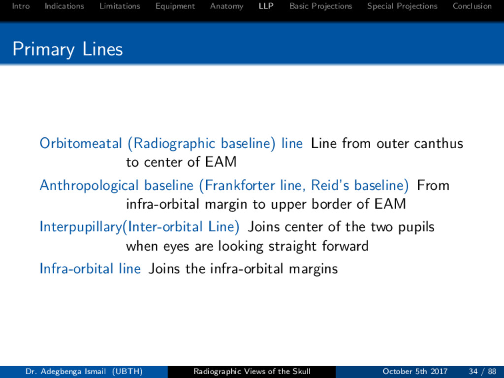
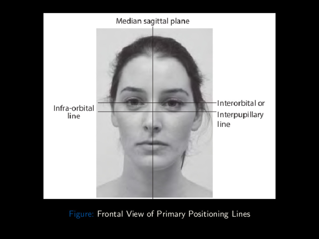
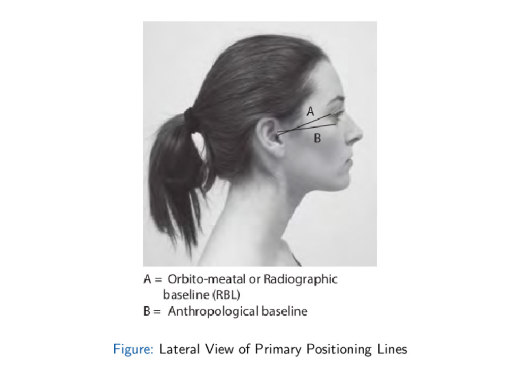
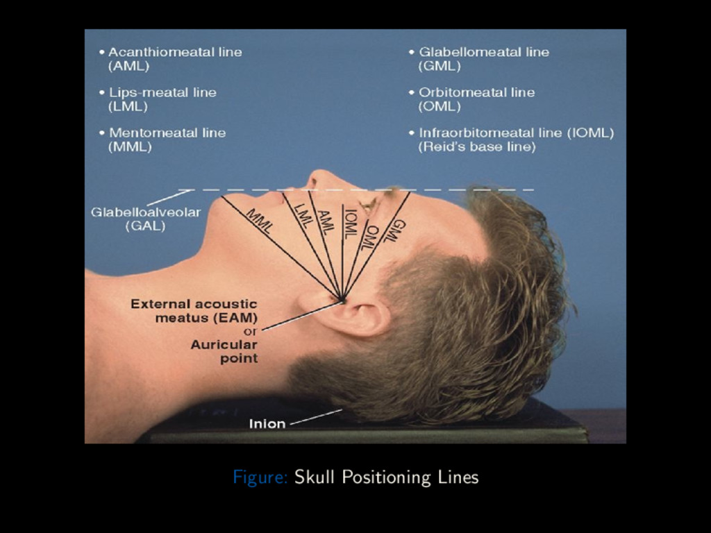
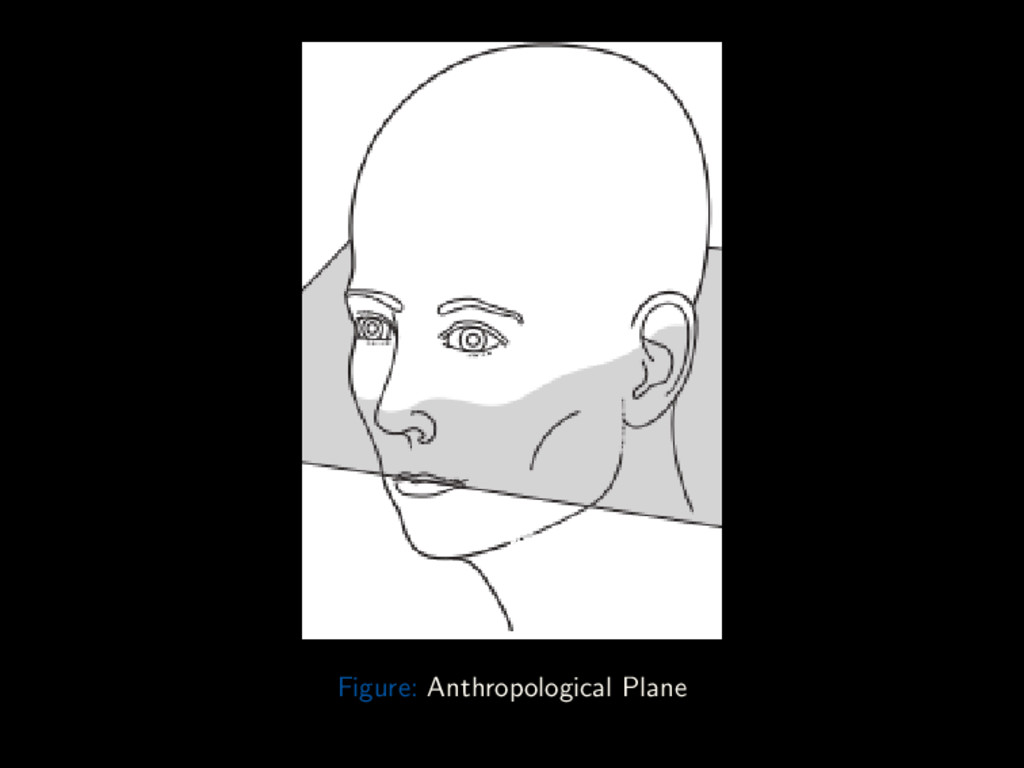
Conclusion Primary Lines Orbitomeatal (Radiographic baseline) line Line from outer canthus to center of EAM Anthropological baseline (Frankforter line, Reid’s baseline) From infra-orbital margin to upper border of EAM Interpupillary(Inter-orbital Line) Joins center of the two pupils when eyes are looking straight forward Infra-orbital line Joins the infra-orbital margins Dr. Adegbenga Ismail (UBTH) Radiographic Views of the Skull October 5th 2017 34 / 88
Conclusion Other Lines Glabellomeatal Line Line through the glabella and EAM Acanthiomeatal Line Line through the acanthion and EAM Lips-meatal Line Line through the angle of the lips and EAM Mentomeatal Line Line through the Mental point and EAM Glabelloalveolar Line Line through the glabella and alveolar process of the Maxilla Supra-orbitomeatal Line Line through the supra-orbital margin and the EAM Dr. Adegbenga Ismail (UBTH) Radiographic Views of the Skull October 5th 2017 39 / 88
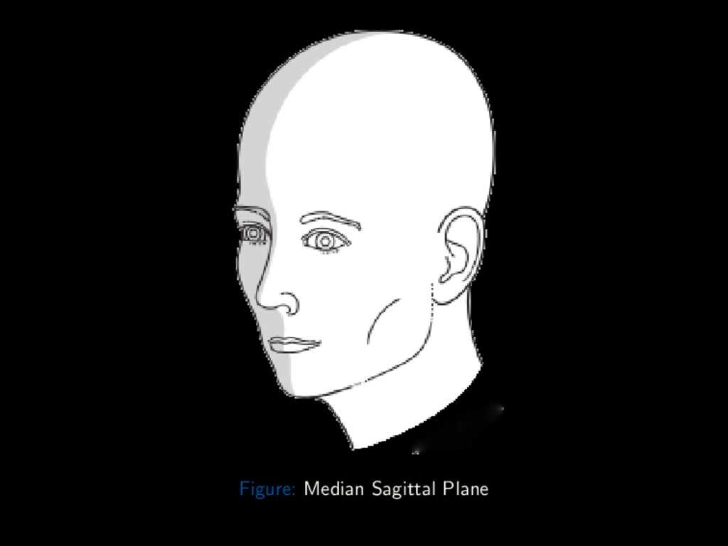
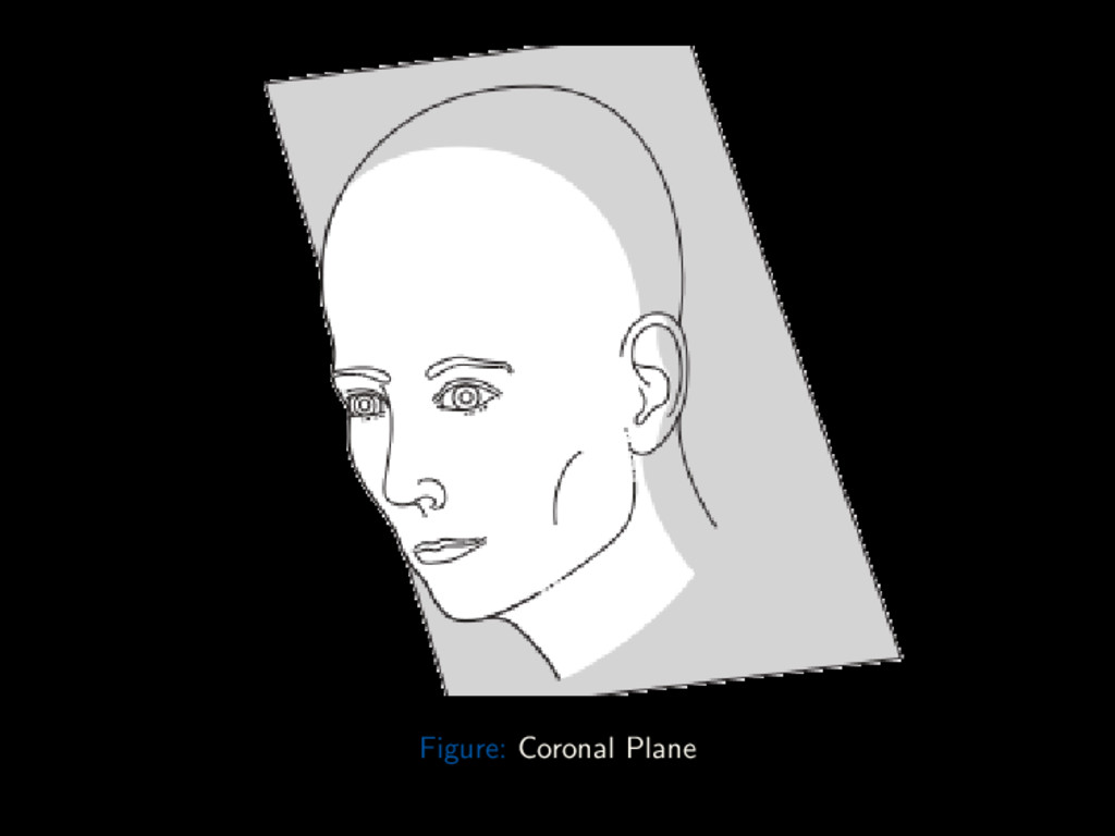
Conclusion Planes Median Sagittal Plane Plane divides the skull into two equal right and left halves. Landmarks are the nasion anteriorly and the external occipital protuberance (inion) posteriorly Coronal Plane Perpendicular to the median sagittal plane, divides the head into anterior and posterior parts Auricular plane An example of a coronal plane. Passes through the EAMs, perpendicular to the anthropological baseline Anthropological plane Plane through the anthropological baseline (example of Axial plane) Dr. Adegbenga Ismail (UBTH) Radiographic Views of the Skull October 5th 2017 41 / 88
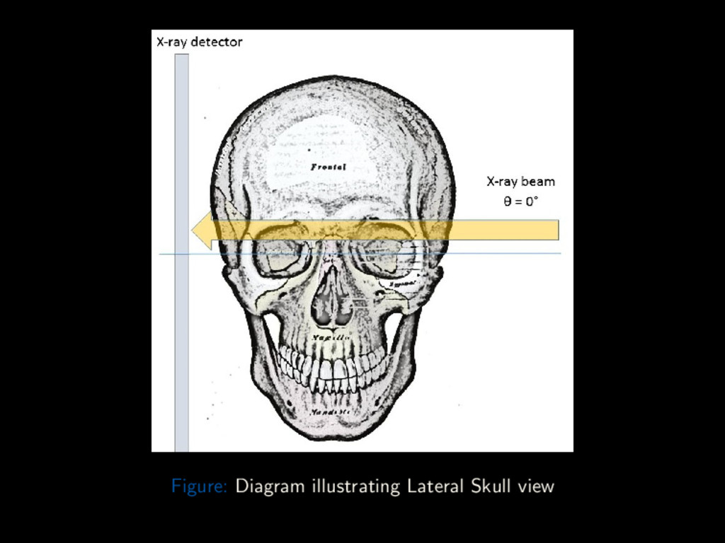
Conclusion Lateral The lateral skull view is a non-angled lateral radiograph of the skull. It provides an overview of the entire skull, rather than highlighting any one region. Cassette: 10 × 12” Cross-wise Grid Dr. Adegbenga Ismail (UBTH) Radiographic Views of the Skull October 5th 2017 46 / 88
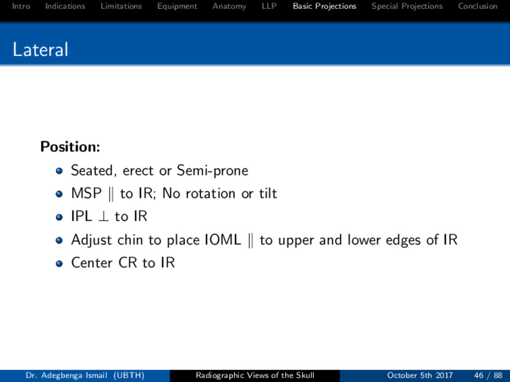
Conclusion Lateral Position: Seated, erect or Semi-prone MSP to IR; No rotation or tilt IPL ⊥ to IR Adjust chin to place IOML to upper and lower edges of IR Center CR to IR Dr. Adegbenga Ismail (UBTH) Radiographic Views of the Skull October 5th 2017 46 / 88
Conclusion Lateral Centring Point 5cm superior to EAM Central Ray CR is ⊥ to IR Collimation On four sides to skull margins Respiration Suspend during exposure Dr. Adegbenga Ismail (UBTH) Radiographic Views of the Skull October 5th 2017 46 / 88
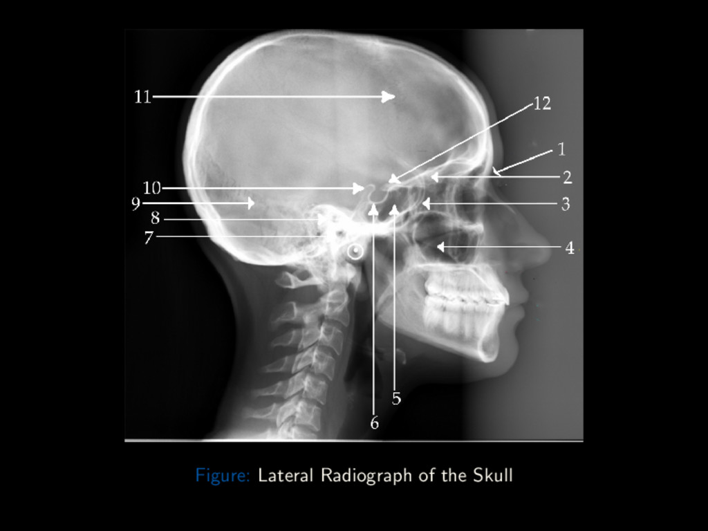
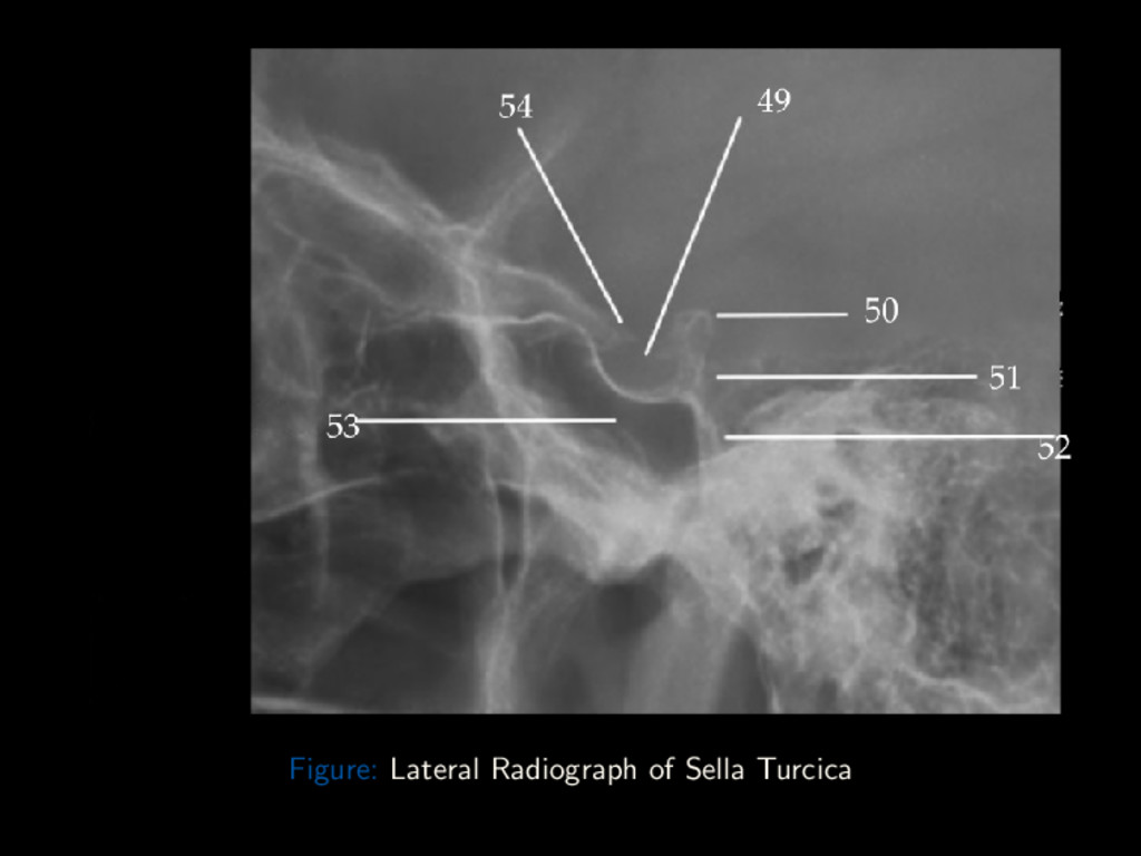
Conclusion Lateral – Critique Points Structures Shown: Super-imposed cranial halves Entire sella turcica and dorsum sellae Position: No tilt, evident by super-imposition of orbital plates (roofs) No rotation, evident by super-imposition of greater wings of sphenoid and mandibular rami Exposure: Optimal density and contrast to visualize sellar structures Sharp bony margins, no motion blur Dr. Adegbenga Ismail (UBTH) Radiographic Views of the Skull October 5th 2017 48 / 88
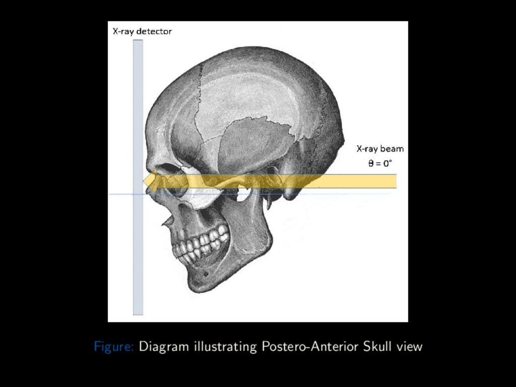
Conclusion Straight Posterior-Anterior The skull PA view is a non-angled PA radiograph of the skull. It provides an overview of the entire skull rather than attempting to highlight any one region. Cassette: 10 × 12” Length-wise Grid Dr. Adegbenga Ismail (UBTH) Radiographic Views of the Skull October 5th 2017 50 / 88
Conclusion Straight Posterior-Anterior Position: Seated, erect or Prone on table Nose and Forehead are in contact with the IR MSP and Orbito-meatal plane ⊥ to IR Center IR to projected CR Dr. Adegbenga Ismail (UBTH) Radiographic Views of the Skull October 5th 2017 50 / 88
Conclusion Straight Posterior-Anterior Centring Point External Occipital Protuberance Central Ray CR is ⊥ to IR, centered to exit at nasion Collimation On four sides to skull margins Dr. Adegbenga Ismail (UBTH) Radiographic Views of the Skull October 5th 2017 50 / 88
Conclusion PA – Critique Points Structures Shown: Frontal bone Crista galli Position: Petrous ridges, at level of superior orbital margins Lateral margin of orbits, is equidistant to lateral margin of skull Exposure: Optimum density and contrast to visualize frontal bone and surrounding structures Sharp bony margins, no motion blur Dr. Adegbenga Ismail (UBTH) Radiographic Views of the Skull October 5th 2017 52 / 88
Conclusion Inclined Posterior-Anterior (Caldwell) The Caldwell view is a caudally angled PA radiograph of the skull, designed to better visualise the frontal sinus. Cassette: 10 × 12” Length-wise Grid Dr. Adegbenga Ismail (UBTH) Radiographic Views of the Skull October 5th 2017 54 / 88
Conclusion Inclined Posterior-Anterior (Caldwell) Position: Seated, erect or Prone on table Nose and Forehead are in contact with the IR MSP and Orbito-meatal plane ⊥ to IR Center IR to projected CR Dr. Adegbenga Ismail (UBTH) Radiographic Views of the Skull October 5th 2017 54 / 88
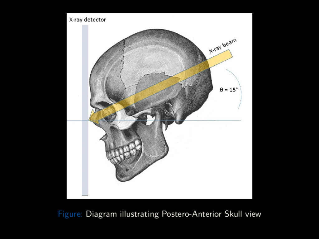
Conclusion Inclined Posterior-Anterior (Caldwell) Centring Point External Occipital Protuberance Central Ray CR is angled 15o caudad to the Orbito-meatal line. Centered to exit at nasion Collimation On four sides to skull margins Dr. Adegbenga Ismail (UBTH) Radiographic Views of the Skull October 5th 2017 54 / 88
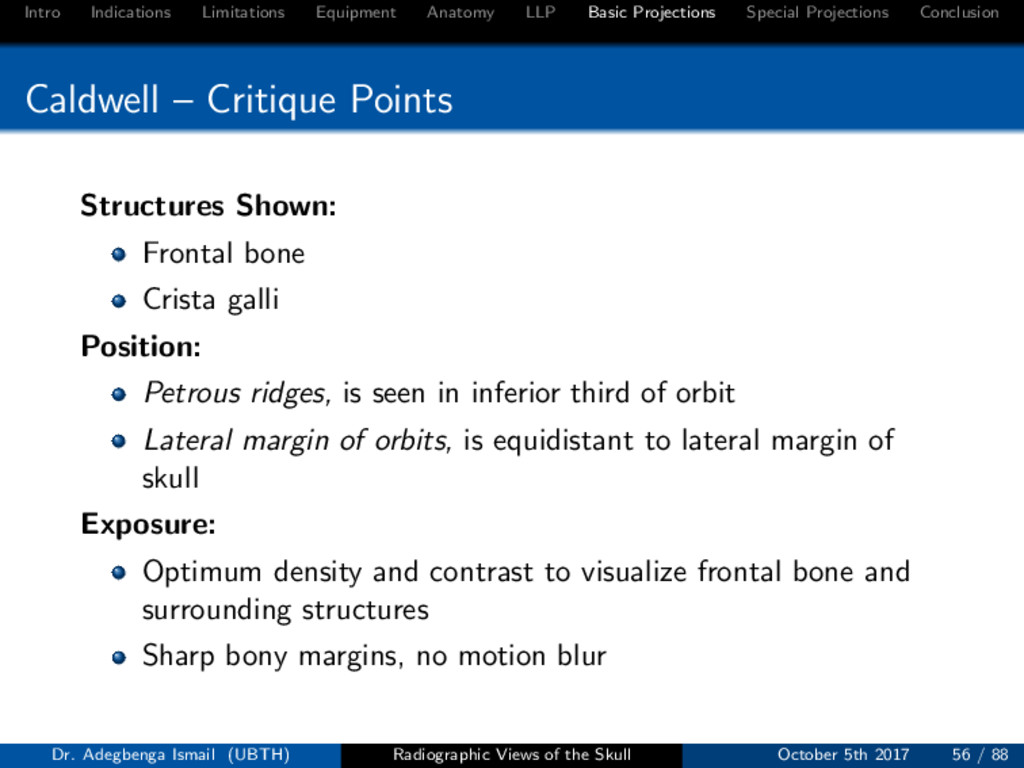
Conclusion Caldwell – Critique Points Structures Shown: Frontal bone Crista galli Position: Petrous ridges, is seen in inferior third of orbit Lateral margin of orbits, is equidistant to lateral margin of skull Exposure: Optimum density and contrast to visualize frontal bone and surrounding structures Sharp bony margins, no motion blur Dr. Adegbenga Ismail (UBTH) Radiographic Views of the Skull October 5th 2017 56 / 88
Conclusion Antero-posterior half-axial (Towne’s) The Towne’s view is an angled Fronto-Occipital radiograph of the skull. It allows better visualization of the posterior cranial fossa. Cassette: 10 × 12” Length-wise Grid Dr. Adegbenga Ismail (UBTH) Radiographic Views of the Skull October 5th 2017 58 / 88
Conclusion Antero-posterior half-axial (Towne’s) Position: Supine on trolley or X-ray table Occiput rests on table bucky or IR MSP and Orbito-meatal plane ⊥ to IR Center IR to projected CR Dr. Adegbenga Ismail (UBTH) Radiographic Views of the Skull October 5th 2017 58 / 88
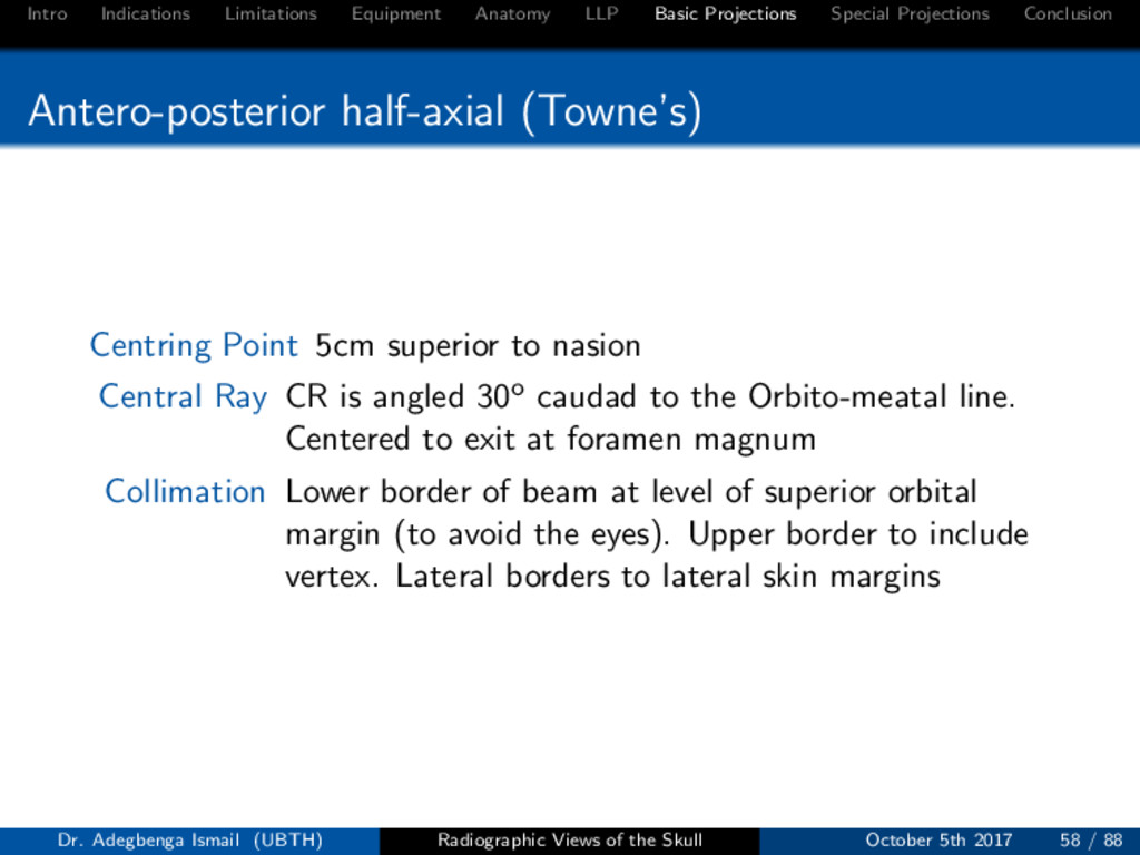
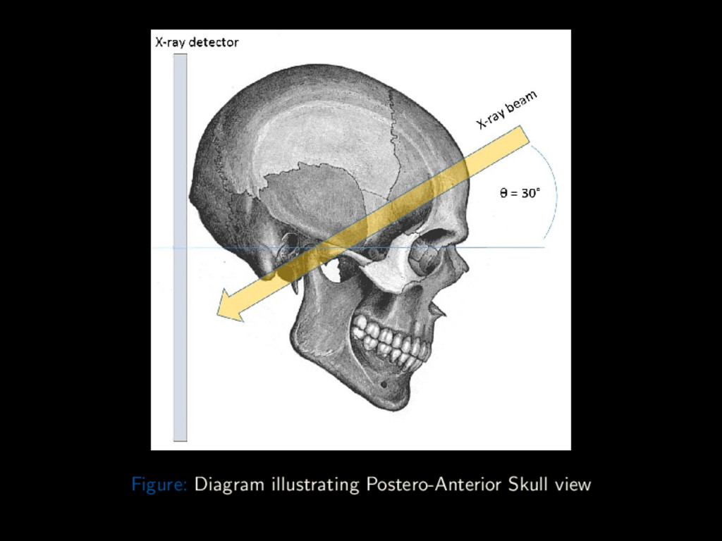
Conclusion Antero-posterior half-axial (Towne’s) Centring Point 5cm superior to nasion Central Ray CR is angled 30o caudad to the Orbito-meatal line. Centered to exit at foramen magnum Collimation Lower border of beam at level of superior orbital margin (to avoid the eyes). Upper border to include vertex. Lateral borders to lateral skin margins Dr. Adegbenga Ismail (UBTH) Radiographic Views of the Skull October 5th 2017 58 / 88
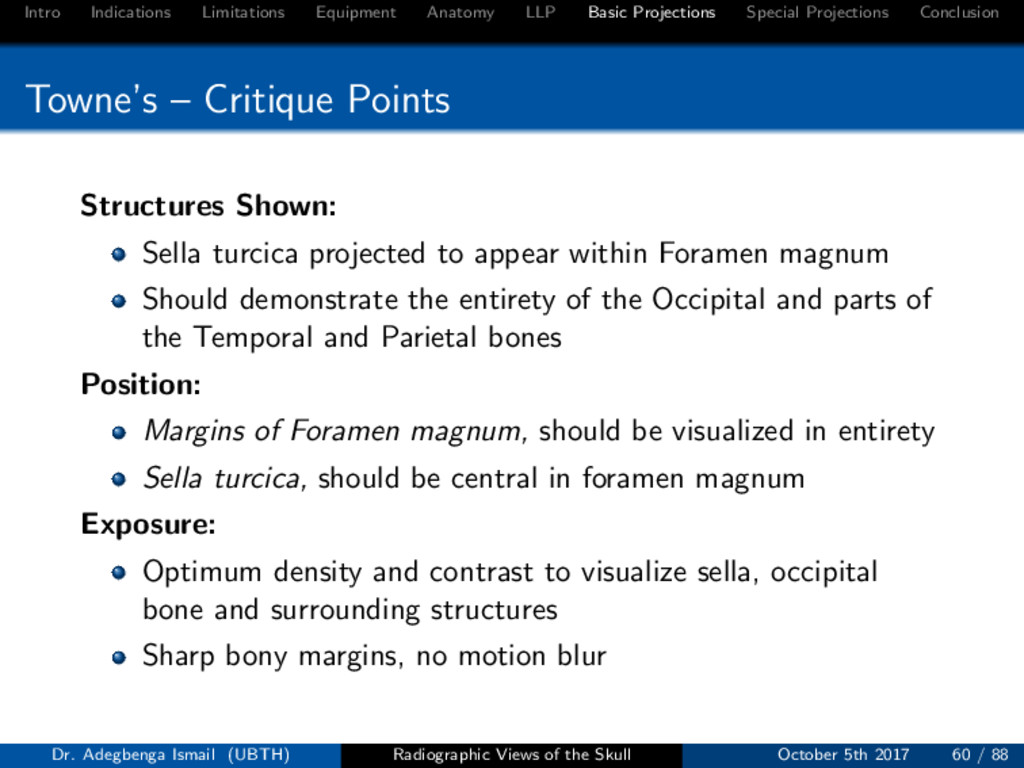
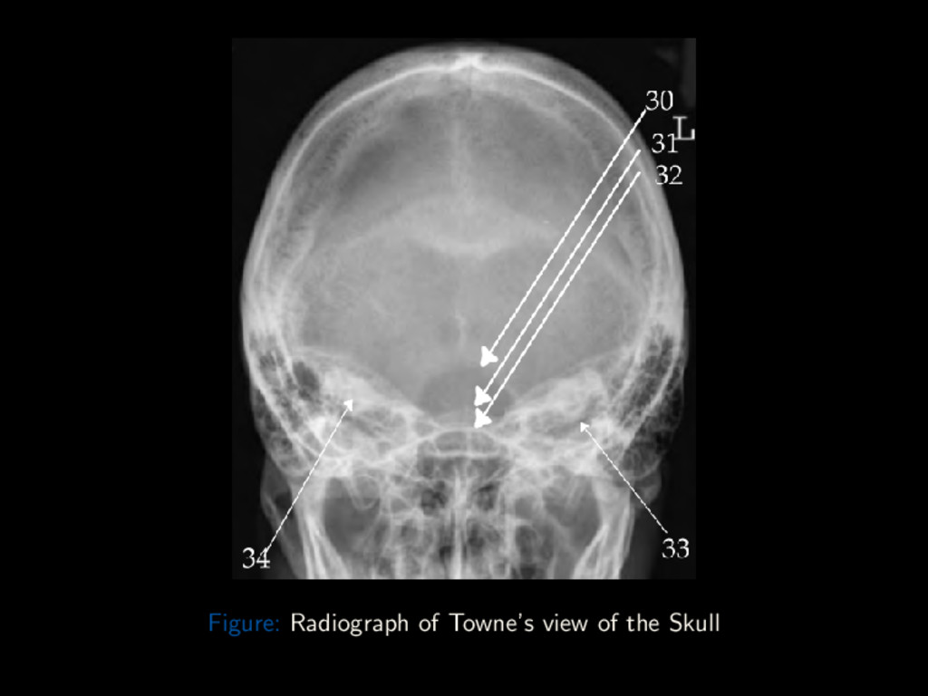
Conclusion Towne’s – Critique Points Structures Shown: Sella turcica projected to appear within Foramen magnum Should demonstrate the entirety of the Occipital and parts of the Temporal and Parietal bones Position: Margins of Foramen magnum, should be visualized in entirety Sella turcica, should be central in foramen magnum Exposure: Optimum density and contrast to visualize sella, occipital bone and surrounding structures Sharp bony margins, no motion blur Dr. Adegbenga Ismail (UBTH) Radiographic Views of the Skull October 5th 2017 60 / 88
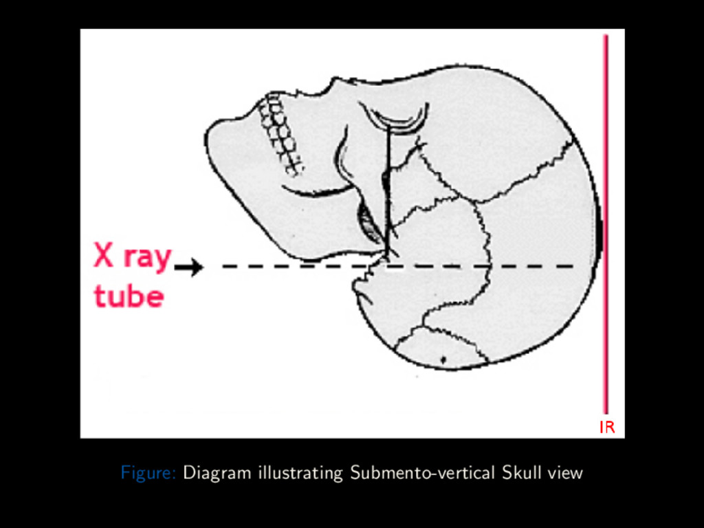
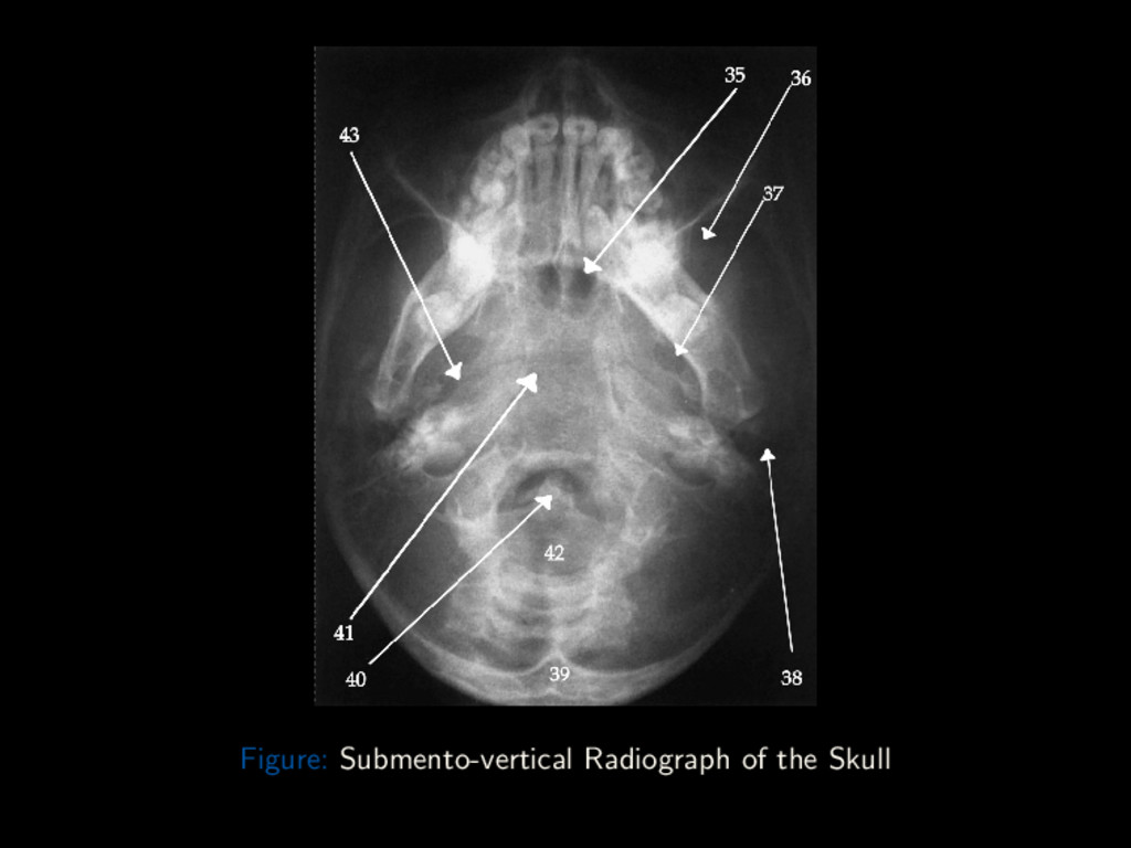
Conclusion Axial Basal (Submento-vertex) Projection The Submento-vertex view demonstrates advanced bony pathology of the base of the skull and the inner temporal bone. Warning: Rule out C-spine fracture or subluxation in trauma patients before attempting projection Cassette: 10 × 12” Length-wise Grid Dr. Adegbenga Ismail (UBTH) Radiographic Views of the Skull October 5th 2017 62 / 88
Conclusion Axial Basal (Submento-vertex) Projection Position: Seated erect or Supine with neck hyper-extended over edge of table resting vertex on IR IOML is to IR Center IR to projected CR Dr. Adegbenga Ismail (UBTH) Radiographic Views of the Skull October 5th 2017 62 / 88
Conclusion Axial Basal (Submento-vertex) Projection Centring Point Mid-point between the Gonions (Angles of Mandibles) Central Ray CR is ⊥ to IOML. Centered to 2cm anterior to level of EAMs Collimation On four sides to skull margins Dr. Adegbenga Ismail (UBTH) Radiographic Views of the Skull October 5th 2017 62 / 88
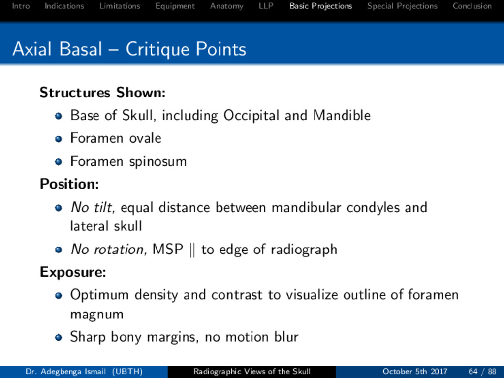
Conclusion Axial Basal – Critique Points Structures Shown: Base of Skull, including Occipital and Mandible Foramen ovale Foramen spinosum Position: No tilt, equal distance between mandibular condyles and lateral skull No rotation, MSP to edge of radiograph Exposure: Optimum density and contrast to visualize outline of foramen magnum Sharp bony margins, no motion blur Dr. Adegbenga Ismail (UBTH) Radiographic Views of the Skull October 5th 2017 64 / 88
Conclusion Paranasal Sinuses The paranasal sinuses are air-filled cavities within the bones of the skull. The paranasal sinuses comprises of: Frontal air cells Ethmoid air cells Sphenoid sinus Maxillary antrum Dr. Adegbenga Ismail (UBTH) Radiographic Views of the Skull October 5th 2017 66 / 88
Conclusion Paranasal Sinuses A detailed study of the paranasal sinuses should include three basic projections and an optional fourth. These projections are: Inclined PA (Caldwell) Occipito-mental (Water’s) Lateral Submento-vertex (Optional) Dr. Adegbenga Ismail (UBTH) Radiographic Views of the Skull October 5th 2017 67 / 88
Conclusion Paranasal Sinuses Inclined PA (Caldwell) and Submento-vertex Patient positioning, Central ray angulation and centring point is as earlier described in general skull survey. Lateral Centring Point Midway between EAM and Lateral canthus Otherwise similar to lateral in general skull projections. Dr. Adegbenga Ismail (UBTH) Radiographic Views of the Skull October 5th 2017 68 / 88
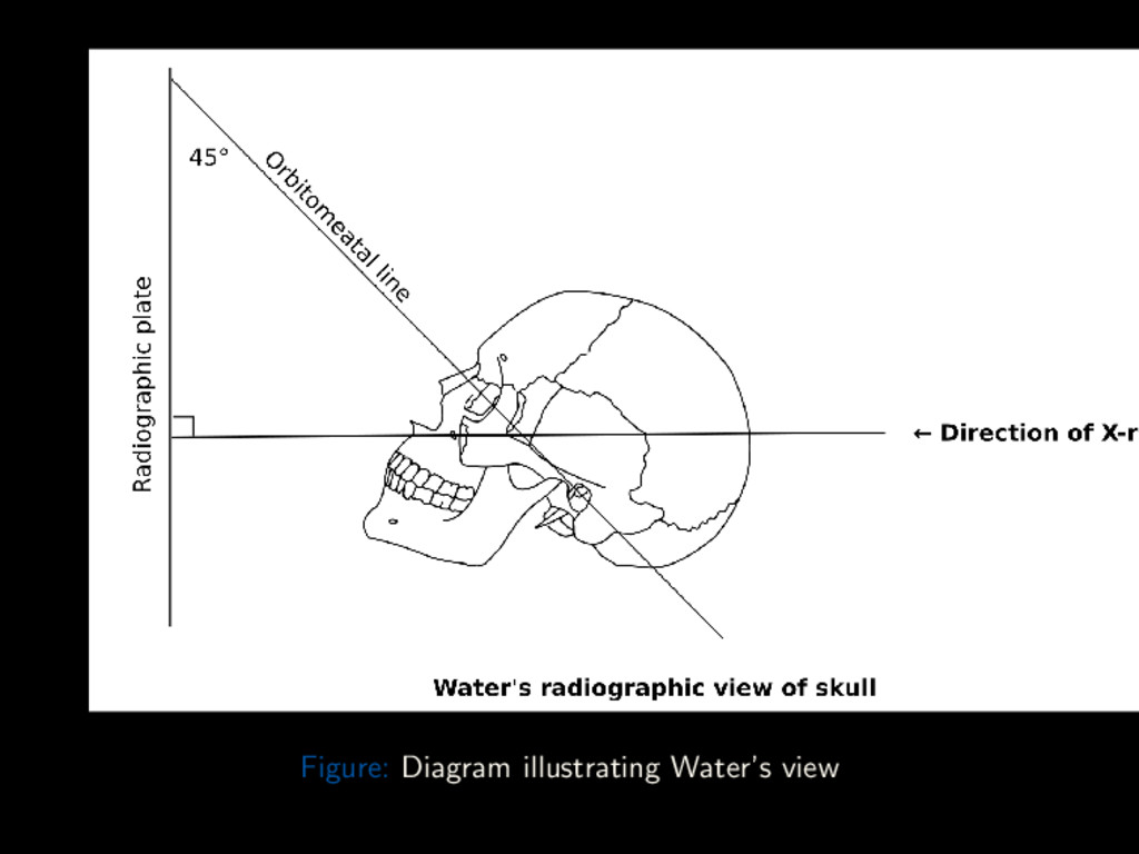
Conclusion Paranasal Sinuses Occipito-mental (Water’s) View Position: Seated erect, with chin extended and touching bucky Nose is 2 – 3cm away from bucky Adjust height of IR to center IR to acanthion MSP is ⊥ to IR OML is 45o to IR (Variation:) MML is ⊥ to IR Center IR to projected CR (Optional) Patient opens mouth to better visualize the sphenoid sinus Dr. Adegbenga Ismail (UBTH) Radiographic Views of the Skull October 5th 2017 69 / 88
Conclusion Paranasal Sinuses Occipito-mental (Water’s) View Centring Point 2 – 3cm superior to inion to exit at Acanthion Central Ray CR is ⊥ to IM. Collimation On four sides to skull margins Dr. Adegbenga Ismail (UBTH) Radiographic Views of the Skull October 5th 2017 69 / 88
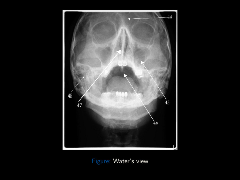
Conclusion Water’s view – Critique Points Structures Shown: Unobstructed view of the maxillary sinuses Position: Petrous ridges just inferior to floor of maxillary sinuses No rotation, equal distance between orbits and lateral skull Exposure: Optimum density and contrast to visualize paranasal sinuses Sharp bony margins, no motion blur Dr. Adegbenga Ismail (UBTH) Radiographic Views of the Skull October 5th 2017 71 / 88
Conclusion Sella turcica A detailed study of the sella should include the following projections: Lateral Antero-posterior half-axial Straight antero-posterior Submento-vertex (Axial) These projections are similar to those discussed in the general skull survey. Except collimate to around the sella turcica (2cm anterior, 2cm superior to EAM). Dr. Adegbenga Ismail (UBTH) Radiographic Views of the Skull October 5th 2017 73 / 88
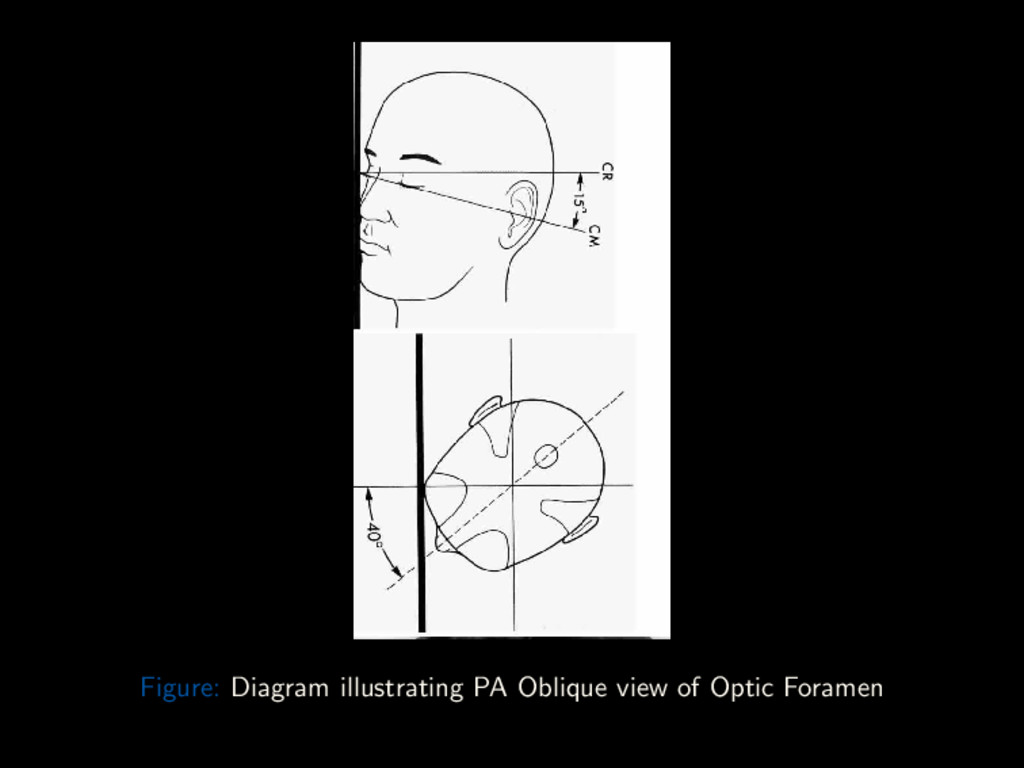
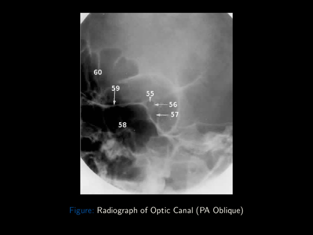
Conclusion Optic canal (PA Oblique) Cassette: 8 × 10” cross-wise Right and Left sides taken for comparison Position: Seated erect or prone on table Nose and chin touching image receptor OML is 15o to the CR Rotate the head so MSP subtends an angle of 50o to the film Central Ray directed ⊥ to IM Centring Point contra-lateral occiput, ray emerging through the orbit against the film Dr. Adegbenga Ismail (UBTH) Radiographic Views of the Skull October 5th 2017 75 / 88
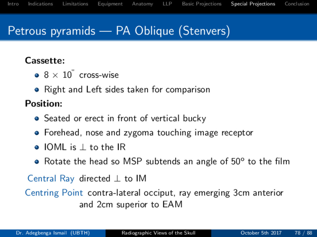
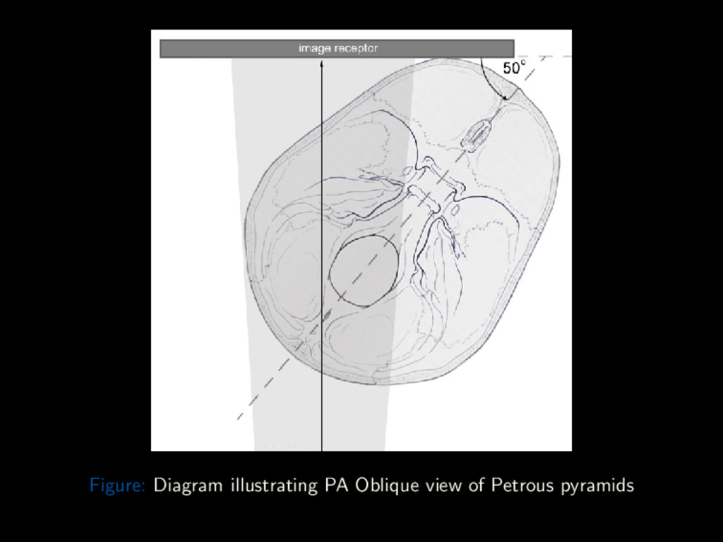
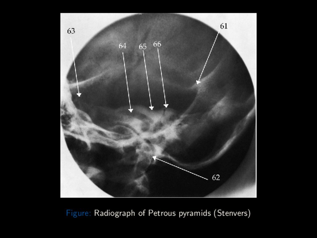
Conclusion Petrous pyramids — PA Oblique (Stenvers) Cassette: 8 × 10” cross-wise Right and Left sides taken for comparison Position: Seated or erect in front of vertical bucky Forehead, nose and zygoma touching image receptor IOML is ⊥ to the IR Rotate the head so MSP subtends an angle of 50o to the film Central Ray directed ⊥ to IM Centring Point contra-lateral occiput, ray emerging 3cm anterior and 2cm superior to EAM Dr. Adegbenga Ismail (UBTH) Radiographic Views of the Skull October 5th 2017 78 / 88
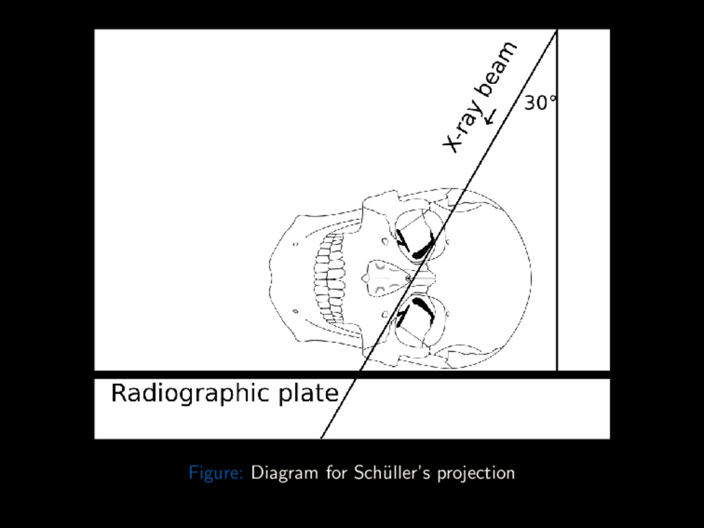
Conclusion Mastoids A detailed study of the mastoid should include the following projections: Lateral (Sch¨ uller’s) Antero-posterior half-axial Postero-anterior oblique (Stenvers) These projections, except the Sch¨ uller’s view, are similar to those discussed earlier. Sch¨ uller’s view is a lateral projection with a 30o caudal angulation of the CR. Centring Point is 3cm above and 1cm behind opposite EAM, to exit at EAM close to the IR. Dr. Adegbenga Ismail (UBTH) Radiographic Views of the Skull October 5th 2017 81 / 88
Conclusion Summary Landmarks, Points and Planes enable precise positioning of patients OML, IOML and MSP Used in a lot of projections Centring Point, Direction of CR follow the anatomical structure to image. All these facilitate obtaining good images without repeat exposures. Dr. Adegbenga Ismail (UBTH) Radiographic Views of the Skull October 5th 2017 84 / 88
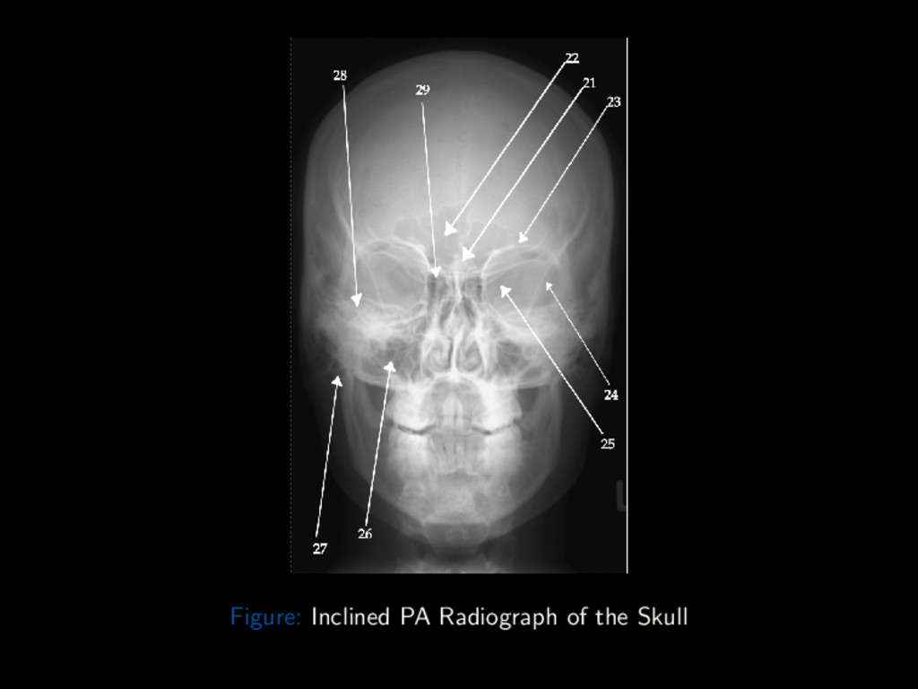
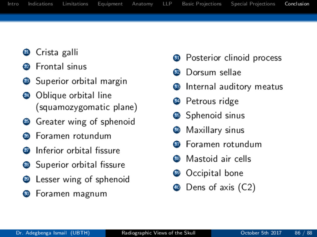
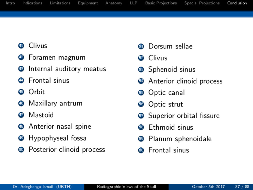
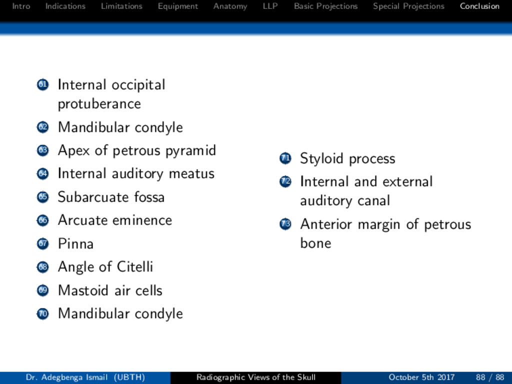
Conclusion 21 Crista galli 22 Frontal sinus 23 Superior orbital margin 24 Oblique orbital line (squamozygomatic plane) 25 Greater wing of sphenoid 26 Foramen rotundum 27 Inferior orbital fissure 28 Superior orbital fissure 29 Lesser wing of sphenoid 30 Foramen magnum 31 Posterior clinoid process 32 Dorsum sellae 33 Internal auditory meatus 34 Petrous ridge 35 Sphenoid sinus 36 Maxillary sinus 37 Foramen rotundum 38 Mastoid air cells 39 Occipital bone 40 Dens of axis (C2) Dr. Adegbenga Ismail (UBTH) Radiographic Views of the Skull October 5th 2017 86 / 88