Alert Height 2.4 Runway Visual Range 2.5 Fail-passive Autoland System 2.6 Fail-operational Autoland System 2.7 Minimum Approach Break-off Height 2.8 Concept of Minima Module 2 - General Concepts
pilot of an aircraft on the centerline of the runway can see the runway surface markings or the lights delineating the runway or identifying its centerline (ICAO). Runway Visual Range Definition
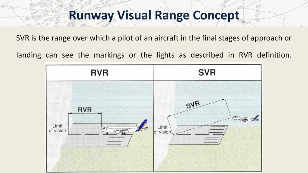
reports of the visibility conditions which a pilot may expect to encounter in the touchdown zone and along the runway. RVR measurements replace the use of Reported Visibility Values (RVV), which is not appropriate for conditions encountered during the final approach and landing in low visibility, because the visibility observations are often several miles away from the touchdown zone of the runway. Note: RVR is not the Slant Visual Range (SVR). Runway Visual Range Concept
are provided by a system of calibrated transmissometers and account for the effects of ambient background light and the intensity of runway lights (see Module 6 for further details). Transmissometer systems are strategically located to provide RVR measurements associated with three basic portions of a runway: Runway Visual Range Measurements
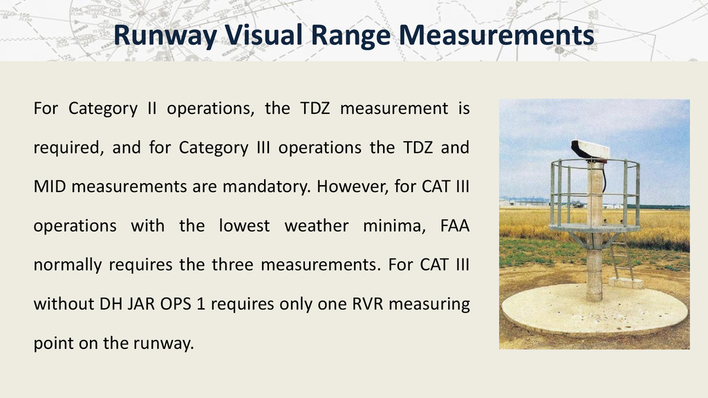
for Category III operations the TDZ and MID measurements are mandatory. However, for CAT III operations with the lowest weather minima, FAA normally requires the three measurements. For CAT III without DH JAR OPS 1 requires only one RVR measuring point on the runway. Runway Visual Range Measurements
expressed in terms of DH and RVR. It is relatively simple to establish the DH. However, it is more difficult to establish the RVR to be associated with that DH in order to ensure the required visual reference (three-light segment). When establishing airfield operating minima, it is recommended to refer to acceptable minima as described in Module 3 paragraph 2. The use of those minima has resulted in a high approach success rate. Establishment of RVR Minima
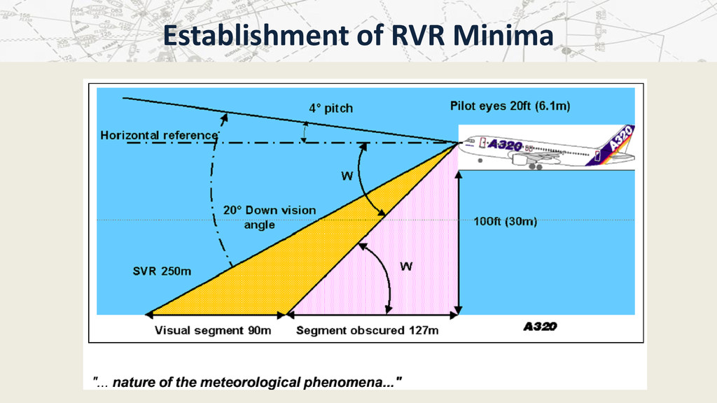
document n°17) The basic principles for the establishment of RVR minima are that the scale of visual reference required by a pilot at and below DH depends on the task that he has to carry out and that the degree to which his vision is obscured depends on the nature of the meteorological phenomena, which creates the low visibility conditions. “… the task that he has to carry out ...” Establishment of RVR Minima
1. most pilots require visual contact to be established about three seconds above DH though it has been observed that this reduces to about one second when a fail-operational automatic landing system is being used; 2. to establish lateral position and cross-track velocity, most pilots require to be able to see not less than a three-light segment of the centerline of the approach lights, or runway centerline, or runway edge lights; Establishment of RVR Minima
be able to see a lateral element of the ground pattern, i.e. an approach lighting cross-bar, the landing threshold, or a barrette of the touchdown zone lighting; 4. to make an accurate adjustment to the flight path in the vertical plane, such as a flare, using purely visual cues, most pilots require to be able to see a point on the ground that has a low or zero rate of apparent movement relative to the aircraft. Establishment of RVR Minima
category. Typical values are 60m for CAT III and 90m for CAT II automatic landing and 225m for CAT II with manual landing. Note 1: the visual segment is the runway segment that a pilot can see from his position. Establishment of RVR Minima
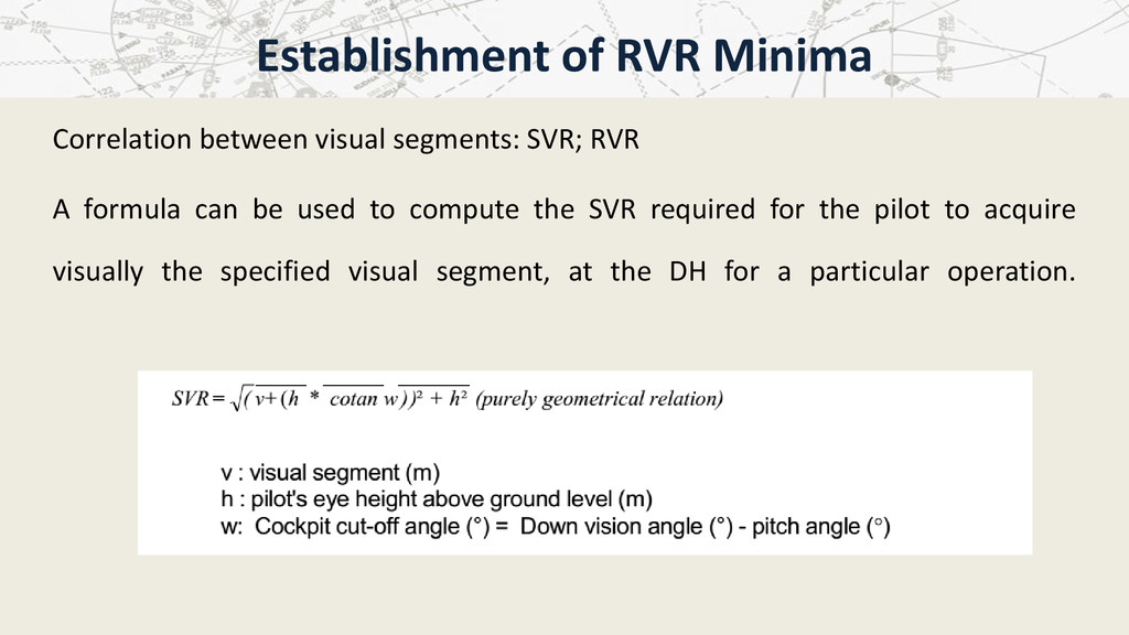
used to compute the SVR required for the pilot to acquire visually the specified visual segment, at the DH for a particular operation. Establishment of RVR Minima
Kingdom over a twenty year period have shown that in deep stable fog there is a 90% probability that the SVR from eye heights greater than 15ft above the ground will be less than the RVR. There is some evidence in pilots' reports that other low visibility conditions (heavy rain, blowing snow, dust, etc.) could produce a relationship similar to that observed in fog. Establishment of RVR Minima
established in the UK for deep stable fog can be used. Refer to the following graph providing SVR/RVR ratio as a function of eye height. On 90% of occasions, the SVR is expected to be this proportion of RVR or more. Establishment of RVR Minima
manual control below, the required visual segment is 90m. The required SVR for such operation is 220.7m (using the example as shown in Figure 2.4). Eye height = DH + 20ft =120ft = 36.6m Cutoff angle = 20° Example of Establishment of Required RVR
we find SVR =220.7 m At 120ft above ground level, the SVR/RVR is expected to be 0.68 or more, so we obtain a required RVR equal 324.6m. RVR = SVR x 1/0.68 = 324.6 m (for SVR/RVR=0.68) The same method may also be used to evaluate the visual segment for a given RVR. Example of Establishment of Required RVR
the past. But with recent experience, it has been found that with the improvement in the performance of visual aids, and the increased use of automatic equipment in the new larger aircraft, most of the variables cancel each other out and a simple tabulation can be constructed which is applicable to a wide range of aircraft. Example of Establishment of Required RVR
low visibility approaches and landing. A too-low seat adjustment may greatly reduce the visual segment. When the eye reference position is lower than intended, the already short visual segment is further reduced by the cut-off angle of the glareshield or nose. Additional Information on Pilot´s Eye Position
The optimum eye position is obtained when the pilot sees the red indicator ball covering the white ball. Additional Information on Pilot´s Eye Position
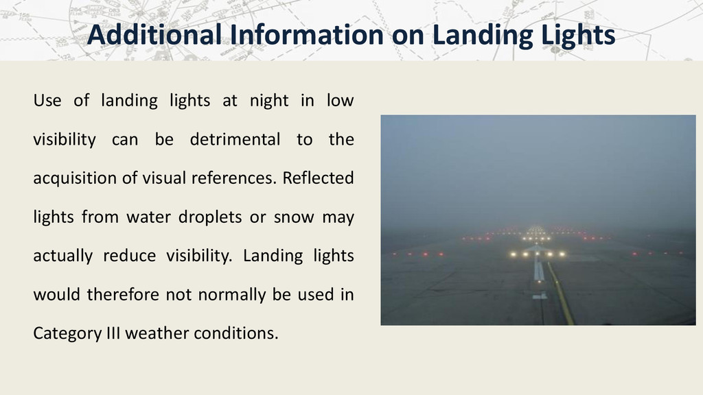
be detrimental to the acquisition of visual references. Reflected lights from water droplets or snow may actually reduce visibility. Landing lights would therefore not normally be used in Category III weather conditions. Additional Information on Landing Lights