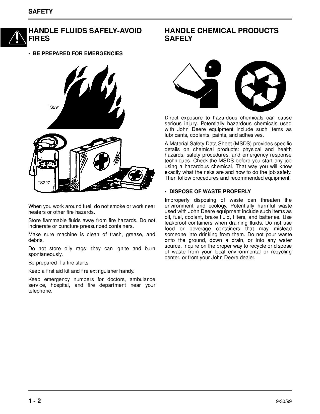
BE PREPARED FOR EMERGENCIES When you work around fuel, do not smoke or work near heaters or other fire hazards. Store flammable fluids away from fire hazards. Do not incinerate or puncture pressurized containers. Make sure machine is clean of trash, grease, and debris. Do not store oily rags; they can ignite and burn spontaneously. Be prepared if a fire starts. Keep a first aid kit and fire extinguisher handy. Keep emergency numbers for doctors, ambulance service, hospital, and fire department near your telephone. HANDLE CHEMICAL PRODUCTS SAFELY Direct exposure to hazardous chemicals can cause serious injury. Potentially hazardous chemicals used with John Deere equipment include such items as lubricants, coolants, paints, and adhesives. A Material Safety Data Sheet (MSDS) provides specific details on chemical products: physical and health hazards, safety procedures, and emergency response techniques. Check the MSDS before you start any job using a hazardous chemical. That way you will know exactly what the risks are and how to do the job safely. Then follow procedures and recommended equipment. • DISPOSE OF WASTE PROPERLY Improperly disposing of waste can threaten the environment and ecology. Potentially harmful waste used with John Deere equipment include such items as oil, fuel, coolant, brake fluid, filters, and batteries. Use leakproof containers when draining fluids. Do not use food or beverage containers that may mislead someone into drinking from them. Do not pour waste onto the ground, down a drain, or into any water source. Inquire on the proper way to recycle or dispose of waste from your local environmental or recycling center, or from your John Deere dealer. TS227 TS291
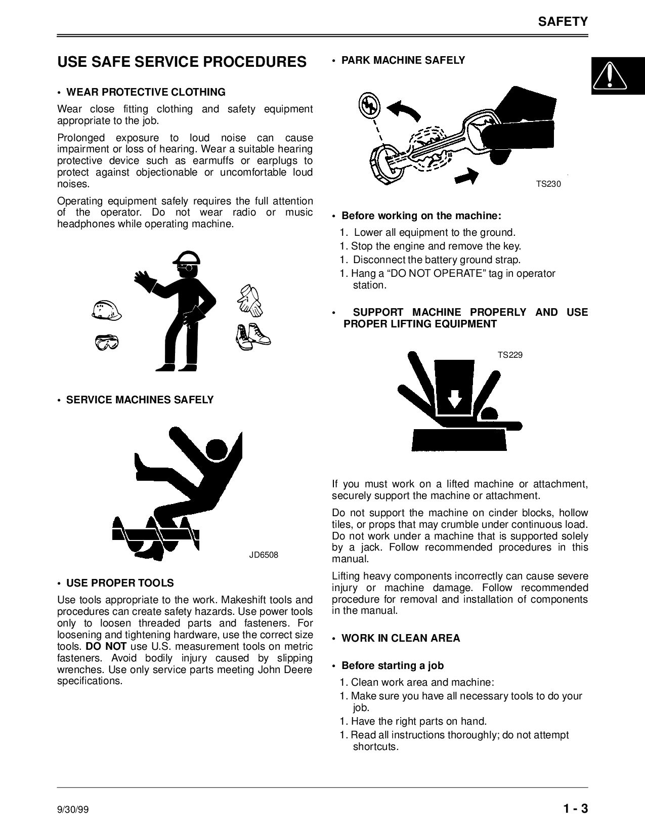
WEAR PROTECTIVE CLOTHING Wear close fitting clothing and safety equipment appropriate to the job. Prolonged exposure to loud noise can cause impairment or loss of hearing. Wear a suitable hearing protective device such as earmuffs or earplugs to protect against objectionable or uncomfortable loud noises. Operating equipment safely requires the full attention of the operator. Do not wear radio or music headphones while operating machine. • SERVICE MACHINES SAFELY • USE PROPER TOOLS Use tools appropriate to the work. Makeshift tools and procedures can create safety hazards. Use power tools only to loosen threaded parts and fasteners. For loosening and tightening hardware, use the correct size tools. DO NOT use U.S. measurement tools on metric fasteners. Avoid bodily injury caused by slipping wrenches. Use only service parts meeting John Deere specifications. • PARK MACHINE SAFELY • Before working on the machine: 1. Lower all equipment to the ground. 1. Stop the engine and remove the key. 1. Disconnect the battery ground strap. 1. Hang a “DO NOT OPERATE” tag in operator station. • SUPPORT MACHINE PROPERLY AND USE PROPER LIFTING EQUIPMENT If you must work on a lifted machine or attachment, securely support the machine or attachment. Do not support the machine on cinder blocks, hollow tiles, or props that may crumble under continuous load. Do not work under a machine that is supported solely by a jack. Follow recommended procedures in this manual. Lifting heavy components incorrectly can cause severe injury or machine damage. Follow recommended procedure for removal and installation of components in the manual. • WORK IN CLEAN AREA • Before starting a job 1. Clean work area and machine: 1. Make sure you have all necessary tools to do your job. 1. Have the right parts on hand. 1. Read all instructions thoroughly; do not attempt shortcuts. JD6508 TS230 TS229
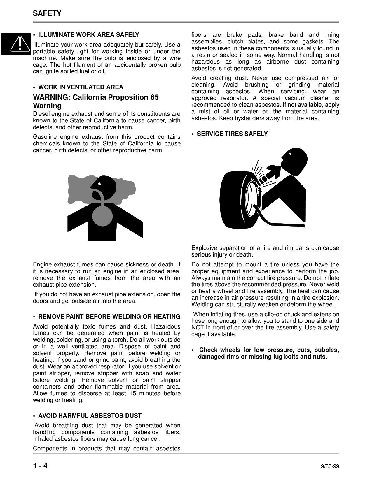
Illuminate your work area adequately but safely. Use a portable safety light for working inside or under the machine. Make sure the bulb is enclosed by a wire cage. The hot filament of an accidentally broken bulb can ignite spilled fuel or oil. • WORK IN VENTILATED AREA WARNING: California Proposition 65 Warning Diesel engine exhaust and some of its constituents are known to the State of California to cause cancer, birth defects, and other reproductive harm. Gasoline engine exhaust from this product contains chemicals known to the State of California to cause cancer, birth defects, or other reproductive harm. Engine exhaust fumes can cause sickness or death. If it is necessary to run an engine in an enclosed area, remove the exhaust fumes from the area with an exhaust pipe extension. If you do not have an exhaust pipe extension, open the doors and get outside air into the area. • REMOVE PAINT BEFORE WELDING OR HEATING Avoid potentially toxic fumes and dust. Hazardous fumes can be generated when paint is heated by welding, soldering, or using a torch. Do all work outside or in a well ventilated area. Dispose of paint and solvent properly. Remove paint before welding or heating: If you sand or grind paint, avoid breathing the dust. Wear an approved respirator. If you use solvent or paint stripper, remove stripper with soap and water before welding. Remove solvent or paint stripper containers and other flammable material from area. Allow fumes to disperse at least 15 minutes before welding or heating. • AVOID HARMFUL ASBESTOS DUST :Avoid breathing dust that may be generated when handling components containing asbestos fibers. Inhaled asbestos fibers may cause lung cancer. Components in products that may contain asbestos fibers are brake pads, brake band and lining assemblies, clutch plates, and some gaskets. The asbestos used in these components is usually found in a resin or sealed in some way. Normal handling is not hazardous as long as airborne dust containing asbestos is not generated. Avoid creating dust. Never use compressed air for cleaning. Avoid brushing or grinding material containing asbestos. When servicing, wear an approved respirator. A special vacuum cleaner is recommended to clean asbestos. If not available, apply a mist of oil or water on the material containing asbestos. Keep bystanders away from the area. • SERVICE TIRES SAFELY Explosive separation of a tire and rim parts can cause serious injury or death. Do not attempt to mount a tire unless you have the proper equipment and experience to perform the job. Always maintain the correct tire pressure. Do not inflate the tires above the recommended pressure. Never weld or heat a wheel and tire assembly. The heat can cause an increase in air pressure resulting in a tire explosion. Welding can structurally weaken or deform the wheel. When inflating tires, use a clip-on chuck and extension hose long enough to allow you to stand to one side and NOT in front of or over the tire assembly. Use a safety cage if available. • Check wheels for low pressure, cuts, bubbles, damaged rims or missing lug bolts and nuts.
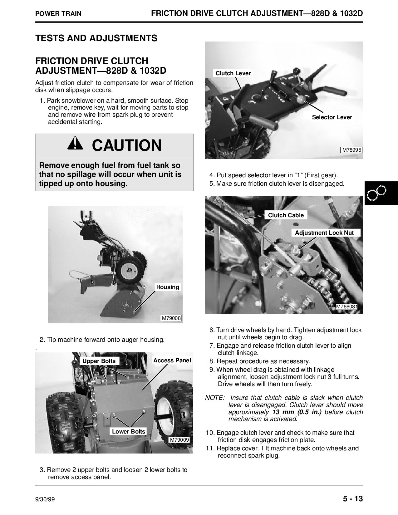
& 1032D TESTS AND ADJUSTMENTS FRICTION DRIVE CLUTCH ADJUSTMENT—828D & 1032D Adjust friction clutch to compensate for wear of friction disk when slippage occurs. 1. Park snowblower on a hard, smooth surface. Stop engine, remove key, wait for moving parts to stop and remove wire from spark plug to prevent accidental starting. 2. Tip machine forward onto auger housing. . 3. Remove 2 upper bolts and loosen 2 lower bolts to remove access panel. 4. Put speed selector lever in “1” (First gear). 5. Make sure friction clutch lever is disengaged. 6. Turn drive wheels by hand. Tighten adjustment lock nut until wheels begin to drag. 7. Engage and release friction clutch lever to align clutch linkage. 8. Repeat procedure as necessary. 9. When wheel drag is obtained with linkage alignment, loosen adjustment lock nut 3 full turns. Drive wheels will then turn freely. NOTE: Insure that clutch cable is slack when clutch lever is disengaged. Clutch lever should move approximately 13 mm (0.5 in.) before clutch mechanism is activated. 10. Engage clutch lever and check to make sure that friction disk engages friction plate. 11. Replace cover. Tilt machine back onto wheels and reconnect spark plug. c CAUTION Remove enough fuel from fuel tank so that no spillage will occur when unit is tipped up onto housing. M79008 Housing M79009 Lower Bolts Upper Bolts Access Panel M78995 Selector Lever Clutch Lever M766081 Adjustment Lock Nut Clutch Cable
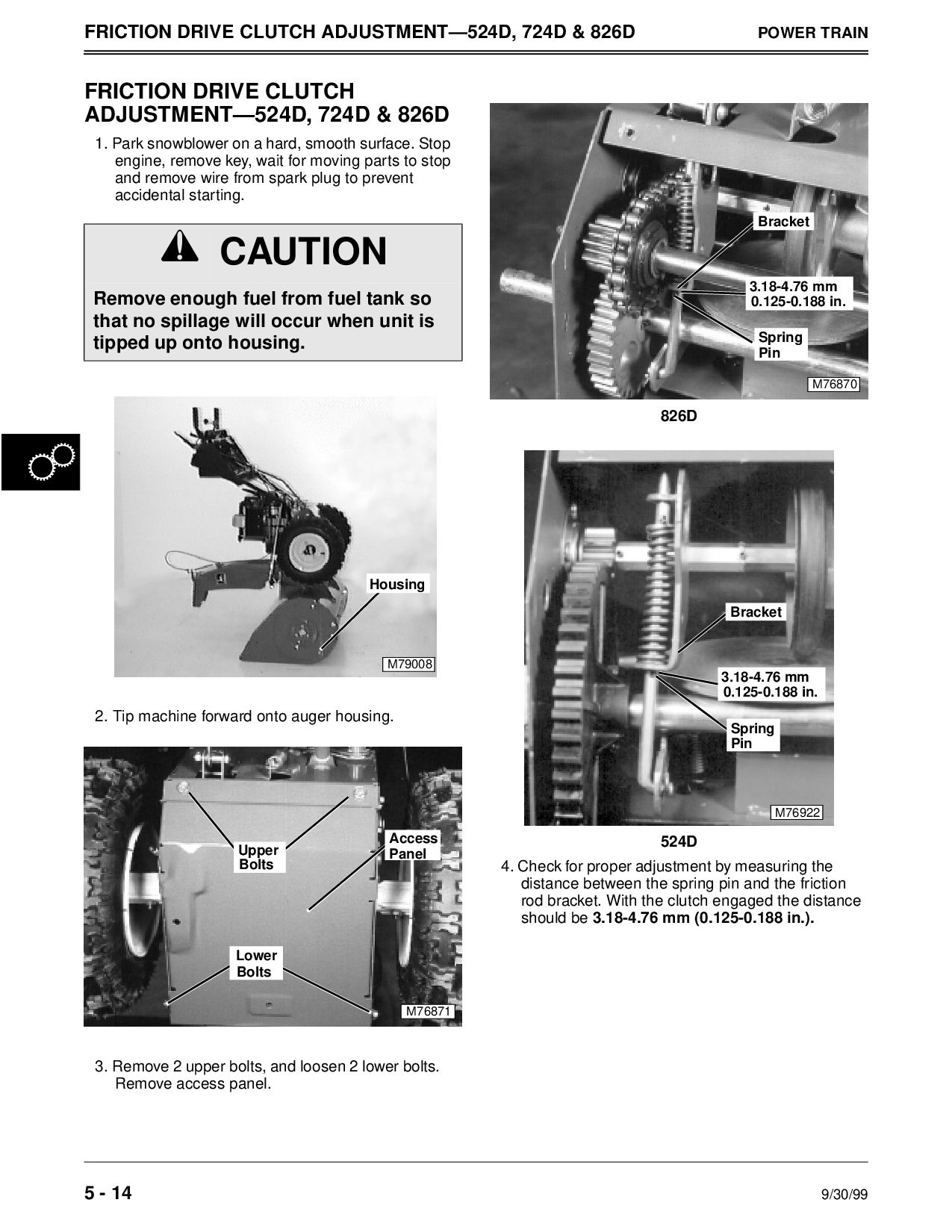
826D POWER TRAIN FRICTION DRIVE CLUTCH ADJUSTMENT—524D, 724D & 826D 1. Park snowblower on a hard, smooth surface. Stop engine, remove key, wait for moving parts to stop and remove wire from spark plug to prevent accidental starting. 2. Tip machine forward onto auger housing. 3. Remove 2 upper bolts, and loosen 2 lower bolts. Remove access panel. 826D 524D 4. Check for proper adjustment by measuring the distance between the spring pin and the friction rod bracket. With the clutch engaged the distance should be 3.18-4.76 mm (0.125-0.188 in.). c CAUTION Remove enough fuel from fuel tank so that no spillage will occur when unit is tipped up onto housing. M79008 Housing M76871 Upper Bolts Access Panel Lower Bolts M76870 Bracket 0.125-0.188 in. 3.18-4.76 mm Spring Pin Bracket 0.125-0.188 in. 3.18-4.76 mm Spring Pin M76922
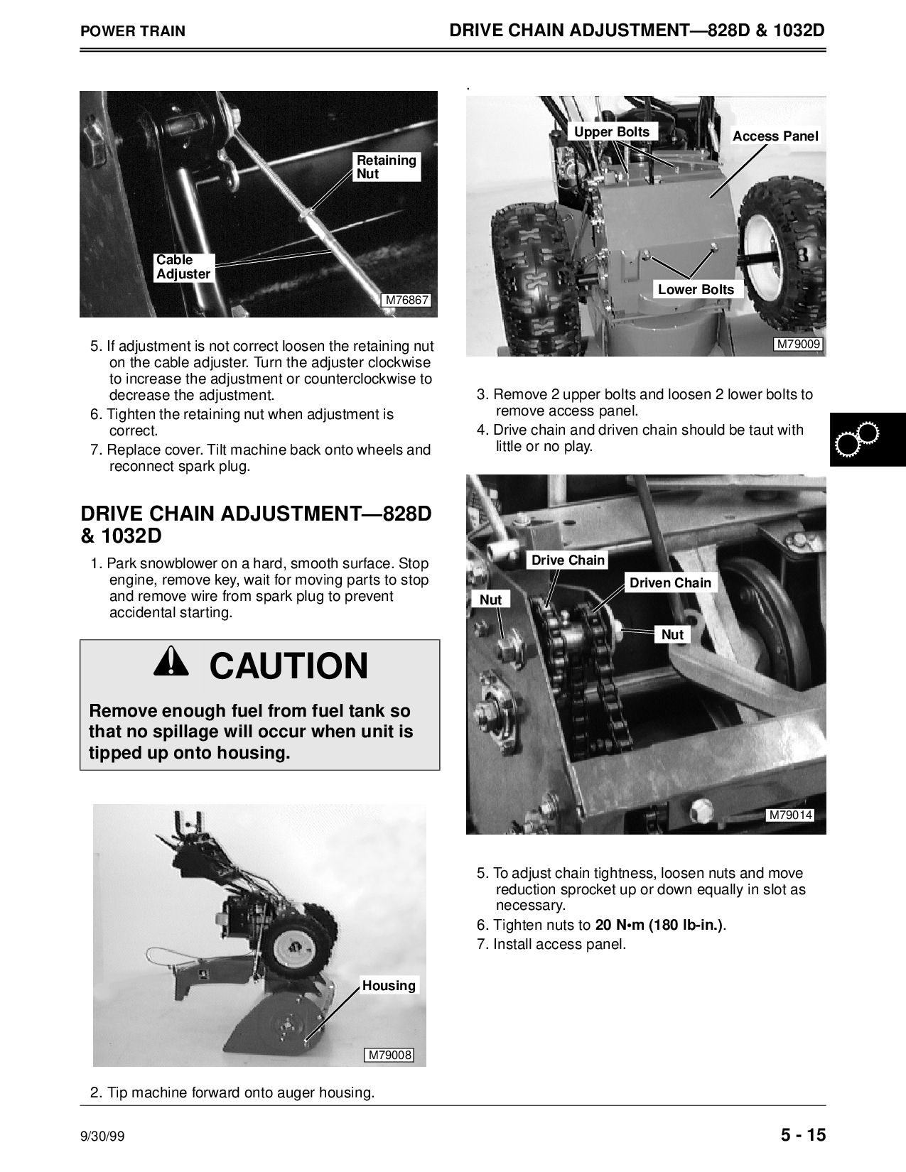
1032D 5. If adjustment is not correct loosen the retaining nut on the cable adjuster. Turn the adjuster clockwise to increase the adjustment or counterclockwise to decrease the adjustment. 6. Tighten the retaining nut when adjustment is correct. 7. Replace cover. Tilt machine back onto wheels and reconnect spark plug. DRIVE CHAIN ADJUSTMENT—828D & 1032D 1. Park snowblower on a hard, smooth surface. Stop engine, remove key, wait for moving parts to stop and remove wire from spark plug to prevent accidental starting. 2. Tip machine forward onto auger housing. c CAUTION Remove enough fuel from fuel tank so that no spillage will occur when unit is tipped up onto housing. M76867 Retaining Nut Cable Adjuster M79008 Housing . 3. Remove 2 upper bolts and loosen 2 lower bolts to remove access panel. 4. Drive chain and driven chain should be taut with little or no play. 5. To adjust chain tightness, loosen nuts and move reduction sprocket up or down equally in slot as necessary. 6. Tighten nuts to 20 N•m (180 lb-in.). 7. Install access panel. M79009 Upper Bolts Lower Bolts Access Panel M79014 Driven Chain Drive Chain Nut Nut
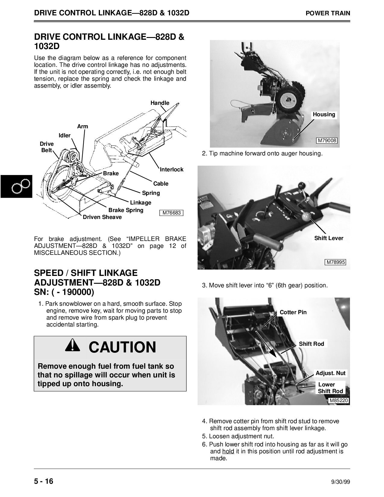
TRAIN DRIVE CONTROL LINKAGE—828D & 1032D Use the diagram below as a reference for component location. The drive control linkage has no adjustments. If the unit is not operating correctly, i.e. not enough belt tension, replace the spring and check the linkage and assembly, or idler assembly. For brake adjustment. (See “IMPELLER BRAKE ADJUSTMENT—828D & 1032D” on page 12 of MISCELLANEOUS SECTION.) SPEED / SHIFT LINKAGE ADJUSTMENT—828D & 1032D SN: ( - 190000) 1. Park snowblower on a hard, smooth surface. Stop engine, remove key, wait for moving parts to stop and remove wire from spark plug to prevent accidental starting. 2. Tip machine forward onto auger housing. 3. Move shift lever into “6” (6th gear) position. 4. Remove cotter pin from shift rod stud to remove shift rod assembly from shift lever linkage. 5. Loosen adjustment nut. 6. Push lower shift rod into housing as far as it will go and hold it in this position until rod adjustment is made. c CAUTION Remove enough fuel from fuel tank so that no spillage will occur when unit is tipped up onto housing. M76683 Handle Cable Spring Linkage Arm Idler Brake Brake Spring Drive Driven Sheave Interlock Belt M79008 Housing M78995 Shift Lever M85220 Adjust. Nut Cotter Pin Shift Rod Lower Shift Rod
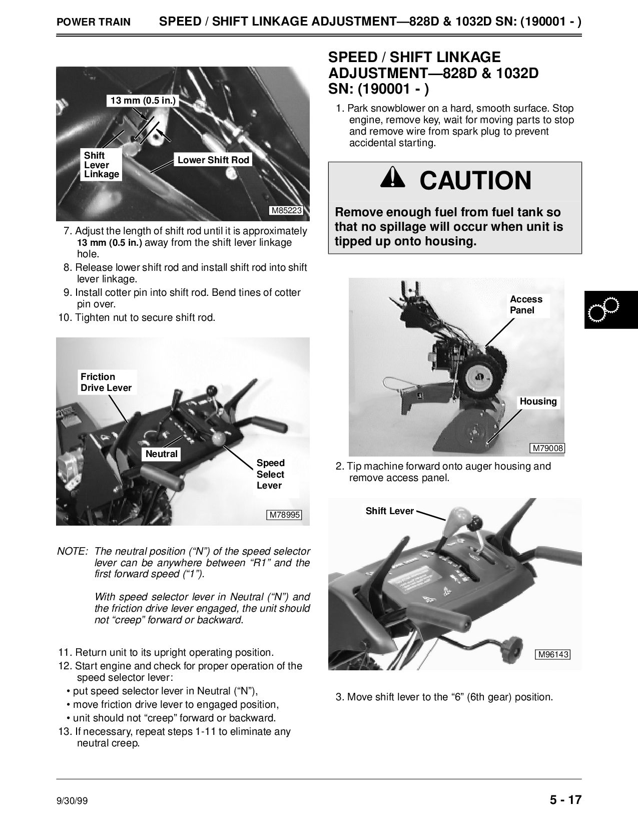
ADJUSTMENT—828D & 1032D SN: (190001 - ) 7. Adjust the length of shift rod until it is approximately 13 mm (0.5 in.) away from the shift lever linkage hole. 8. Release lower shift rod and install shift rod into shift lever linkage. 9. Install cotter pin into shift rod. Bend tines of cotter pin over. 10. Tighten nut to secure shift rod. NOTE: The neutral position (“N”) of the speed selector lever can be anywhere between “R1” and the first forward speed (“1”). With speed selector lever in Neutral (“N”) and the friction drive lever engaged, the unit should not “creep” forward or backward. 11. Return unit to its upright operating position. 12. Start engine and check for proper operation of the speed selector lever: • put speed selector lever in Neutral (“N”), • move friction drive lever to engaged position, • unit should not “creep” forward or backward. 13. If necessary, repeat steps 1-11 to eliminate any neutral creep. M85223 Shift Lever Linkage Lower Shift Rod 13 mm (0.5 in.) M78995 Friction Neutral Speed Select Lever Drive Lever SPEED / SHIFT LINKAGE ADJUSTMENT—828D & 1032D SN: (190001 - ) 1. Park snowblower on a hard, smooth surface. Stop engine, remove key, wait for moving parts to stop and remove wire from spark plug to prevent accidental starting. 2. Tip machine forward onto auger housing and remove access panel. 3. Move shift lever to the “6” (6th gear) position. c CAUTION Remove enough fuel from fuel tank so that no spillage will occur when unit is tipped up onto housing. M79008 Housing Access Panel M96143 Shift Lever
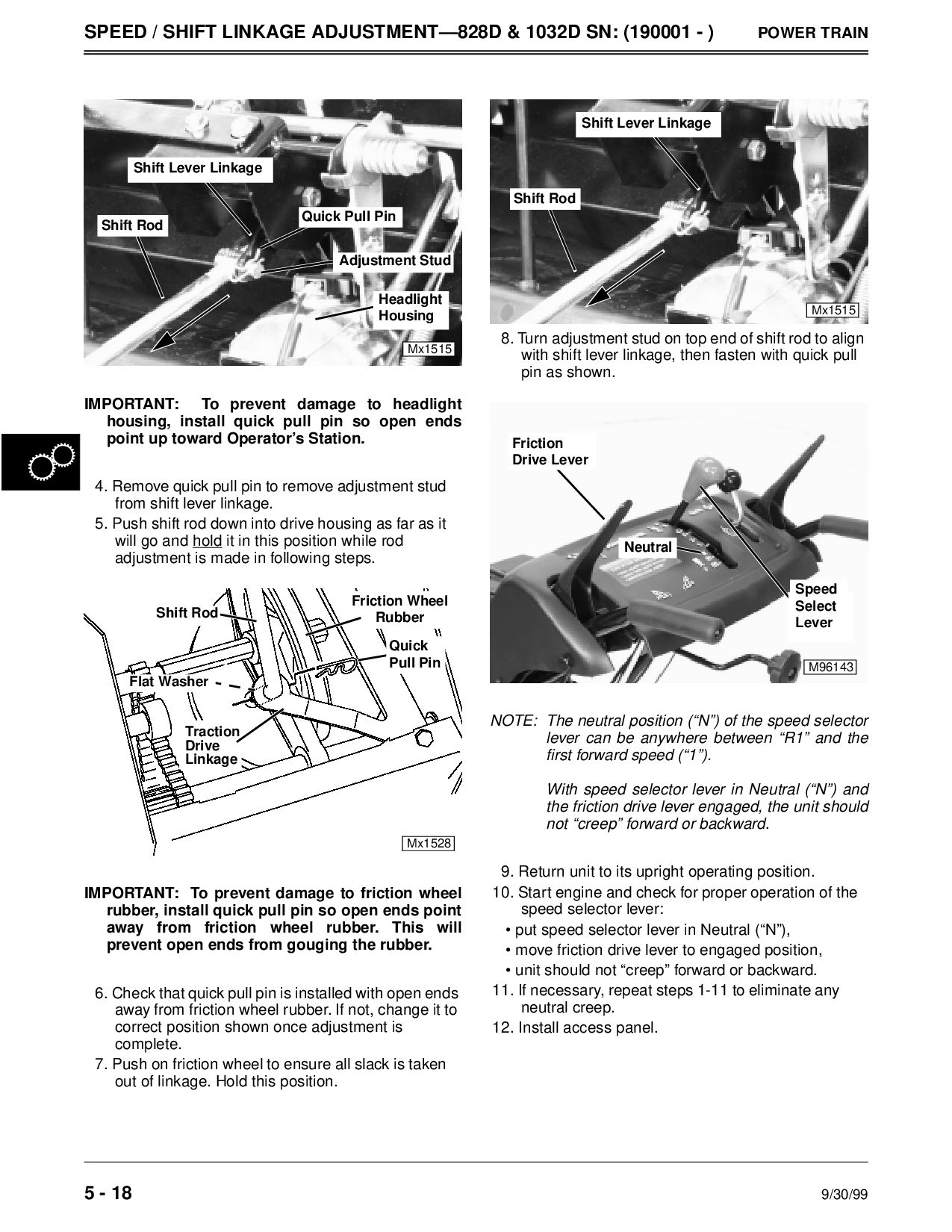
1032D SN: (190001 - ) POWER TRAIN IMPORTANT: To prevent damage to headlight housing, install quick pull pin so open ends point up toward Operator’s Station. 4. Remove quick pull pin to remove adjustment stud from shift lever linkage. 5. Push shift rod down into drive housing as far as it will go and hold it in this position while rod adjustment is made in following steps. IMPORTANT: To prevent damage to friction wheel rubber, install quick pull pin so open ends point away from friction wheel rubber. This will prevent open ends from gouging the rubber. 6. Check that quick pull pin is installed with open ends away from friction wheel rubber. If not, change it to correct position shown once adjustment is complete. 7. Push on friction wheel to ensure all slack is taken out of linkage. Hold this position. 8. Turn adjustment stud on top end of shift rod to align with shift lever linkage, then fasten with quick pull pin as shown. NOTE: The neutral position (“N”) of the speed selector lever can be anywhere between “R1” and the first forward speed (“1”). With speed selector lever in Neutral (“N”) and the friction drive lever engaged, the unit should not “creep” forward or backward. 9. Return unit to its upright operating position. 10. Start engine and check for proper operation of the speed selector lever: • put speed selector lever in Neutral (“N”), • move friction drive lever to engaged position, • unit should not “creep” forward or backward. 11. If necessary, repeat steps 1-11 to eliminate any neutral creep. 12. Install access panel. Mx1515 Shift Rod Adjustment Stud Shift Lever Linkage Quick Pull Pin Headlight Housing Mx1528 Traction Drive Linkage Shift Rod Quick Friction Wheel Rubber Pull Pin Flat Washer Mx1515 Shift Rod Shift Lever Linkage M96143 Neutral Speed Select Lever Friction Drive Lever
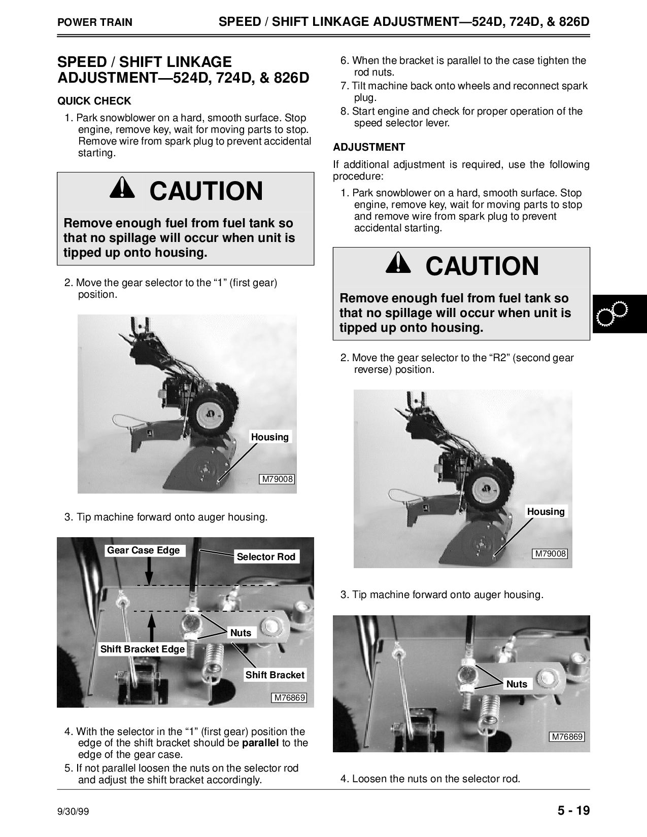
ADJUSTMENT—524D, 724D, & 826D SPEED / SHIFT LINKAGE ADJUSTMENT—524D, 724D, & 826D QUICK CHECK 1. Park snowblower on a hard, smooth surface. Stop engine, remove key, wait for moving parts to stop. Remove wire from spark plug to prevent accidental starting. 2. Move the gear selector to the “1” (first gear) position. 3. Tip machine forward onto auger housing. 4. With the selector in the “1” (first gear) position the edge of the shift bracket should be parallel to the edge of the gear case. 5. If not parallel loosen the nuts on the selector rod and adjust the shift bracket accordingly. 6. When the bracket is parallel to the case tighten the rod nuts. 7. Tilt machine back onto wheels and reconnect spark plug. 8. Start engine and check for proper operation of the speed selector lever. ADJUSTMENT If additional adjustment is required, use the following procedure: 1. Park snowblower on a hard, smooth surface. Stop engine, remove key, wait for moving parts to stop and remove wire from spark plug to prevent accidental starting. 2. Move the gear selector to the “R2” (second gear reverse) position. 3. Tip machine forward onto auger housing. 4. Loosen the nuts on the selector rod. c CAUTION Remove enough fuel from fuel tank so that no spillage will occur when unit is tipped up onto housing. M79008 Housing M76869 Shift Bracket Edge Gear Case Edge Selector Rod Nuts Shift Bracket c CAUTION Remove enough fuel from fuel tank so that no spillage will occur when unit is tipped up onto housing. M79008 Housing M76869 Nuts
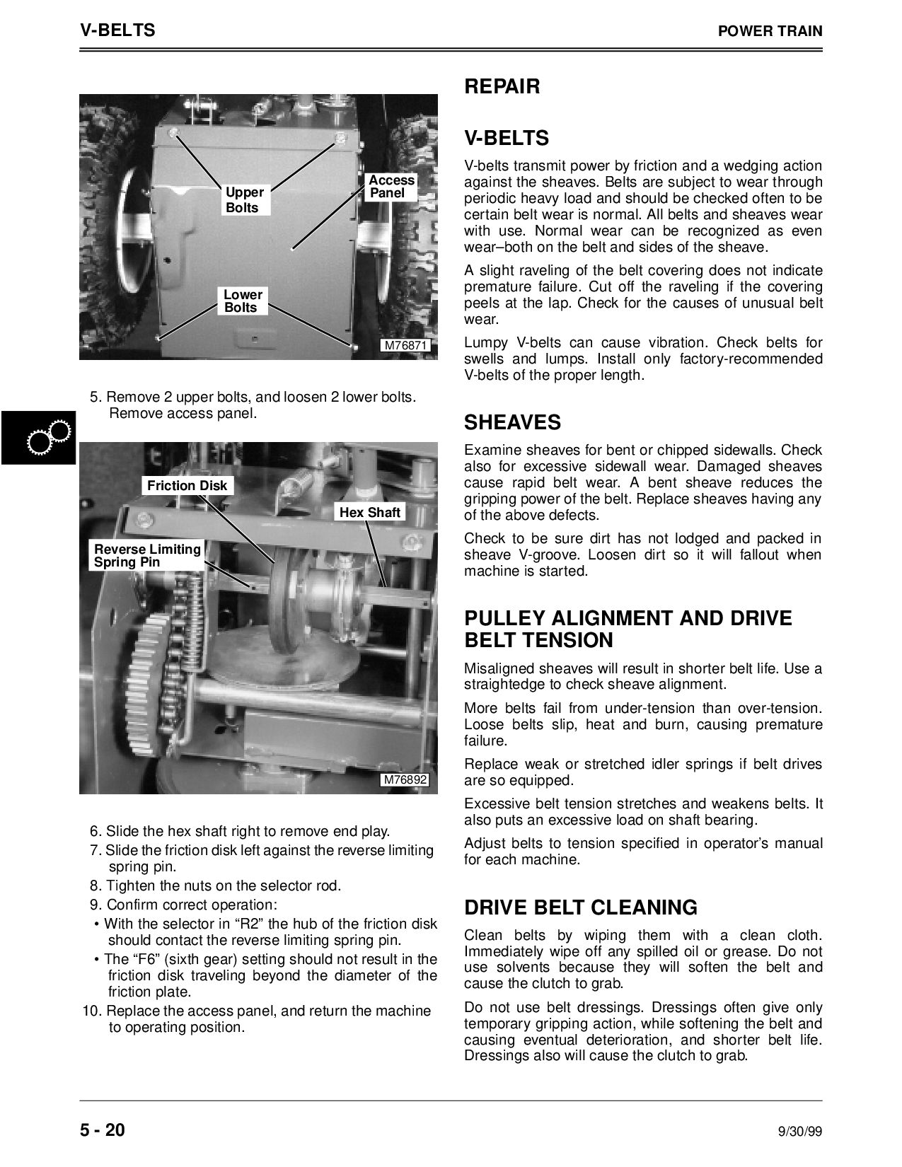
upper bolts, and loosen 2 lower bolts. Remove access panel. 6. Slide the hex shaft right to remove end play. 7. Slide the friction disk left against the reverse limiting spring pin. 8. Tighten the nuts on the selector rod. 9. Confirm correct operation: • With the selector in “R2” the hub of the friction disk should contact the reverse limiting spring pin. • The “F6” (sixth gear) setting should not result in the friction disk traveling beyond the diameter of the friction plate. 10. Replace the access panel, and return the machine to operating position. REPAIR V-BELTS V-belts transmit power by friction and a wedging action against the sheaves. Belts are subject to wear through periodic heavy load and should be checked often to be certain belt wear is normal. All belts and sheaves wear with use. Normal wear can be recognized as even wear–both on the belt and sides of the sheave. A slight raveling of the belt covering does not indicate premature failure. Cut off the raveling if the covering peels at the lap. Check for the causes of unusual belt wear. Lumpy V-belts can cause vibration. Check belts for swells and lumps. Install only factory-recommended V-belts of the proper length. SHEAVES Examine sheaves for bent or chipped sidewalls. Check also for excessive sidewall wear. Damaged sheaves cause rapid belt wear. A bent sheave reduces the gripping power of the belt. Replace sheaves having any of the above defects. Check to be sure dirt has not lodged and packed in sheave V-groove. Loosen dirt so it will fallout when machine is started. PULLEY ALIGNMENT AND DRIVE BELT TENSION Misaligned sheaves will result in shorter belt life. Use a straightedge to check sheave alignment. More belts fail from under-tension than over-tension. Loose belts slip, heat and burn, causing premature failure. Replace weak or stretched idler springs if belt drives are so equipped. Excessive belt tension stretches and weakens belts. It also puts an excessive load on shaft bearing. Adjust belts to tension specified in operator’s manual for each machine. DRIVE BELT CLEANING Clean belts by wiping them with a clean cloth. Immediately wipe off any spilled oil or grease. Do not use solvents because they will soften the belt and cause the clutch to grab. Do not use belt dressings. Dressings often give only temporary gripping action, while softening the belt and causing eventual deterioration, and shorter belt life. Dressings also will cause the clutch to grab. M76871 Upper Bolts Lower Bolts Access Panel M76892 Spring Pin Reverse Limiting Friction Disk Hex Shaft
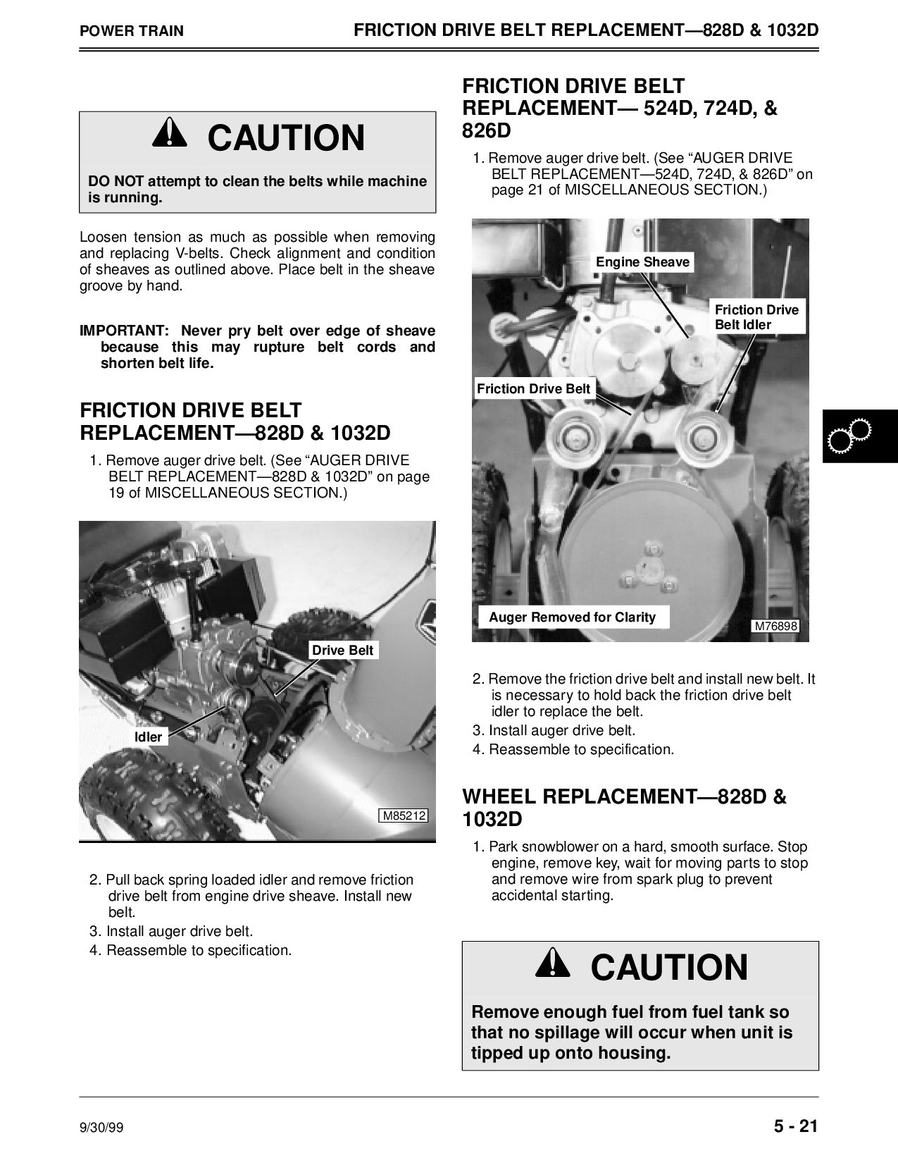
& 1032D Loosen tension as much as possible when removing and replacing V-belts. Check alignment and condition of sheaves as outlined above. Place belt in the sheave groove by hand. IMPORTANT: Never pry belt over edge of sheave because this may rupture belt cords and shorten belt life. FRICTION DRIVE BELT REPLACEMENT—828D & 1032D 1. Remove auger drive belt. (See “AUGER DRIVE BELT REPLACEMENT—828D & 1032D” on page 19 of MISCELLANEOUS SECTION.) 2. Pull back spring loaded idler and remove friction drive belt from engine drive sheave. Install new belt. 3. Install auger drive belt. 4. Reassemble to specification. FRICTION DRIVE BELT REPLACEMENT— 524D, 724D, & 826D 1. Remove auger drive belt. (See “AUGER DRIVE BELT REPLACEMENT—524D, 724D, & 826D” on page 21 of MISCELLANEOUS SECTION.) 2. Remove the friction drive belt and install new belt. It is necessary to hold back the friction drive belt idler to replace the belt. 3. Install auger drive belt. 4. Reassemble to specification. WHEEL REPLACEMENT—828D & 1032D 1. Park snowblower on a hard, smooth surface. Stop engine, remove key, wait for moving parts to stop and remove wire from spark plug to prevent accidental starting. c CAUTION DO NOT attempt to clean the belts while machine is running. M85212 Drive Belt Idler c CAUTION Remove enough fuel from fuel tank so that no spillage will occur when unit is tipped up onto housing. M76898 Auger Removed for Clarity Friction Drive Belt Idler Engine Sheave Friction Drive Belt
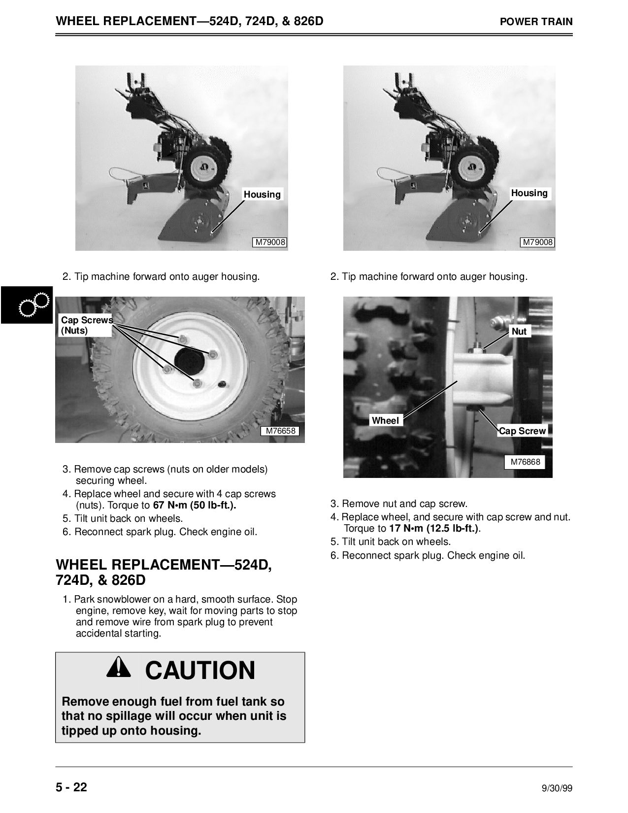
TRAIN 2. Tip machine forward onto auger housing. 3. Remove cap screws (nuts on older models) securing wheel. 4. Replace wheel and secure with 4 cap screws (nuts). Torque to 67 N•m (50 lb-ft.). 5. Tilt unit back on wheels. 6. Reconnect spark plug. Check engine oil. WHEEL REPLACEMENT—524D, 724D, & 826D 1. Park snowblower on a hard, smooth surface. Stop engine, remove key, wait for moving parts to stop and remove wire from spark plug to prevent accidental starting. 2. Tip machine forward onto auger housing. 3. Remove nut and cap screw. 4. Replace wheel, and secure with cap screw and nut. Torque to 17 N•m (12.5 lb-ft.). 5. Tilt unit back on wheels. 6. Reconnect spark plug. Check engine oil. c CAUTION Remove enough fuel from fuel tank so that no spillage will occur when unit is tipped up onto housing. M79008 Housing M76658 (Nuts) Cap Screws M79008 Housing M76868 Nut Cap Screw Wheel


 sxedcwrfvk
 tomoyanonymous
 frankvandijk
 moore
 inesmontani
 codingconduct
 thekraken
 raygrieselhuber
 marketingsoph
 aleyda
 jnunemaker
 matthewcrist