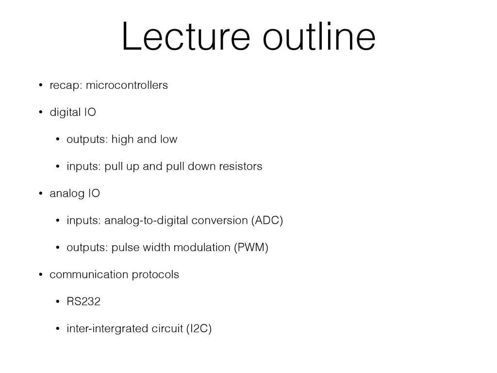
high and low • inputs: pull up and pull down resistors • analog IO • inputs: analog-to-digital conversion (ADC) • outputs: pulse width modulation (PWM) • communication protocols • RS232 • inter-intergrated circuit (I2C)
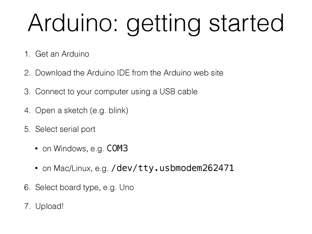
Arduino IDE from the Arduino web site 3. Connect to your computer using a USB cable 4. Open a sketch (e.g. blink) 5. Select serial port • on Windows, e.g. COM3 • on Mac/Linux, e.g. /dev/tty.usbmodem262471 6. Select board type, e.g. Uno 7. Upload!
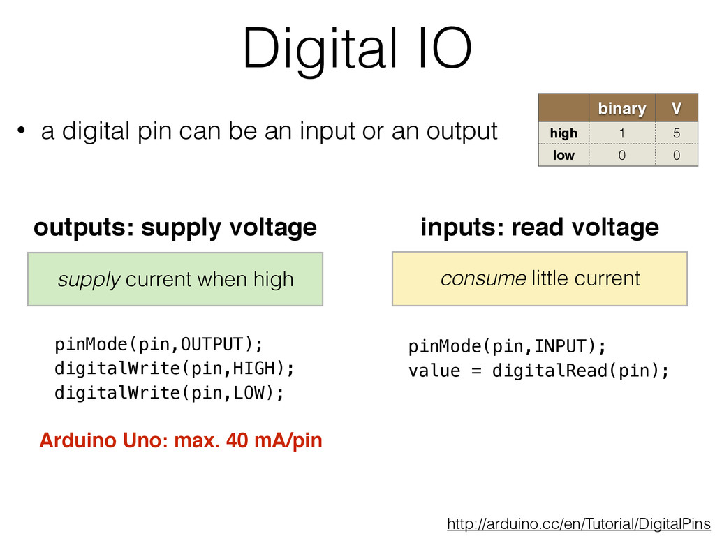
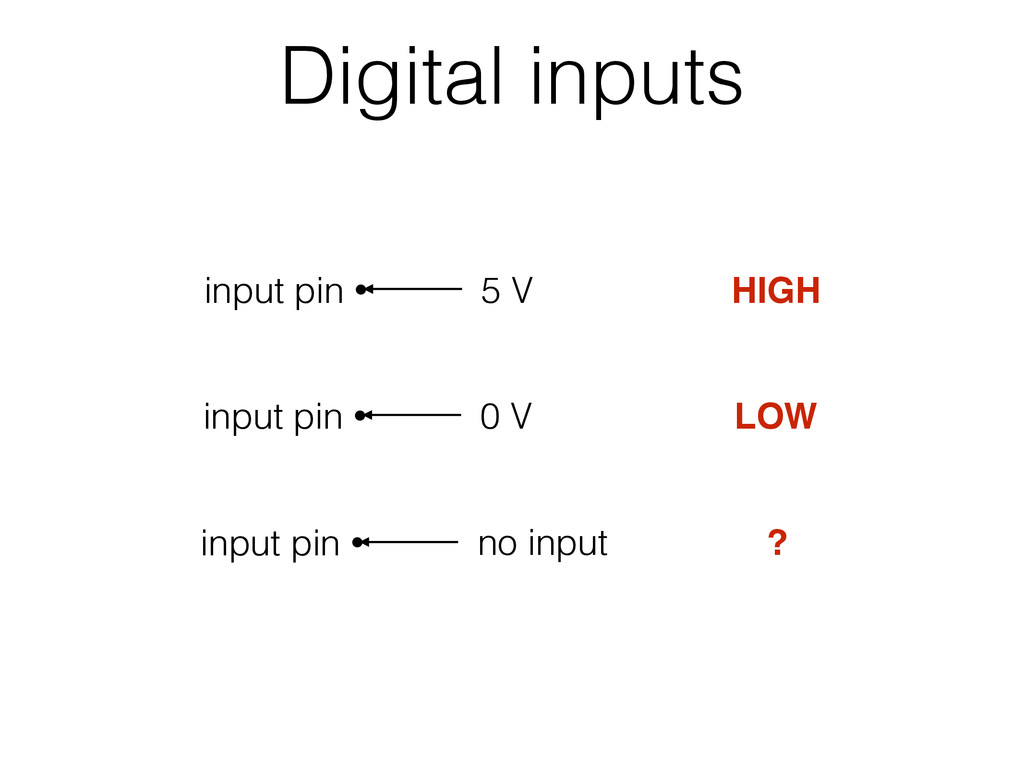
• a digital pin can be an input or an output inputs: read voltage consume little current outputs: supply voltage supply current when high Arduino Uno: max. 40 mA/pin pinMode(pin,INPUT); value = digitalRead(pin); pinMode(pin,OUTPUT); digitalWrite(pin,HIGH); digitalWrite(pin,LOW); http://arduino.cc/en/Tutorial/DigitalPins
digitalRead(pin) 5 V high GND low neither high use to steer inputs to known state when no input is present pinMode(pin,INPUT_PULLUP) Arduino has internal pull up resistors: switch digitalRead(pin) 5 V high GND low neither low GND input pin 10 kΩ pull down input pin 10 kΩ
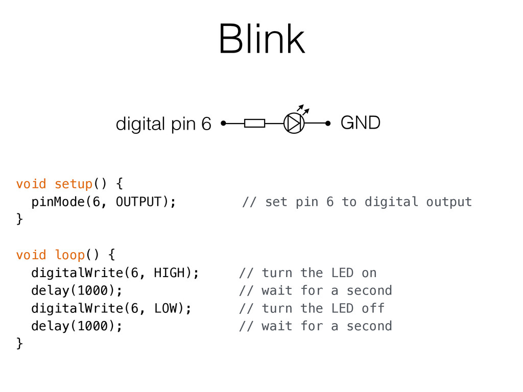
to digital output } void loop() { digitalWrite(6, HIGH); // turn the LED on delay(1000); // wait for a second digitalWrite(6, LOW); // turn the LED off delay(1000); // wait for a second } digital pin 6 GND
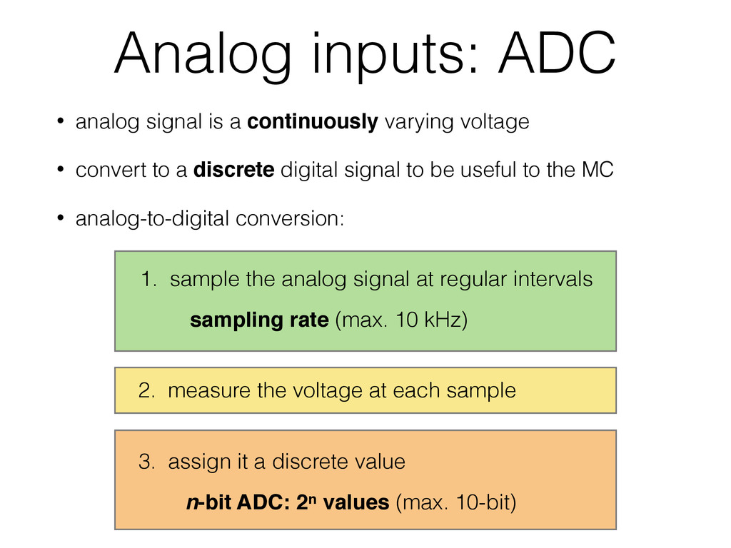
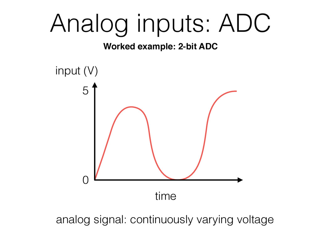
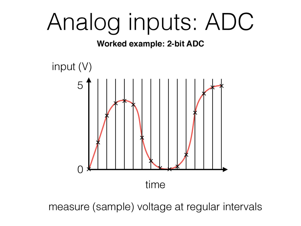
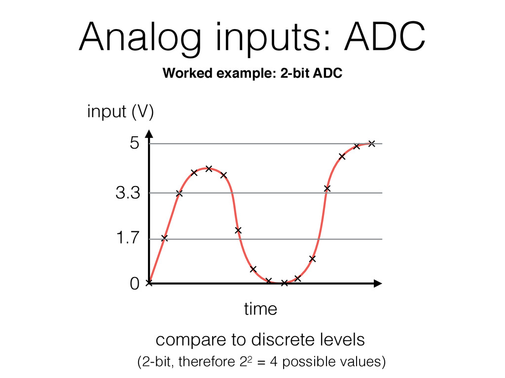
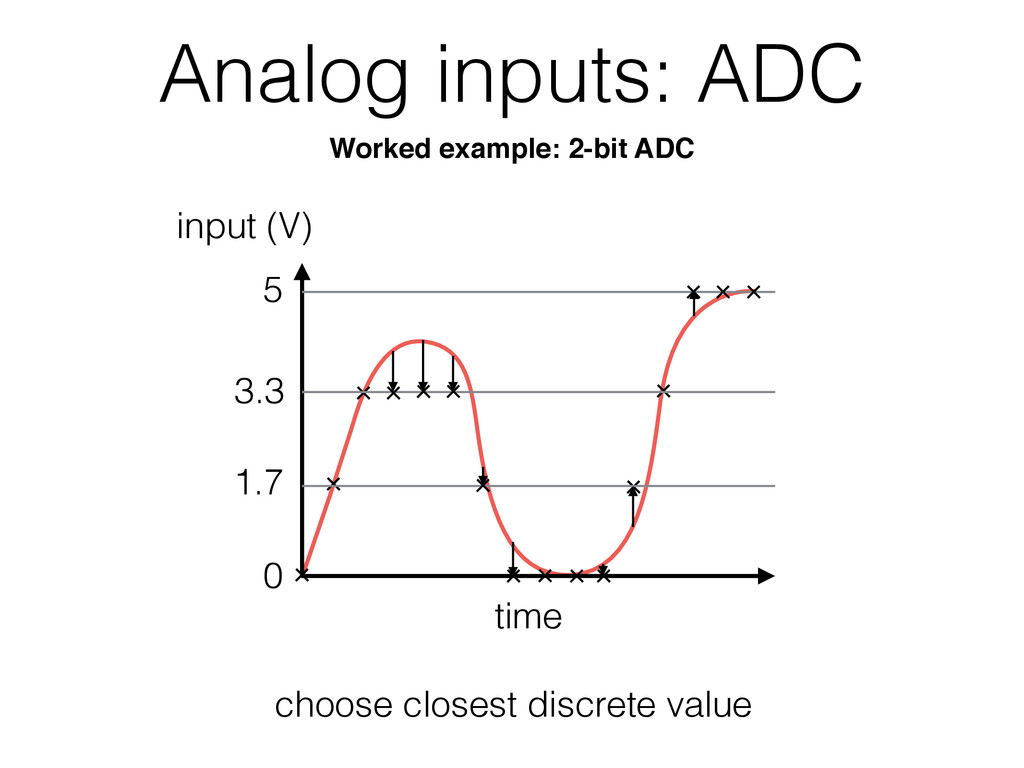
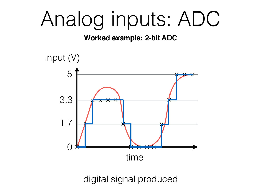
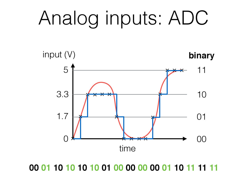
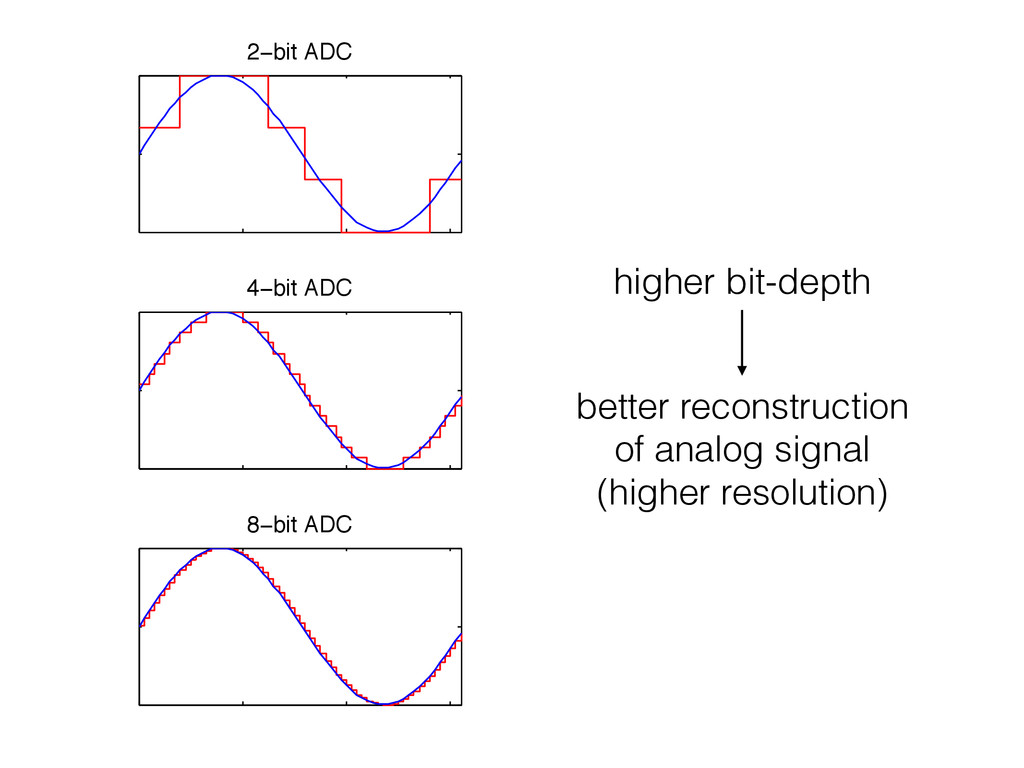
voltage • convert to a discrete digital signal to be useful to the MC • analog-to-digital conversion: 1. sample the analog signal at regular intervals sampling rate (max. 10 kHz) 2. measure the voltage at each sample n-bit ADC: 2n values (max. 10-bit) 3. assign it a discrete value
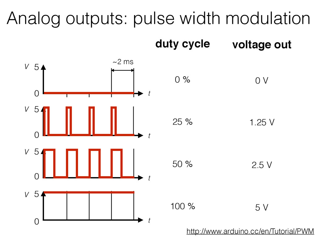
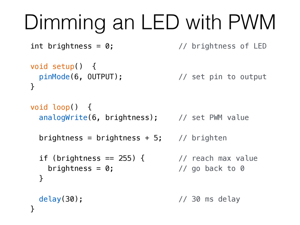
brightness of LED void setup() { pinMode(6, OUTPUT); // set pin to output } void loop() { analogWrite(6, brightness); // set PWM value brightness = brightness + 5; // brighten if (brightness == 255) { // reach max value brightness = 0; // go back to 0 } delay(30); // 30 ms delay }
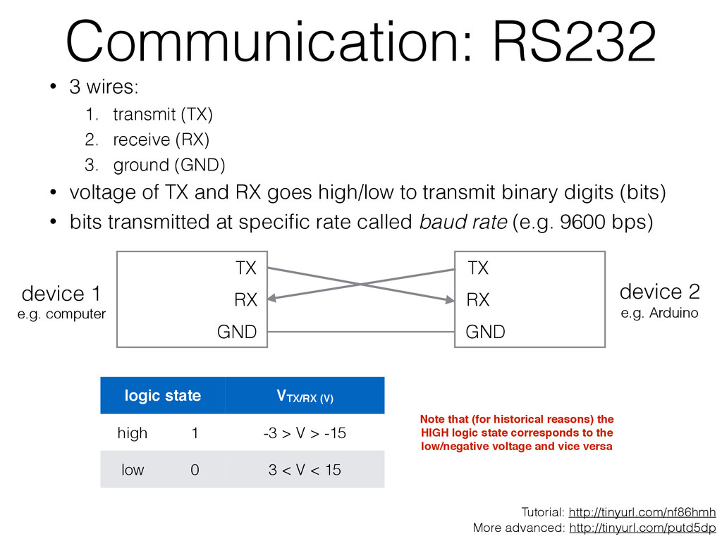
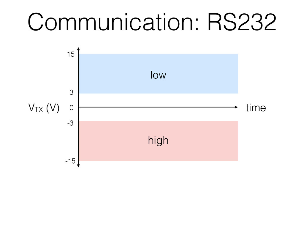
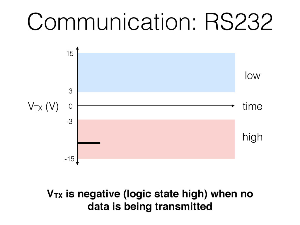
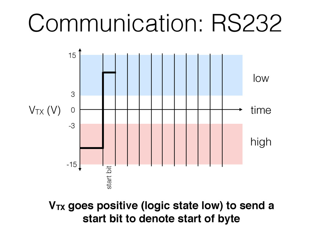
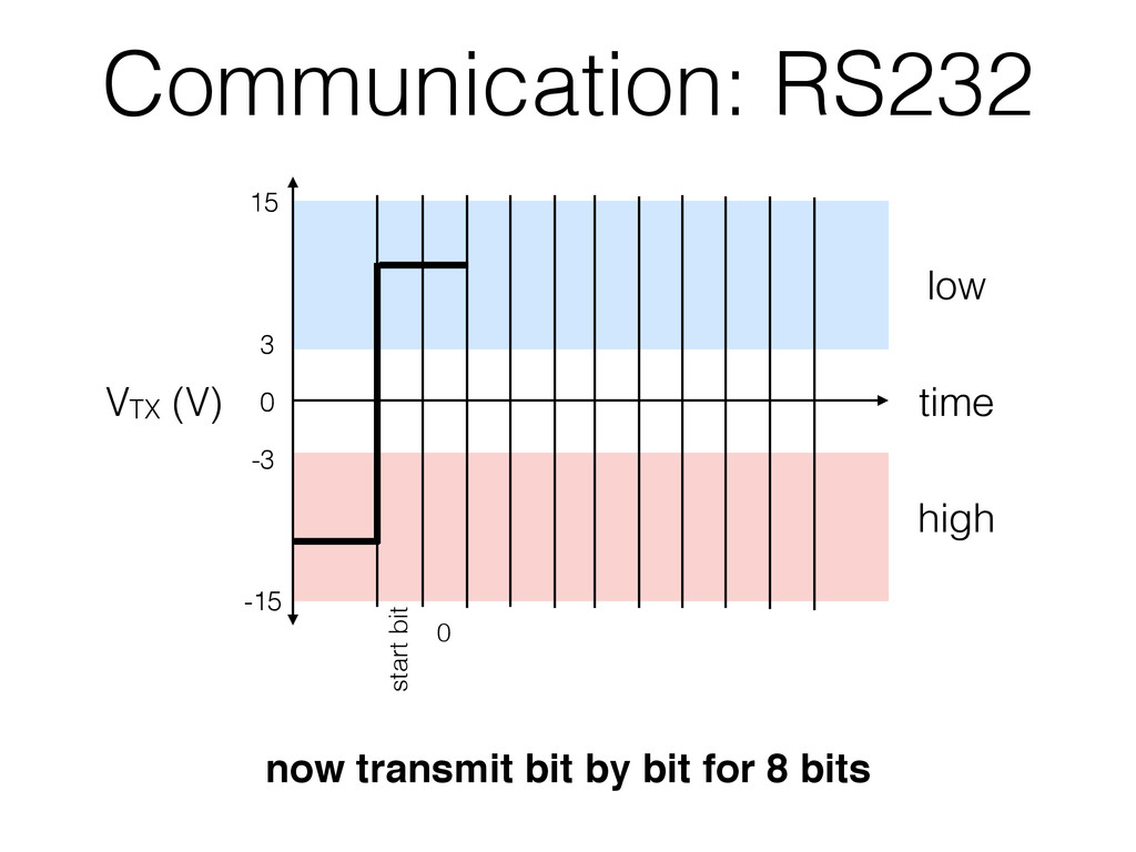
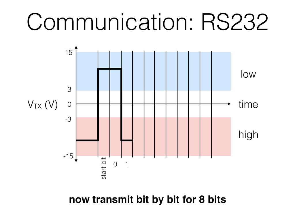
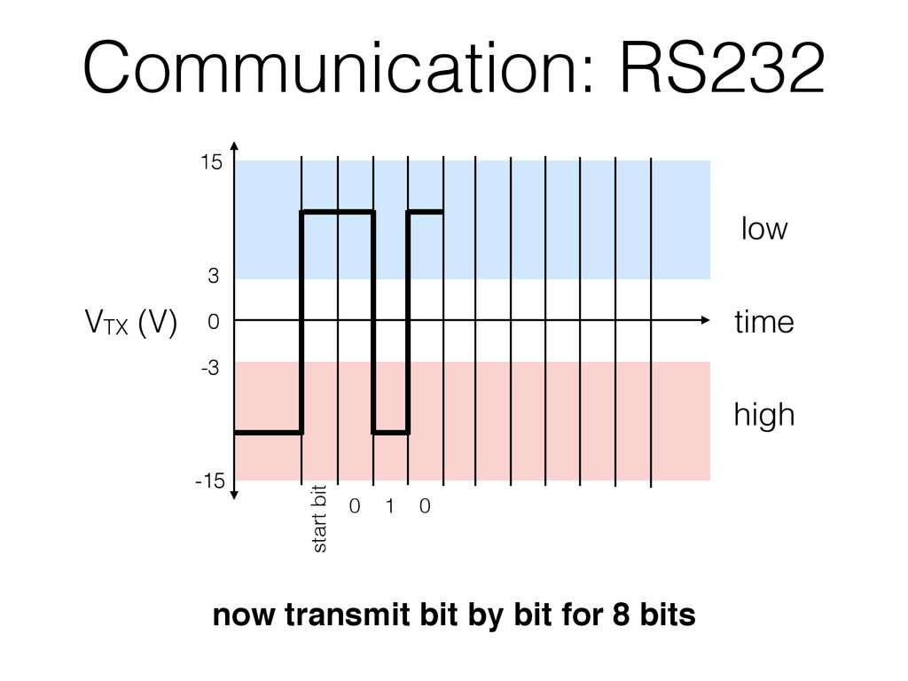
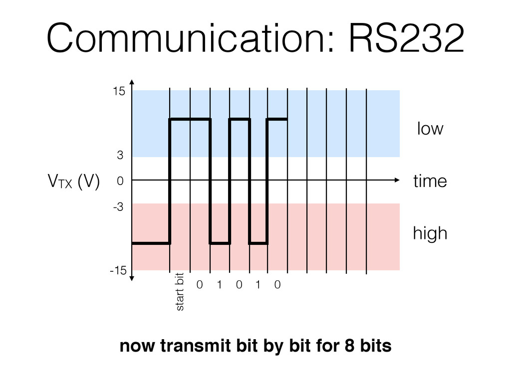
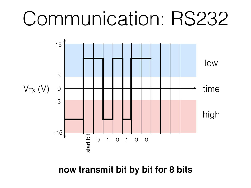
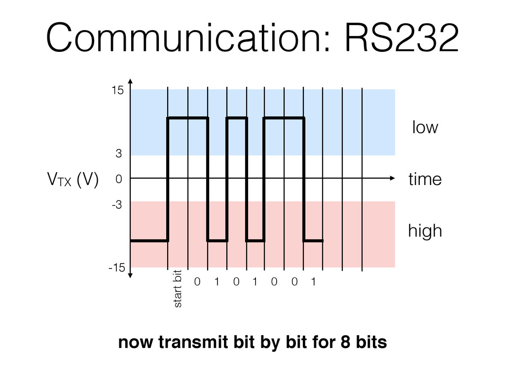
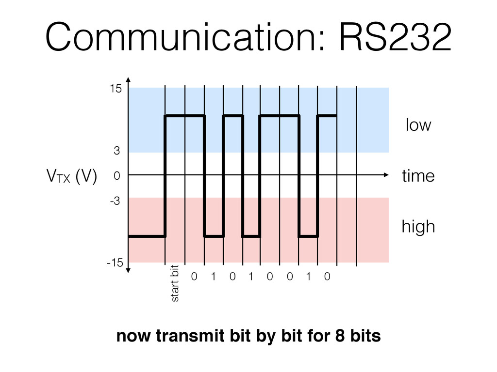
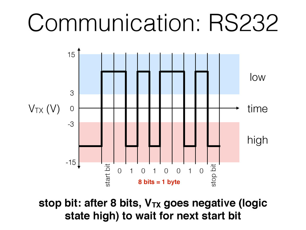
TX GND device 2 e.g. Arduino • 3 wires: 1. transmit (TX) 2. receive (RX) 3. ground (GND) • voltage of TX and RX goes high/low to transmit binary digits (bits) • bits transmitted at specific rate called baud rate (e.g. 9600 bps) logic state VTX/RX (V) high 1 -3 > V > -15 low 0 3 < V < 15 Note that (for historical reasons) the HIGH logic state corresponds to the low/negative voltage and vice versa Tutorial: http://tinyurl.com/nf86hmh More advanced: http://tinyurl.com/putd5dp
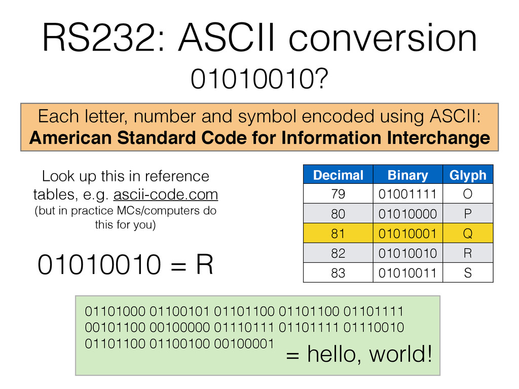
using ASCII: American Standard Code for Information Interchange Look up this in reference tables, e.g. ascii-code.com (but in practice MCs/computers do this for you) 01101000 01100101 01101100 01101100 01101111 00101100 00100000 01110111 01101111 01110010 01101100 01100100 00100001 = hello, world! 01010010 = R Decimal Binary Glyph 79 01001111 O 80 01010000 P 81 01010001 Q 82 01010010 R 83 01010011 S
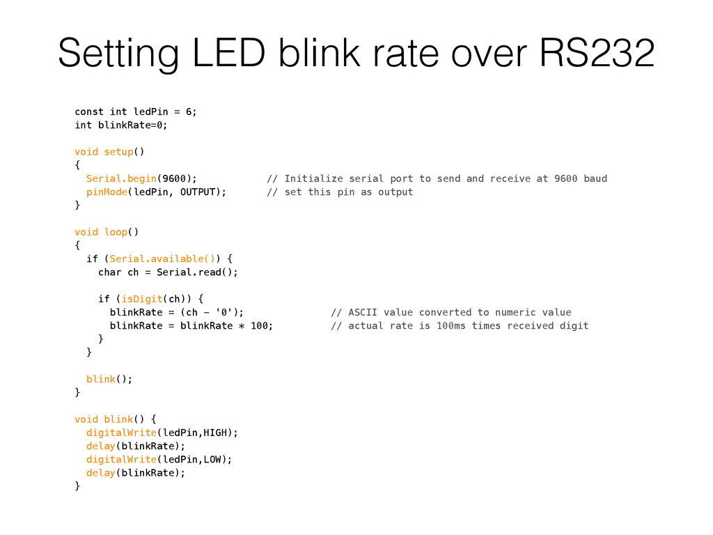
6; int blinkRate=0; void setup() { Serial.begin(9600); // Initialize serial port to send and receive at 9600 baud pinMode(ledPin, OUTPUT); // set this pin as output } void loop() { if (Serial.available()) { char ch = Serial.read(); if (isDigit(ch)) { blinkRate = (ch - '0'); // ASCII value converted to numeric value blinkRate = blinkRate * 100; // actual rate is 100ms times received digit } } blink(); } void blink() { digitalWrite(ledPin,HIGH); delay(blinkRate); digitalWrite(ledPin,LOW); delay(blinkRate); }