gravitational wave interferometers Ed Daw - University of Sheffield On behalf of the LIGO Scientific Collaboration and the Virgo collaboration (LVC): http://apod.nasa.gov/apod/image/0809/sn1006_hst_big.jpg LIGO-G080641-00-K
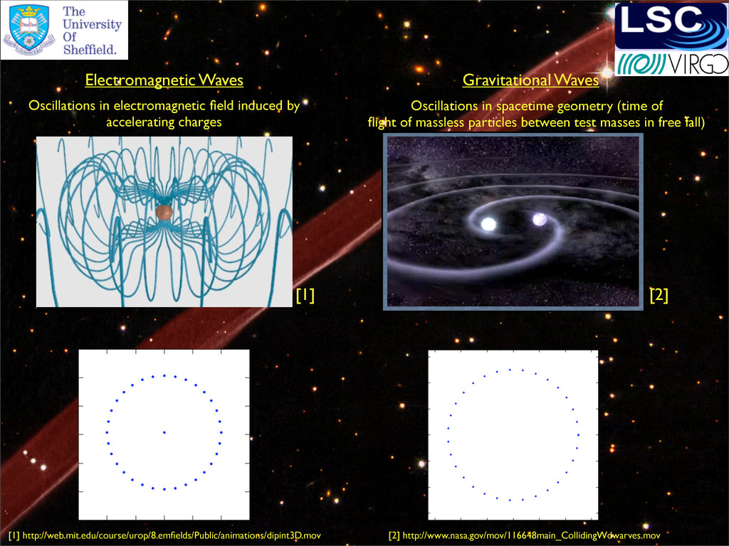
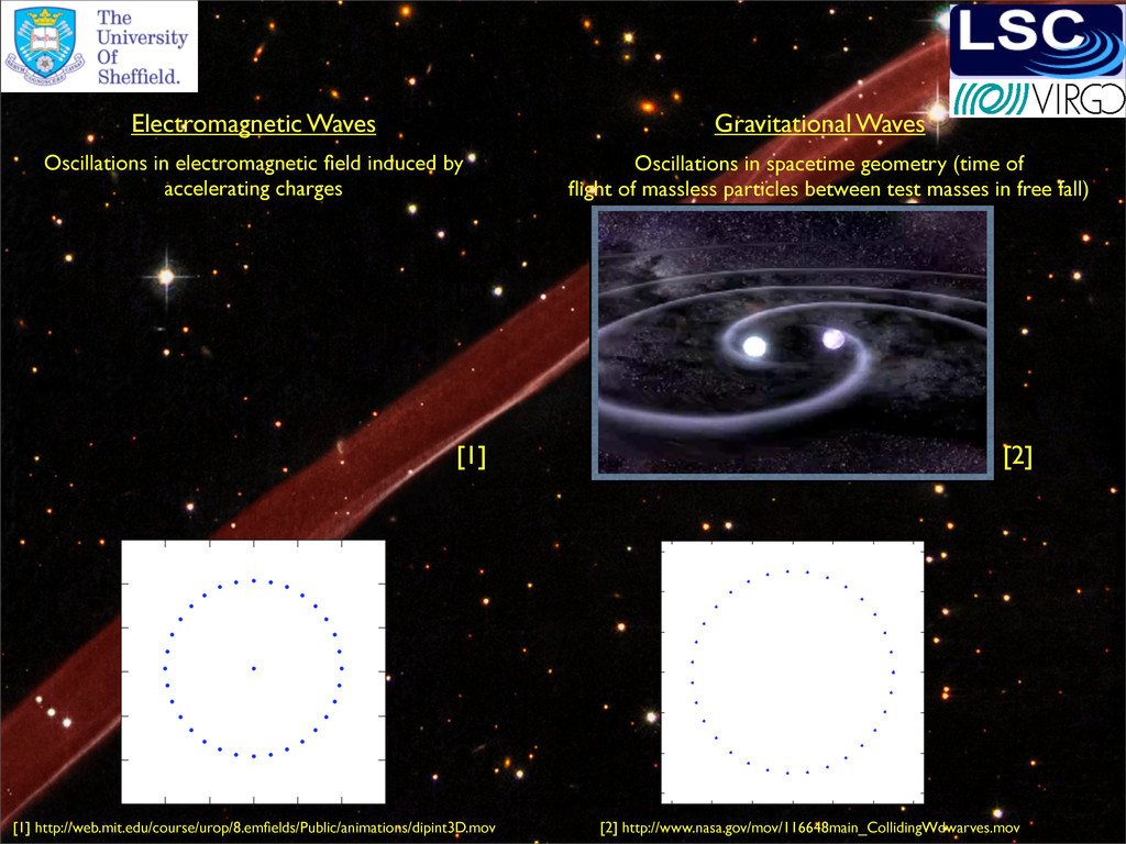
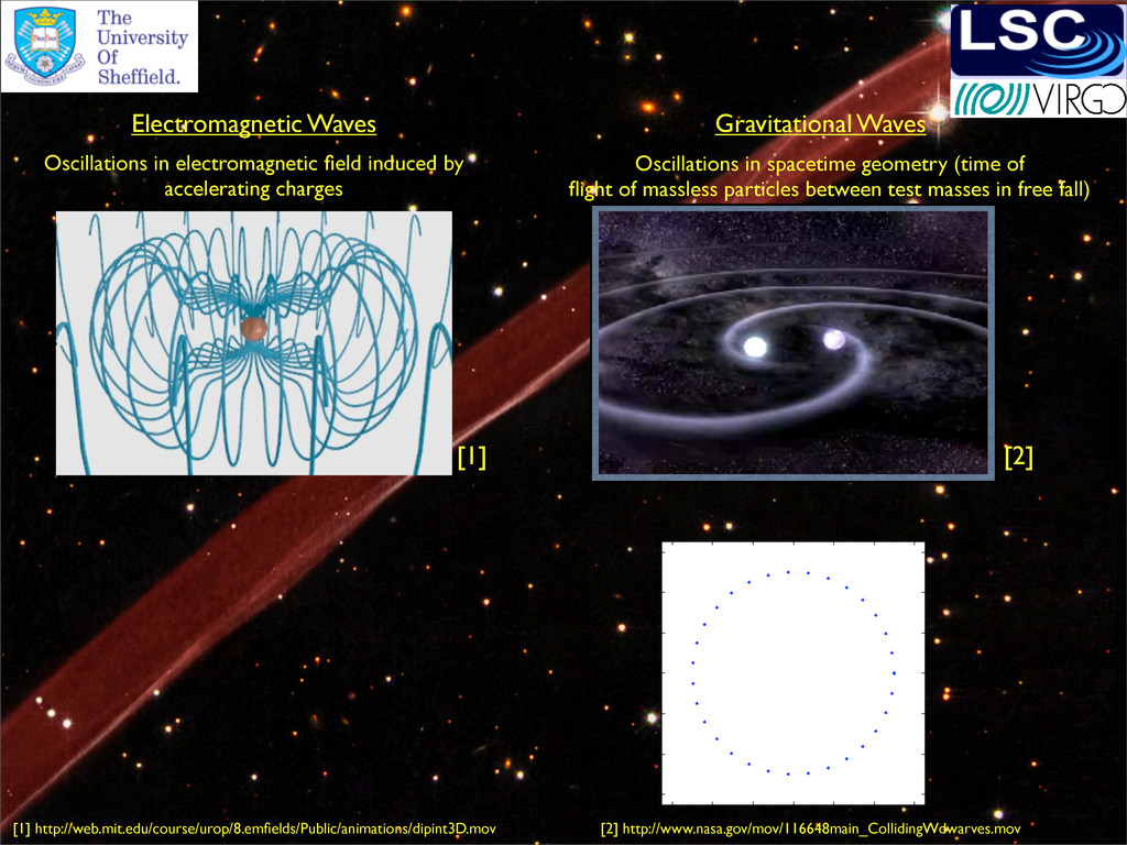
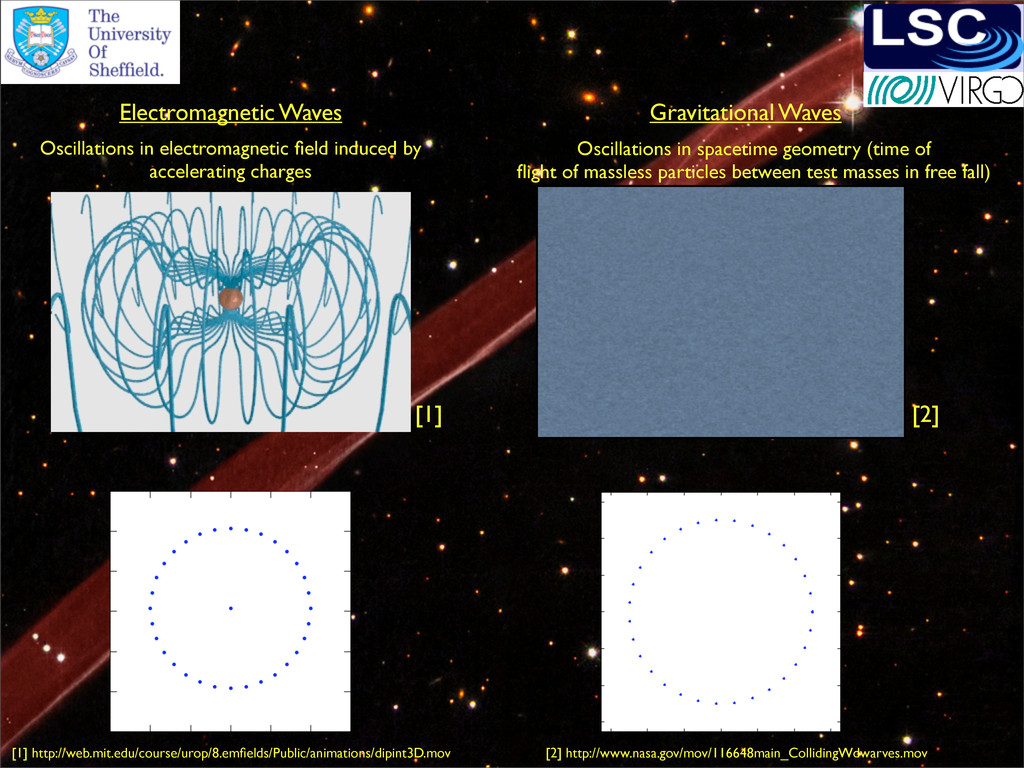
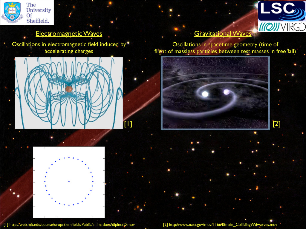
Oscillations in spacetime geometry (time of flight of massless particles between test masses in free fall) Gravitational Waves [1] [2] [1] http://web.mit.edu/course/urop/8.emfields/Public/animations/dipint3D.mov [2] http://www.nasa.gov/mov/116648main_CollidingWdwarves.mov
Oscillations in spacetime geometry (time of flight of massless particles between test masses in free fall) Gravitational Waves [1] [2] [1] http://web.mit.edu/course/urop/8.emfields/Public/animations/dipint3D.mov [2] http://www.nasa.gov/mov/116648main_CollidingWdwarves.mov
Oscillations in spacetime geometry (time of flight of massless particles between test masses in free fall) Gravitational Waves [1] [2] [1] http://web.mit.edu/course/urop/8.emfields/Public/animations/dipint3D.mov [2] http://www.nasa.gov/mov/116648main_CollidingWdwarves.mov
Oscillations in spacetime geometry (time of flight of massless particles between test masses in free fall) Gravitational Waves [1] [2] [1] http://web.mit.edu/course/urop/8.emfields/Public/animations/dipint3D.mov [2] http://www.nasa.gov/mov/116648main_CollidingWdwarves.mov
Oscillations in spacetime geometry (time of flight of massless particles between test masses in free fall) Gravitational Waves [1] [2] [1] http://web.mit.edu/course/urop/8.emfields/Public/animations/dipint3D.mov [2] http://www.nasa.gov/mov/116648main_CollidingWdwarves.mov
Oscillations in spacetime geometry (time of flight of massless particles between test masses in free fall) Gravitational Waves [1] [2] [1] http://web.mit.edu/course/urop/8.emfields/Public/animations/dipint3D.mov [2] http://www.nasa.gov/mov/116648main_CollidingWdwarves.mov
Oscillations in spacetime geometry (time of flight of massless particles between test masses in free fall) Gravitational Waves [1] [2] [1] http://web.mit.edu/course/urop/8.emfields/Public/animations/dipint3D.mov [2] http://www.nasa.gov/mov/116648main_CollidingWdwarves.mov
Oscillations in spacetime geometry (time of flight of massless particles between test masses in free fall) Gravitational Waves [1] [2] [1] http://web.mit.edu/course/urop/8.emfields/Public/animations/dipint3D.mov [2] http://www.nasa.gov/mov/116648main_CollidingWdwarves.mov
Oscillations in spacetime geometry (time of flight of massless particles between test masses in free fall) Gravitational Waves [1] [2] [1] http://web.mit.edu/course/urop/8.emfields/Public/animations/dipint3D.mov [2] http://www.nasa.gov/mov/116648main_CollidingWdwarves.mov
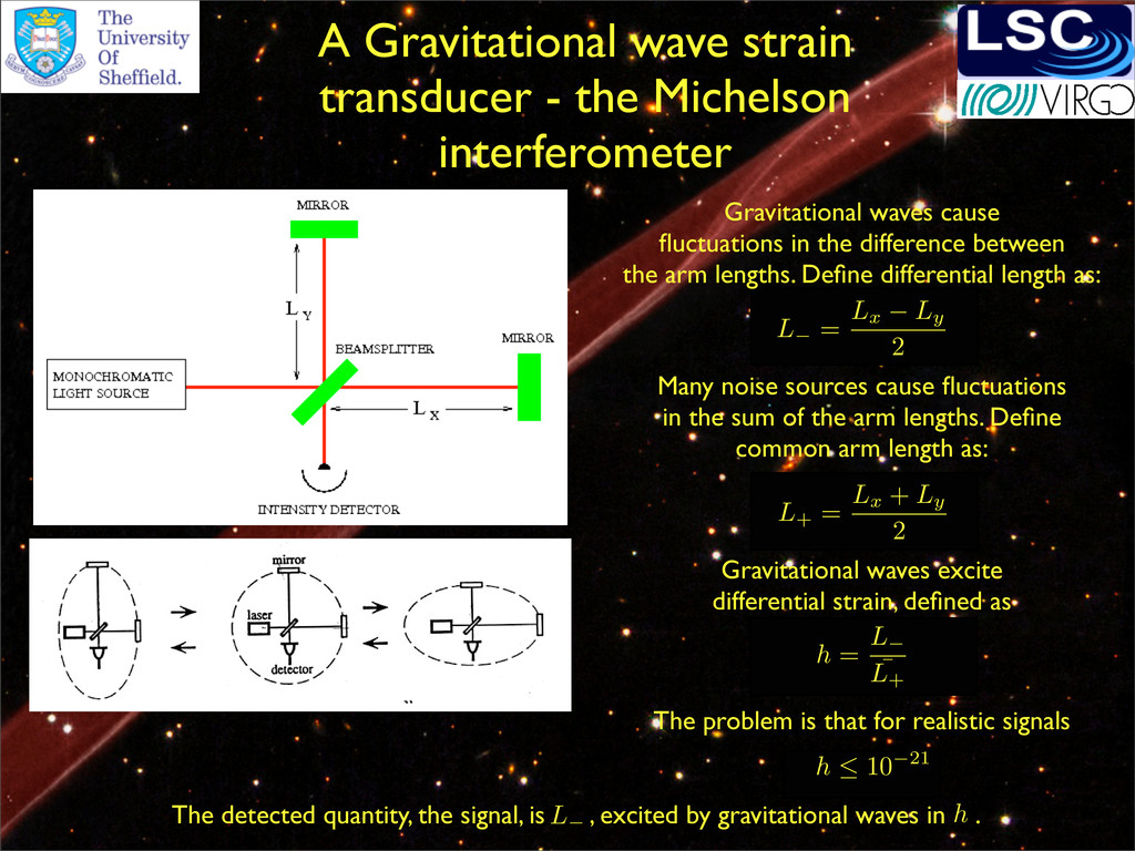
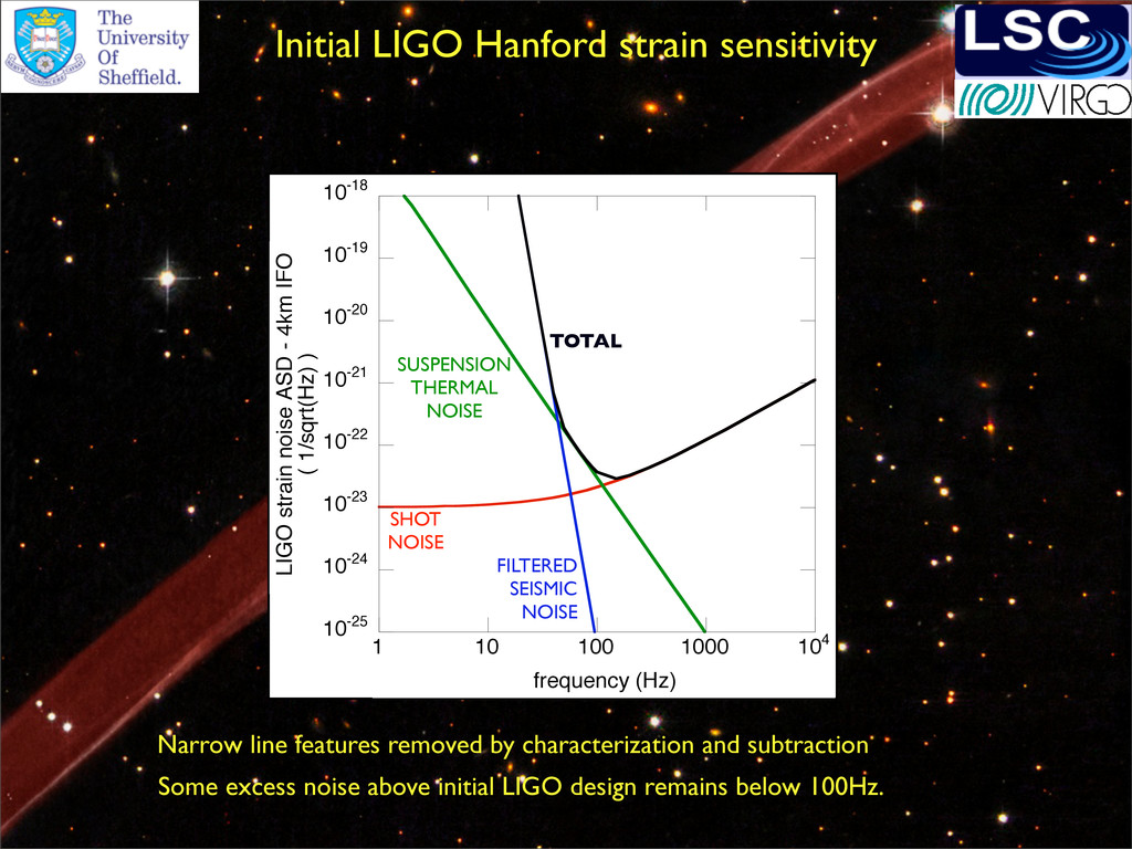
waves cause fluctuations in the difference between the arm lengths. Define differential length as: Many noise sources cause fluctuations in the sum of the arm lengths. Define common arm length as: L− = Lx − Ly 2 L+ = Lx + Ly 2 Gravitational waves excite differential strain, defined as h = L− ¯ L+ The problem is that for realistic signals h ≤ 10−21 The detected quantity, the signal, is , excited by gravitational waves in . L− h
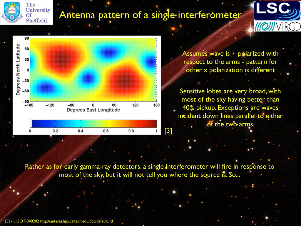
broad, with most of the sky having better than 40% pickup. Exceptions are waves incident down lines parallel to either of the two arms. Assumes wave is + polarized with respect to the arms - pattern for other x polarization is different [3] [3] - LIGO T-040202 http://antares.ligo.caltech.edu/dcc/default.htf Rather as for early gamma-ray detectors, a single interferometer will fire in response to most of the sky, but it will not tell you where the source is. So...
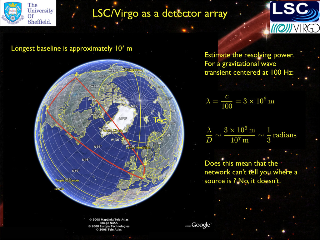
107 m Estimate the resolving power. For a gravitational wave transient centered at 100 Hz: Does this mean that the network can’t tell you where a source is ? No, it doesn’t. λ = c 100 = 3 × 10⁶ m λ D ∼ 3 × 10⁶ m 107 m ∼ 1 3 radians
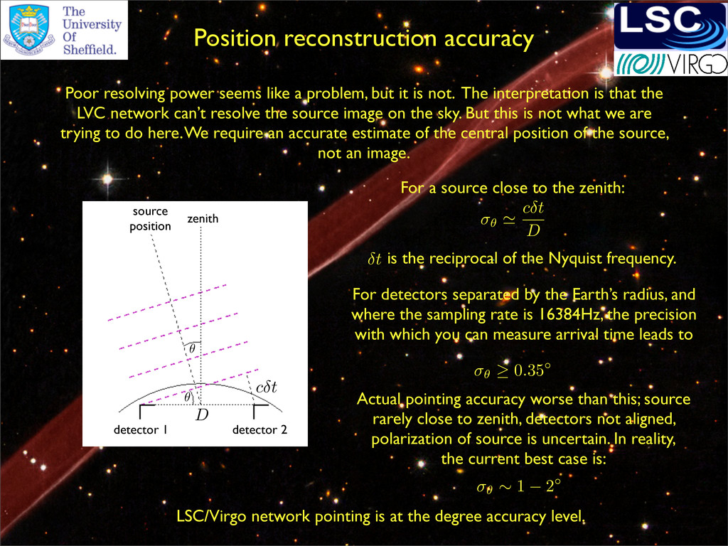
but it is not. The interpretation is that the LVC network can’t resolve the source image on the sky. But this is not what we are trying to do here. We require an accurate estimate of the central position of the source, not an image. zenith source position cδt detector 1 detector 2 D θ θ For a source close to the zenith: is the reciprocal of the Nyquist frequency. For detectors separated by the Earth’s radius, and where the sampling rate is 16384Hz, the precision with which you can measure arrival time leads to Actual pointing accuracy worse than this; source rarely close to zenith, detectors not aligned, polarization of source is uncertain. In reality, the current best case is: σθ cδt D δt σθ ≥ 0.35◦ σθ ∼ 1 − 2◦ LSC/Virgo network pointing is at the degree accuracy level.
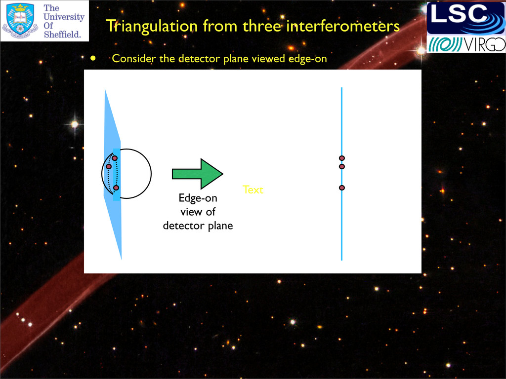
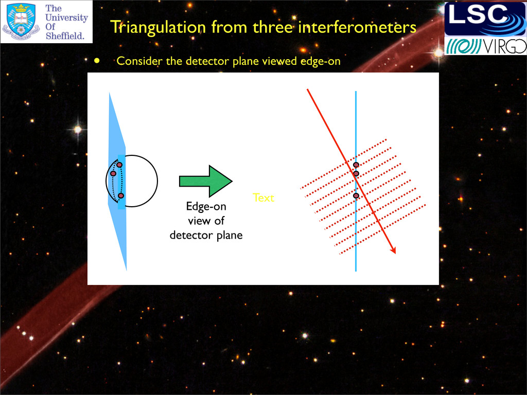
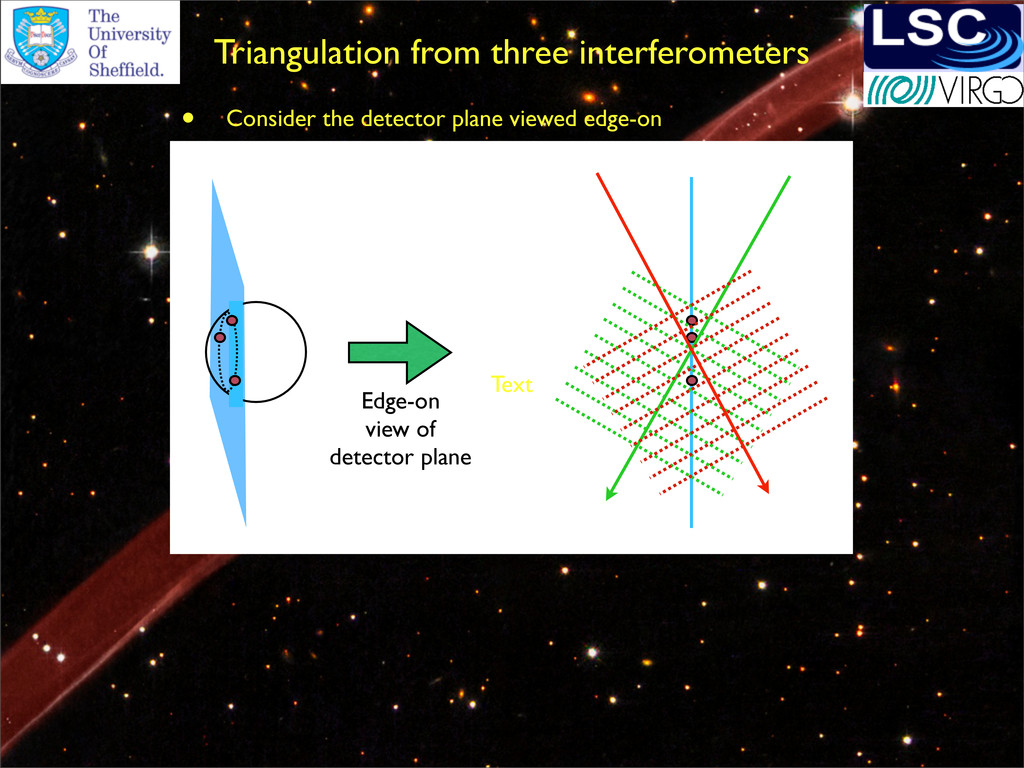
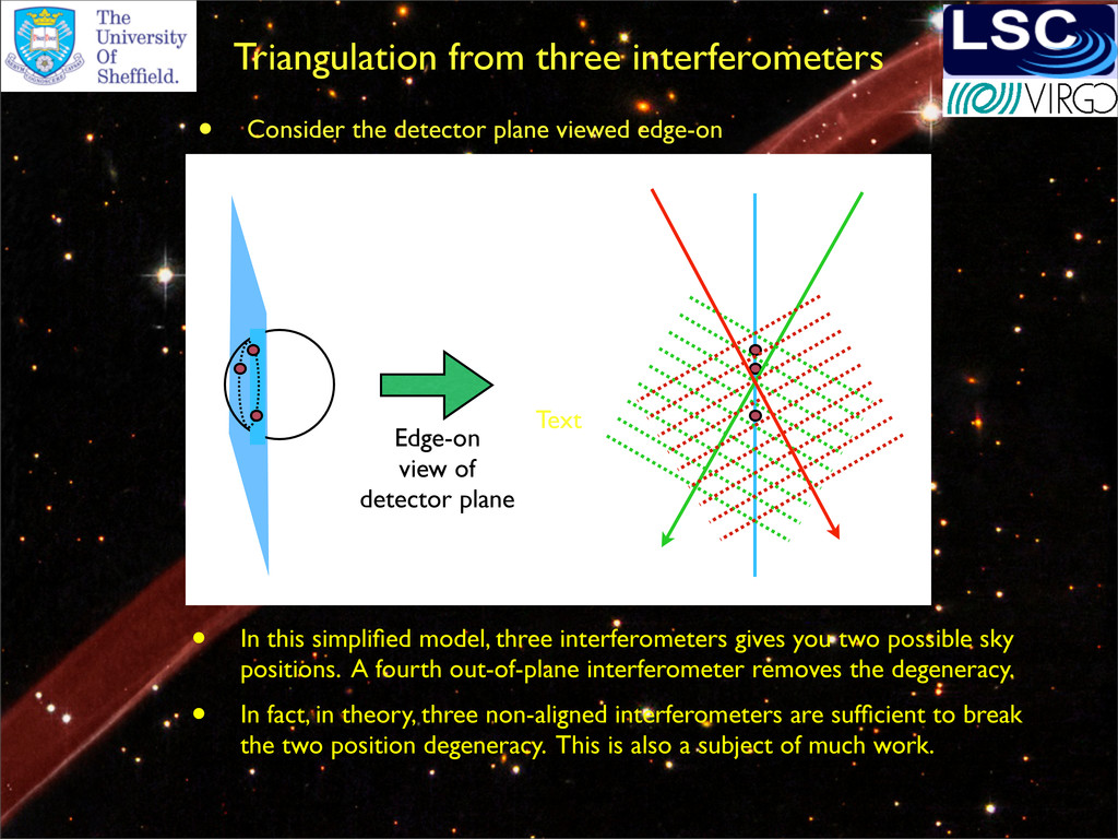
Consider the detector plane viewed edge-on Text • In this simplified model, three interferometers gives you two possible sky positions. A fourth out-of-plane interferometer removes the degeneracy.
Consider the detector plane viewed edge-on Text • In this simplified model, three interferometers gives you two possible sky positions. A fourth out-of-plane interferometer removes the degeneracy. • In fact, in theory, three non-aligned interferometers are sufficient to break the two position degeneracy. This is also a subject of much work.
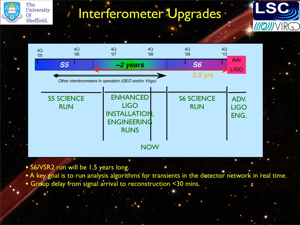
4Q ʻ08 4Q ʻ10 4Q ʻ09 Adv LIGO ~2 years Other interferometers in operation (GEO and/or Virgo) 3.5 yrs NOW ENHANCED LIGO INSTALLATION, ENGINEERING RUNS S6 SCIENCE RUN ADV. LIGO ENG. S5 SCIENCE RUN • S6/VSR2 run will be 1.5 years long. • A key goal is to run analysis algorithms for transients in the detector network in real time. • Group delay from signal arrival to reconstruction <30 mins.
vibration isolation at both sites • High Q compound pendulum suspensions • 40kg optics to reduce radiation pressure noise • Signal recycling mirror for narrowbanding • Parallel comparable upgrades to Virgo Approved by N.S.F. in U.S. Quad suspension prototype (U.K.) 180W laser amplifier prototype (Germany) HEPI hydraulic actuator
of understanding (MOU) between LSC/Virgo and any external collaborator before cooperative efforts can commence. • Collaboration is between the whole LSC/Virgo collaboration and the external entity, not just individual members of LSC/Virgo. • Collaboration must be for an identified purpose. • No collaborations guaranteeing exclusivity are permitted. • MOU must include agreeement of the model for data sharing between the collaborating entitites. • MOU must include statements of policies on joint publication of results / limits / technical work. LSC and Virgo scientists are very keen to collaborate with other entities. External entity could be an individual (astronomer with target of opportunity observing time, for example), a working group, or a facility - decided on a case-by-case basis. External collaborations are one of the best paths to exciting science with LSC / Virgo interferometers. Some guidelines for setting up collaborations.
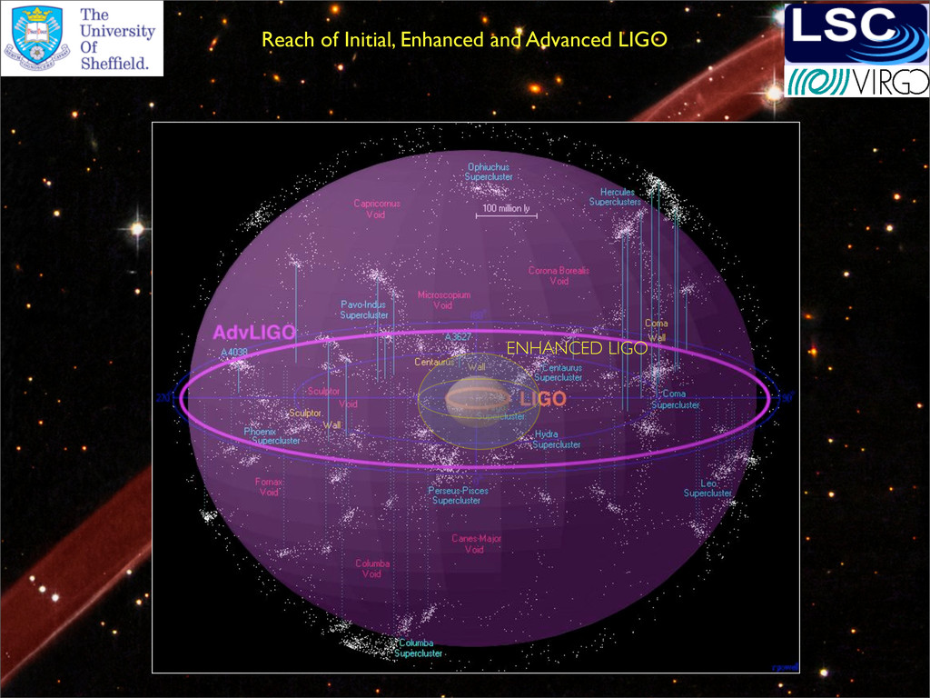
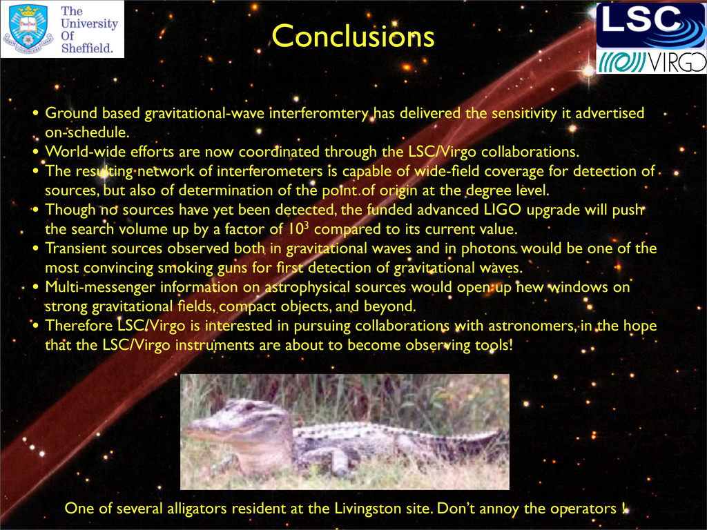
it advertised on-schedule. • World-wide efforts are now coordinated through the LSC/Virgo collaborations. • The resulting network of interferometers is capable of wide-field coverage for detection of sources, but also of determination of the point of origin at the degree level. • Though no sources have yet been detected, the funded advanced LIGO upgrade will push the search volume up by a factor of 103 compared to its current value. • Transient sources observed both in gravitational waves and in photons would be one of the most convincing smoking guns for first detection of gravitational waves. • Multi-messenger information on astrophysical sources would open up new windows on strong gravitational fields, compact objects, and beyond. • Therefore LSC/Virgo is interested in pursuing collaborations with astronomers, in the hope that the LSC/Virgo instruments are about to become observing tools! One of several alligators resident at the Livingston site. Don’t annoy the operators !