Upgrade to Pro — share decks privately, control downloads, hide ads and more …

Caterpillar_Cat_D6N_TRACK-TYPE_TRACTOR__Prefix_...

dcrfqdcnvk
May 21, 2024
7

 Caterpillar_Cat_D6N_TRACK-TYPE_TRACTOR__Prefix_LJR__Service_Repair_Manual__LJR00001_and_up_.pdf

dcrfqdcnvk

May 21, 2024
Tweet

More Decks by dcrfqdcnvk

Transcript

  1. Shutdown SIS Previous Screen Product: TRACK-TYPE TRACTOR Model: D6N TRACK-TYPE

    TRACTOR LJR Configuration: D6N XL Differential Steering, Electrohydraulic Implement TRACK-TYPE TRACTOR LJR00001-UP (MACHINE) POWERED BY C6.6 Engine Disassembly and Assembly C6.6 Engines for Caterpillar Built Machines Media Number -KENR6081-15 Publication Date -01/03/2014 Date Updated -04/03/2014 i02786807 Valve Mechanism Cover - Remove and Install SMCS - 1107-010 Removal Procedure NOTICE Keep all parts clean from contaminants. Contaminants may cause rapid wear and shortened component life. Illustration 1 g01342429 Typical example
  2. 1. Disconnect the breather hose from the separator for the

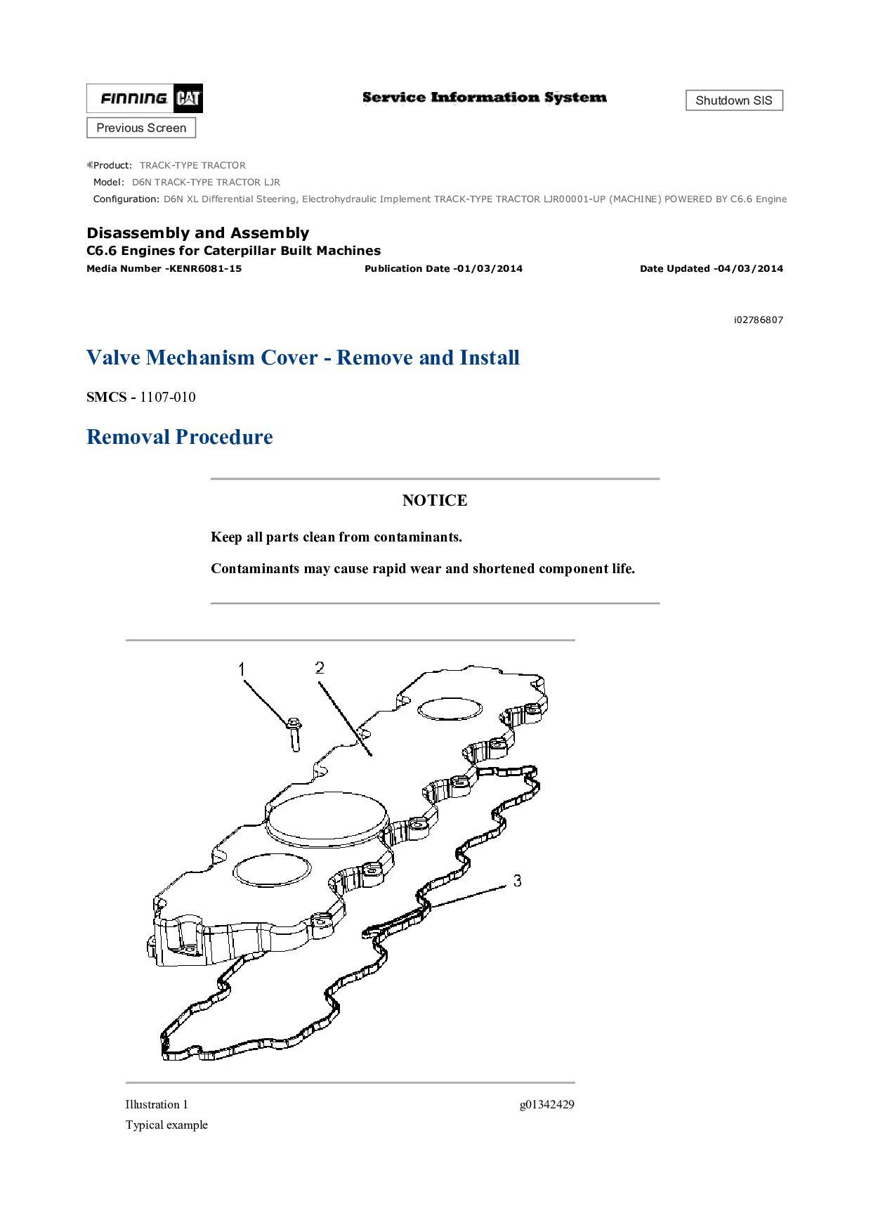
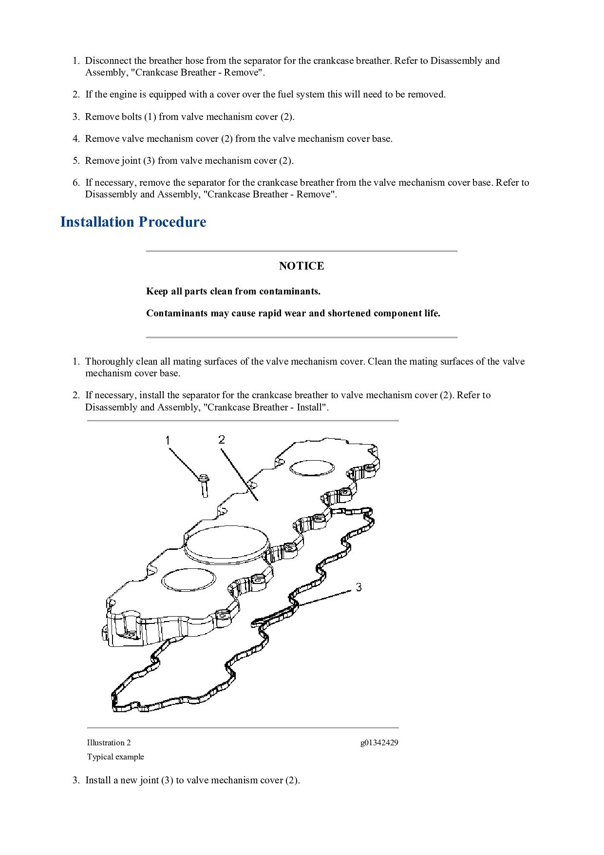
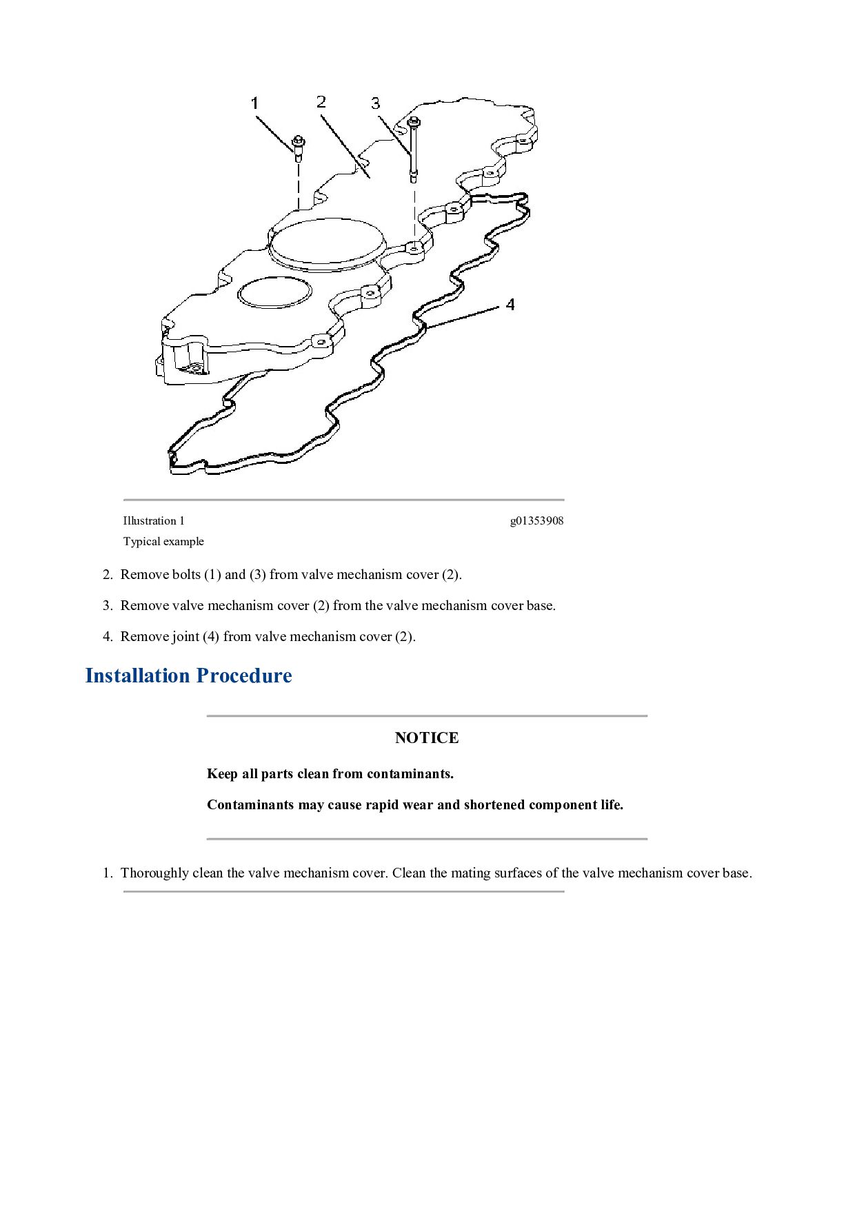
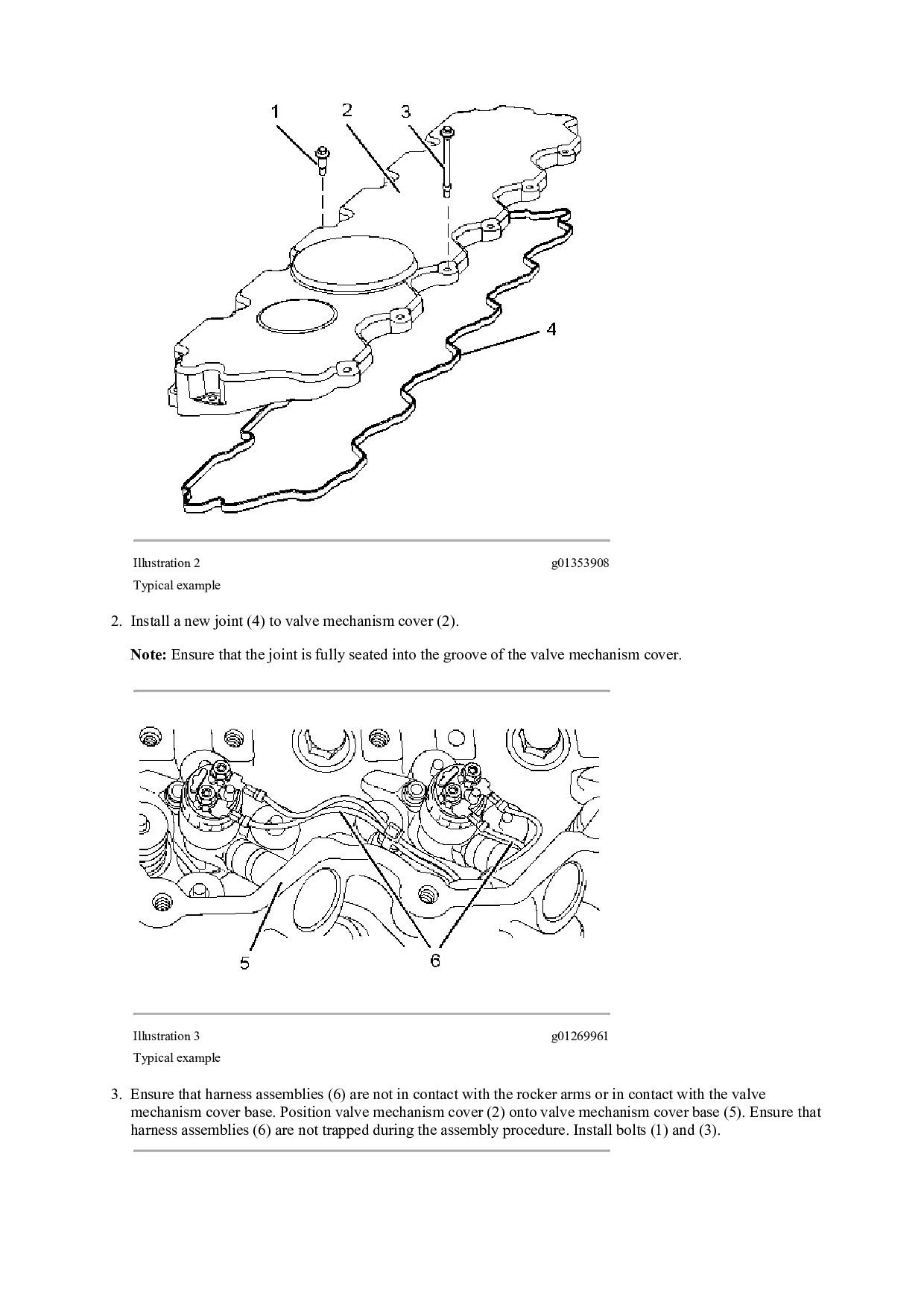
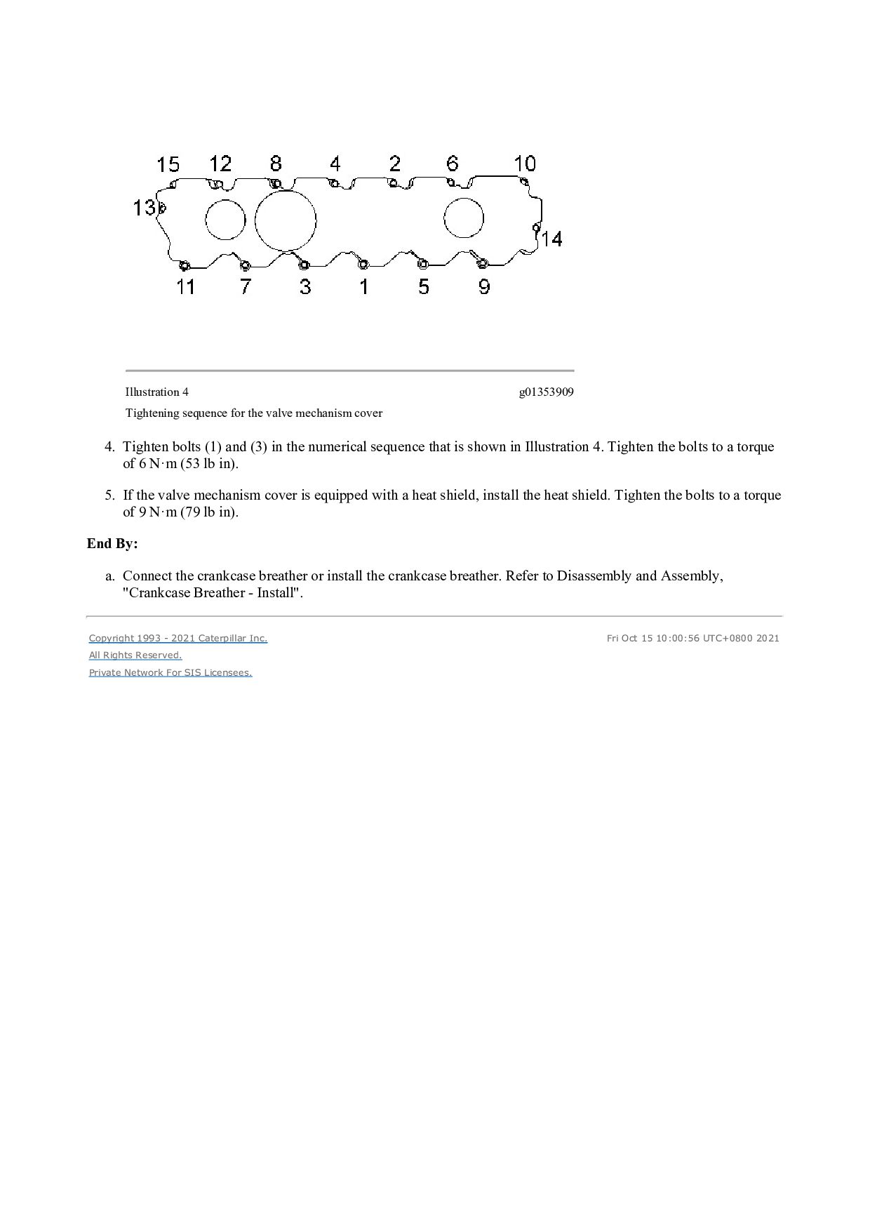
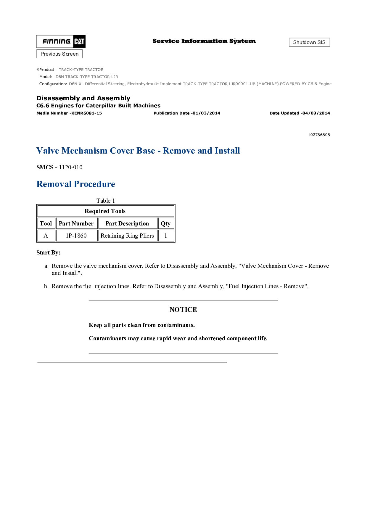
    crankcase breather. Refer to Disassembly and Assembly, "Crankcase Breather - Remove". 2. If the engine is equipped with a cover over the fuel system this will need to be removed. 3. Remove bolts (1) from valve mechanism cover (2). 4. Remove valve mechanism cover (2) from the valve mechanism cover base. 5. Remove joint (3) from valve mechanism cover (2). 6. If necessary, remove the separator for the crankcase breather from the valve mechanism cover base. Refer to Disassembly and Assembly, "Crankcase Breather - Remove". Installation Procedure NOTICE Keep all parts clean from contaminants. Contaminants may cause rapid wear and shortened component life. 1. Thoroughly clean all mating surfaces of the valve mechanism cover. Clean the mating surfaces of the valve mechanism cover base. 2. If necessary, install the separator for the crankcase breather to valve mechanism cover (2). Refer to Disassembly and Assembly, "Crankcase Breather - Install". Illustration 2 g01342429 Typical example 3. Install a new joint (3) to valve mechanism cover (2).
  3. Note: Ensure that the joint is fully seated into the

    groove of the valve mechanism cover. Illustration 3 g01342430 4. Ensure that harness assemblies (5) are not in contact with the rocker arms of the valve mechanism cover base. Position valve mechanism cover (2) onto valve mechanism cover base (4). Ensure that harness assemblies (5) are not trapped during the assembly procedure. Install bolts (1). Illustration 4 g01342431 5. Tighten the bolts in the numerical sequence that is shown in Illustration 4. Tighten the bolts to a torque of 9 N·m (79 lb in). 6. Connect the breather hose to the separator for the crankcase breather. Refer to Disassembly and Assembly, "Crankcase Breather - Install". 7. If the engine is equipped with a cover over the fuel system this will need to be Installed. Copyright 1993 - 2021 Caterpillar Inc. All Rights Reserved. Private Network For SIS Licensees. Fri Oct 15 10:00:00 UTC+0800 2021
  4. Shutdown SIS Previous Screen Product: TRACK-TYPE TRACTOR Model: D6N TRACK-TYPE

    TRACTOR LJR Configuration: D6N XL Differential Steering, Electrohydraulic Implement TRACK-TYPE TRACTOR LJR00001-UP (MACHINE) POWERED BY C6.6 Engine Disassembly and Assembly C6.6 Engines for Caterpillar Built Machines Media Number -KENR6081-15 Publication Date -01/03/2014 Date Updated -04/03/2014 i02786803 Valve Mechanism Cover - Remove and Install - Composite Valve Mechanism Cover SMCS - 1107-010 Removal Procedure Start By: a. Disconnect the crankcase breather or remove the crankcase breather. Refer to Disassembly and Assembly, "Crankcase Breather - Remove". NOTICE Keep all parts clean from contaminants. Contaminants may cause rapid wear and shortened component life. 1. If the valve mechanism cover is equipped with a heat shield, remove the heat shield.
  5. Illustration 1 g01353908 Typical example 2. Remove bolts (1) and

    (3) from valve mechanism cover (2). 3. Remove valve mechanism cover (2) from the valve mechanism cover base. 4. Remove joint (4) from valve mechanism cover (2). Installation Procedure NOTICE Keep all parts clean from contaminants. Contaminants may cause rapid wear and shortened component life. 1. Thoroughly clean the valve mechanism cover. Clean the mating surfaces of the valve mechanism cover base.
  6. https://www.aservicemanualpdf.com/ My Dear Friend! Thank you very much for visiting.

    Full manual if required, please enter the following URL into your browser. https://www.aservicemanualpdf.com/
  7. Illustration 2 g01353908 Typical example 2. Install a new joint

    (4) to valve mechanism cover (2). Note: Ensure that the joint is fully seated into the groove of the valve mechanism cover. Illustration 3 g01269961 Typical example 3. Ensure that harness assemblies (6) are not in contact with the rocker arms or in contact with the valve mechanism cover base. Position valve mechanism cover (2) onto valve mechanism cover base (5). Ensure that harness assemblies (6) are not trapped during the assembly procedure. Install bolts (1) and (3).
  8. Illustration 4 g01353909 Tightening sequence for the valve mechanism cover

    4. Tighten bolts (1) and (3) in the numerical sequence that is shown in Illustration 4. Tighten the bolts to a torque of 6 N·m (53 lb in). 5. If the valve mechanism cover is equipped with a heat shield, install the heat shield. Tighten the bolts to a torque of 9 N·m (79 lb in). End By: a. Connect the crankcase breather or install the crankcase breather. Refer to Disassembly and Assembly, "Crankcase Breather - Install". Copyright 1993 - 2021 Caterpillar Inc. All Rights Reserved. Private Network For SIS Licensees. Fri Oct 15 10:00:56 UTC+0800 2021
  9. Shutdown SIS Previous Screen Product: TRACK-TYPE TRACTOR Model: D6N TRACK-TYPE

    TRACTOR LJR Configuration: D6N XL Differential Steering, Electrohydraulic Implement TRACK-TYPE TRACTOR LJR00001-UP (MACHINE) POWERED BY C6.6 Engine Disassembly and Assembly C6.6 Engines for Caterpillar Built Machines Media Number -KENR6081-15 Publication Date -01/03/2014 Date Updated -04/03/2014 i02786808 Valve Mechanism Cover Base - Remove and Install SMCS - 1120-010 Removal Procedure Table 1 Required Tools Tool Part Number Part Description Qty A 1P-1860 Retaining Ring Pliers 1 Start By: a. Remove the valve mechanism cover. Refer to Disassembly and Assembly, "Valve Mechanism Cover - Remove and Install". b. Remove the fuel injection lines. Refer to Disassembly and Assembly, "Fuel Injection Lines - Remove". NOTICE Keep all parts clean from contaminants. Contaminants may cause rapid wear and shortened component life.
  10. Illustration 1 g01342484 1. Place a temporary identification mark on

    connections (1) for harness assembly (4). 2. Use a deep socket to remove connections (1) from electronic unit injectors (2). 3. If necessary, follow steps 3.a through 3.f in order to remove harness assemblies (4) from valve mechanism cover base (7). a. Cut cable strap (3). b. Disconnect plug (6) from harness assembly (4). c. Use Tooling (A) to remove circlip (5). d. From the outside of valve mechanism cover base (7), push harness assembly (4) inward. Withdraw the harness assembly from valve mechanism cover base (7). e. Remove O-ring seal (8) from harness assembly (4). f. Repeat steps 3.b through 3.e in order to remove the remaining harness assemblies.
  11. Illustration 2 g01342485 Illustration 3 g01342487 4. Loosen isolated screws

    (9) in reverse numerical order. Refer to illustration 3. This will help prevent distortion of valve mechanism cover base (6). 5. Remove valve mechanism cover base (7) from the cylinder head. 6. Remove isolated screws (9) from valve mechanism cover base (7). 7. Remove seal (10) from valve mechanism cover base (7). Installation Procedure Table 2 Required Tools
  12. Tool Part Number Part Description Qty A 1P-1860 Retaining Ring

    Pliers 1 B 1U-6396 O-Ring Assembly Compound 1 C 247-5377 Torque wrench 1 NOTICE Keep all parts clean from contaminants. Contaminants may cause rapid wear and shortened component life. 1. Clean the valve mechanism cover base. Ensure that the mating surfaces are free from damage. Illustration 4 g01342485 2. Install seal (10) to valve mechanism cover base (7). Ensure that seal (10) is seated correctly in the groove in the machined face of valve mechanism cover base (7). 3. Install isolated screws (9) to valve mechanism cover base (6).
  13. Illustration 5 g01342487 4. Position valve mechanism cover base (7)

    on the cylinder head. Tighten isolated screws (9) to a torque of 9 N·m (79 lb in) in the sequence that is shown in illustration 5. Illustration 6 g01342484 5. If necessary, install the harness assemblies for the electronic unit injectors. Follow steps 5.a through 5.h in order to install the harness assemblies for the electronic unit injectors. a. Ensure that harness assembly (4) and the bore in valve mechanism cover base (7) are clean and free from damage. Replace any damaged components. b. Use Tooling (B) to lubricate a new O-ring seal (8). Install the new O-ring seal (8) onto harness assembly (4). c. From the inside of valve mechanism cover base (7), push harness assembly (4) into valve mechanism cover base (7).
  14. d. Use Tooling (A) to install circlip (5). e. Connect

    plug (6) to harness assembly (4). f. Use a deep socket to connect harness (4) to electronic unit injectors (2). Use Tooling (C) to tighten connectors (1) to a torque of 2.4 N·m (21 lb in). g. Install a new cable strap (3) to harness assembly (4). Note: Ensure that cable strap to OE specification. h. Repeat steps 5.a through 5.g for remaining harness assemblies (4). End By: a. Install new fuel injection lines. Refer to Disassembly and Assembly, "Fuel Injection Lines - Install". b. Install the valve mechanism cover. Refer to Disassembly and Assembly, "Valve Mechanism Cover - Remove and Install". Copyright 1993 - 2021 Caterpillar Inc. All Rights Reserved. Private Network For SIS Licensees. Fri Oct 15 10:01:52 UTC+0800 2021
  15. Shutdown SIS Previous Screen Product: TRACK-TYPE TRACTOR Model: D6N TRACK-TYPE

    TRACTOR LJR Configuration: D6N XL Differential Steering, Electrohydraulic Implement TRACK-TYPE TRACTOR LJR00001-UP (MACHINE) POWERED BY C6.6 Engine Disassembly and Assembly C6.6 Engines for Caterpillar Built Machines Media Number -KENR6081-15 Publication Date -01/03/2014 Date Updated -04/03/2014 i05735252 Valve Mechanism Cover Base - Remove and Install - Composite Valve Mechanism Cover Base SMCS - 1120-010 Removal Procedure Table 1 Required Tools Tool Part Number Part Description Qty A 1P-1860 Retaining Ring Pliers 1 Start By: a. Remove the valve mechanism cover. Refer to Disassembly and Assembly, "Valve Mechanism Cover - Remove and Install" for the correct procedure. b. Remove the fuel injection lines. Refer to Disassembly and Assembly, "Fuel Injection Lines - Remove" for the correct procedure. NOTICE Keep all parts clean from contaminants. Contaminants may cause rapid wear and shortened component life. NOTICE Use a deep socket in order to remove the electrical connections from the electronic unit injectors. Use of incorrect tooling will result in damage to the electronic unit injectors.
  16. Illustration 1 g01355167 Typical example 1. Make a temporary identification

    mark on connections (1). 2. Use a deep socket to remove connections (1) from electronic unit injectors (2). 3. Disconnect plugs (7) from harness assemblies (4). 4. If necessary, follow Step 4.a through Step 4.e in order to remove harness assemblies (4) from valve mechanism cover base (6). a. Cut cable strap (3). b. Use Tooling (A) to remove circlip (5). c. From the outside of valve mechanism cover base (6), push harness assembly (4) inward. Withdraw the harness assembly from valve mechanism cover base (6). d. Remove O-ring seal (8) from harness assembly (4). e. Repeat Step 4.a through Step 4.d in order to remove the remaining harness assembly.
  17. Illustration 2 g01354234 Typical example Illustration 3 g01354235 Tightening sequence

    for the valve mechanism cover base 5. Gradually loosen the captive bolts that secure the valve mechanism cover base in reverse numerical order. Refer to Illustration 3. Gradually loosen the captive bolts will help prevent distortion of the valve mechanism cover base. Note: The captive bolts cannot be removed from the valve mechanism cover base. 6. Remove valve mechanism cover base (6) from the cylinder head. 7. Remove seal (9) from valve mechanism cover base (6). Installation Procedure
  18. Table 2 Required Tools Tool Part Number Part Description Qty

    A 1P-1860 Retaining Ring Pliers 1 B 1U-6396 O-Ring Assembly Compound 1 C 247-5377 Torque Wrench 1 D 321-5184 Alignment Pins 2 NOTICE Keep all parts clean from contaminants. Contaminants may cause rapid wear and shortened component life. NOTICE Use a deep socket in order to remove the electrical connections from the electronic unit injectors. Use of incorrect tooling will result in damage to the electronic unit injectors. 1. Clean the valve mechanism cover base. Ensure that the mating surfaces are free from damage. Illustration 4 g01354234 Typical example
  19. 2. Install seal (9) to valve mechanism cover base (6).

    Ensure that the seal is seated correctly in the groove in the valve mechanism cover base. Illustration 5 g01354235 Tightening sequence for the valve mechanism cover base Illustration 6 g01419953 3. Position valve mechanism cover base (6) onto the cylinder head. Install Tooling (D) in Positions (X) in order to align the valve mechanism cover base. 4. Gradually tighten the captive bolts that secure the valve mechanism cover base to a torque of 9 N·m (79 lb in) in the sequence that is shown in Illustration 5. 5. Remove the Tooling (D) from Positions (X).
  20. Illustration 7 g01355167 Typical example 6. If necessary, install the

    harness assemblies for the electronic unit injectors. Follow Step 6.a through Step 6.e in order to install the harness assemblies to the electronic unit injectors. a. Ensure that harness assembly (4) and the bore in valve mechanism cover base (6) are clean and free from damage. Replace any damaged components. b. Use Tooling (B) to lubricate a new O-ring seal (8). Install O-ring seal (8) onto harness assembly (4). c. From the inside of valve mechanism cover base (6), push harness assembly (4) into the valve mechanism cover base. d. Use Tooling (A) to install circlip (5). e. Repeat Step 6.a through Step 8 for the remaining harness assembly. 7. Use a deep socket to connect harness (4) to electronic unit injectors (2). Use Tooling (C) to tighten connectors (1) to a torque of 2.4 N·m (21 lb in). 8. If necessary, install new cable straps (3) to harness assemblies (4). Note: Ensure that cable straps are to Original Equipment manufacture (OEM) specification. 9. Connect plugs (7) to harness assemblies (4). End By: a. Install new fuel injection lines. Refer to Disassembly and Assembly, "Fuel Injection Lines - Install" for the correct procedure. b. Install the valve mechanism cover. Refer to Disassembly and Assembly, "Valve Mechanism Cover - Remove and Install" for the correct procedure. Copyright 1993 - 2021 Caterpillar Inc. All Rights Reserved. Fri Oct 15 10:02:48 UTC+0800 2021
  21. Shutdown SIS Previous Screen Product: TRACK-TYPE TRACTOR Model: D6N TRACK-TYPE

    TRACTOR LJR Configuration: D6N XL Differential Steering, Electrohydraulic Implement TRACK-TYPE TRACTOR LJR00001-UP (MACHINE) POWERED BY C6.6 Engine Disassembly and Assembly C6.6 Engines for Caterpillar Built Machines Media Number -KENR6081-15 Publication Date -01/03/2014 Date Updated -04/03/2014 i02786810 Rocker Shaft and Pushrod - Remove SMCS - 1102-011; 1208-011 Removal Procedure Table 1 Required Tools Tool Part Number Part Description Qty A 227-4389 E10 Torx Socket 1 Start By: a. Remove the valve mechanism cover. Refer to Disassembly and Assembly, "Valve Mechanism Cover - Remove and Install". NOTICE Keep all parts clean from contaminants. Contaminants may cause rapid wear and shortened component life. Illustration 1 g01340040
  22. Illustration 2 g01340041 1. Use Tooling (A) to progressively loosen

    torx screws (1). Begin at the ends of the rocker shaft assembly and work toward the center. Note: To avoid distortion of rocker shaft assembly (2), each torx screw should be loosened by half a turn at one time. Repeat the procedure until all torx screws are loosened. 2. Remove torx screws (1) from rocker shaft assembly (2). 3. Remove rocker shaft assembly (2) from the cylinder head. 4. Place an identification mark on pushrods (3) in order to show the location. Remove the pushrods from the cylinder head. Note: Identification will ensure that the pushrods can be reinstalled in the original positions. Do not interchange the positions of used pushrods. 5. Make a temporary mark on valve bridges (4) in order to show the location and the orientation. Remove the valve bridges from the cylinder head. Note: Identification will ensure that the valve bridges can be reinstalled in the original location and the original orientation. Do not interchange the location or the orientation of used valve bridges. Copyright 1993 - 2021 Caterpillar Inc. All Rights Reserved. Private Network For SIS Licensees. Fri Oct 15 10:03:43 UTC+0800 2021
  23. Shutdown SIS Previous Screen Product: TRACK-TYPE TRACTOR Model: D6N TRACK-TYPE

    TRACTOR LJR Configuration: D6N XL Differential Steering, Electrohydraulic Implement TRACK-TYPE TRACTOR LJR00001-UP (MACHINE) POWERED BY C6.6 Engine Disassembly and Assembly C6.6 Engines for Caterpillar Built Machines Media Number -KENR6081-15 Publication Date -01/03/2014 Date Updated -04/03/2014 i02786815 Rocker Shaft - Disassemble SMCS - 1102-015 Disassembly Procedure Start By: a. Remove the rocker shaft assembly. Refer to Disassembly and Assembly, "Rocker Shaft and Pushrod - Remove". NOTICE Keep all parts clean from contaminants. Contaminants may cause rapid wear and shortened component life. Personal injury can result from being struck by parts propelled by a released spring force. Make sure to wear all necessary protective equipment. Follow the recommended procedure and use all recommended tooling to release the spring force. 1. Make an identification mark on each rocker arm assembly in order to show the location. Note: The components must be reinstalled in the original location. Do not interchange components.
  24. Illustration 1 g01417114 2. Remove pedestals (1) from rocker shaft

    (5). It is not necessary to remove locators (2) from the pedestals. 3. Remove rocker arm assembly (4) for the exhaust valve from rocker shaft (5). Remove rocker arm assembly (3) for the inlet valve from rocker shaft (5). Begin at the rear of the rocker shaft assembly. Note: The rocker arm assembly for the inlet valve is longer than the rocker arm assembly for the exhaust valve. 4. Remove spring (6) from rocker shaft (5). 5. Repeat Steps 3 and 4 in order to remove the remaining rocker arms from rocker shaft (5).
  25. Illustration 2 g01340048 6. If necessary, remove retaining clip (7)

    and remove spring (8) from the front end of rocker shaft (5). 7. If necessary, remove nuts (10) and adjusters (9) from the rocker arms. Make a temporary identification mark on each adjuster in order to show the location. Note: The components must be reinstalled in the original location. Do not interchange components. Copyright 1993 - 2021 Caterpillar Inc. All Rights Reserved. Private Network For SIS Licensees. Fri Oct 15 10:04:39 UTC+0800 2021
  26. Shutdown SIS Previous Screen Product: TRACK-TYPE TRACTOR Model: D6N TRACK-TYPE

    TRACTOR LJR Configuration: D6N XL Differential Steering, Electrohydraulic Implement TRACK-TYPE TRACTOR LJR00001-UP (MACHINE) POWERED BY C6.6 Engine Disassembly and Assembly C6.6 Engines for Caterpillar Built Machines Media Number -KENR6081-15 Publication Date -01/03/2014 Date Updated -04/03/2014 i02786828 Rocker Shaft - Assemble SMCS - 1102-016 Assembly Procedure NOTICE Keep all parts clean from contaminants. Contaminants may cause rapid wear and shortened component life. 1. Ensure that all components are clean and free from wear or damage. Refer to Specifications, "Rocker Shaft" for more information. If necessary, replace any components that are worn or damaged.
  27. Please write to us. Our email: [email protected] Please go to

    the homepage to get the full manual, or other brand PDF manuals. Home Site: aservicemanualpdf.com
  28. Thank you very much for your reading. Please Click Here.

    Then Get COMPLETE MANUAL. NO WAITING NOTE: If there is no response to click on the link above, please download the PDF document first and then click on it.
  29. Illustration 1 g01417114 2. If necessary, install nuts (10) and

    adjusters (9) to rocker arm assemblies (3) and (4). If the original adjusters are reused, ensure that the adjusters are installed in the original positions. Illustration 2 g01340048
  30. 3. Install retaining clip (7) and spring (8) to the

    front end of rocker shaft (5). 4. Lubricate the bores of rocker arm assemblies (3) and (4) and rocker shaft (5) with clean engine oil. 5. Install rocker arm assembly (3) for number 1 inlet valve to the rocker shaft. Install rocker arm assembly (4) for number 1 exhaust valve to rocker shaft (5). Note: The rocker arm assembly for the inlet valve is longer than the rocker arm assembly for the exhaust valve. Used components should be installed in the original location. 6. If necessary, ensure that locator (2) is correctly seated in pedestal (1). Ensure that the counterbores for the holes in rocker shaft (5) are upward. Align locator (2) with the hole to the front of rocker shaft (5). Install the pedestal to the rocker shaft. Improper assembly of parts that are spring loaded can cause bodily injury. To prevent possible injury, follow the established assembly procedure and wear protective equipment. 7. Install spring (6) to rocker shaft (5). 8. Repeat Steps 5 to 7 in order to assemble the remaining components to rocker shaft (5). End By: a. Install the rocker shaft assembly. Refer to Disassembly and Assembly, "Rocker Shaft and Pushrod - Install". Copyright 1993 - 2021 Caterpillar Inc. All Rights Reserved. Private Network For SIS Licensees. Fri Oct 15 10:05:35 UTC+0800 2021
  31. Shutdown SIS Previous Screen Product: TRACK-TYPE TRACTOR Model: D6N TRACK-TYPE

    TRACTOR LJR Configuration: D6N XL Differential Steering, Electrohydraulic Implement TRACK-TYPE TRACTOR LJR00001-UP (MACHINE) POWERED BY C6.6 Engine Disassembly and Assembly C6.6 Engines for Caterpillar Built Machines Media Number -KENR6081-15 Publication Date -01/03/2014 Date Updated -04/03/2014 i03547100 Rocker Shaft and Pushrod - Install SMCS - 1102-012; 1208-012 Installation Procedure Table 1 Required Tools Tool Part Number Part Description Qty A 227-4389 E10 Torx Socket 1 B 385-4005 Feeler Gauge 1 NOTICE Keep all parts clean from contaminants. Contaminants may cause rapid wear and shortened component life. 1. Clean the valve bridges. Inspect the valve bridges for wear or damage. Replace any valve bridges that are worn or damaged.
  32. https://www.aservicemanualpdf.com/ My Dear Friend! Thank you very much for visiting.

    Full manual if required, please enter the following URL into your browser. https://www.aservicemanualpdf.com/