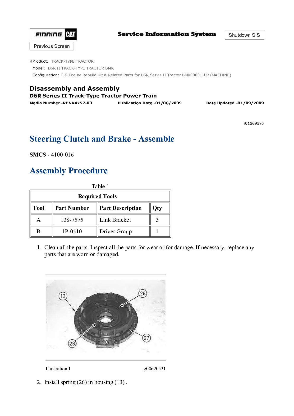
TRACK-TYPE TRACTOR BMK Configuration: C-9 Engine Rebuild Kit & Related Parts for D6R Series II Tractor BMK00001-UP (MACHINE) Disassembly and Assembly D6R Series II Track-Type Tractor Power Train Media Number -RENR4257-03 Publication Date -01/08/2009 Date Updated -01/09/2009 i01569580 Steering Clutch and Brake - Assemble SMCS - 4100-016 Assembly Procedure Table 1 Required Tools Tool Part Number Part Description Qty A 138-7575 Link Bracket 3 B 1P-0510 Driver Group 1 1. Clean all the parts. Inspect all the parts for wear or for damage. If necessary, replace any parts that are worn or damaged. Illustration 1 g00620531 2. Install spring (26) in housing (13) .
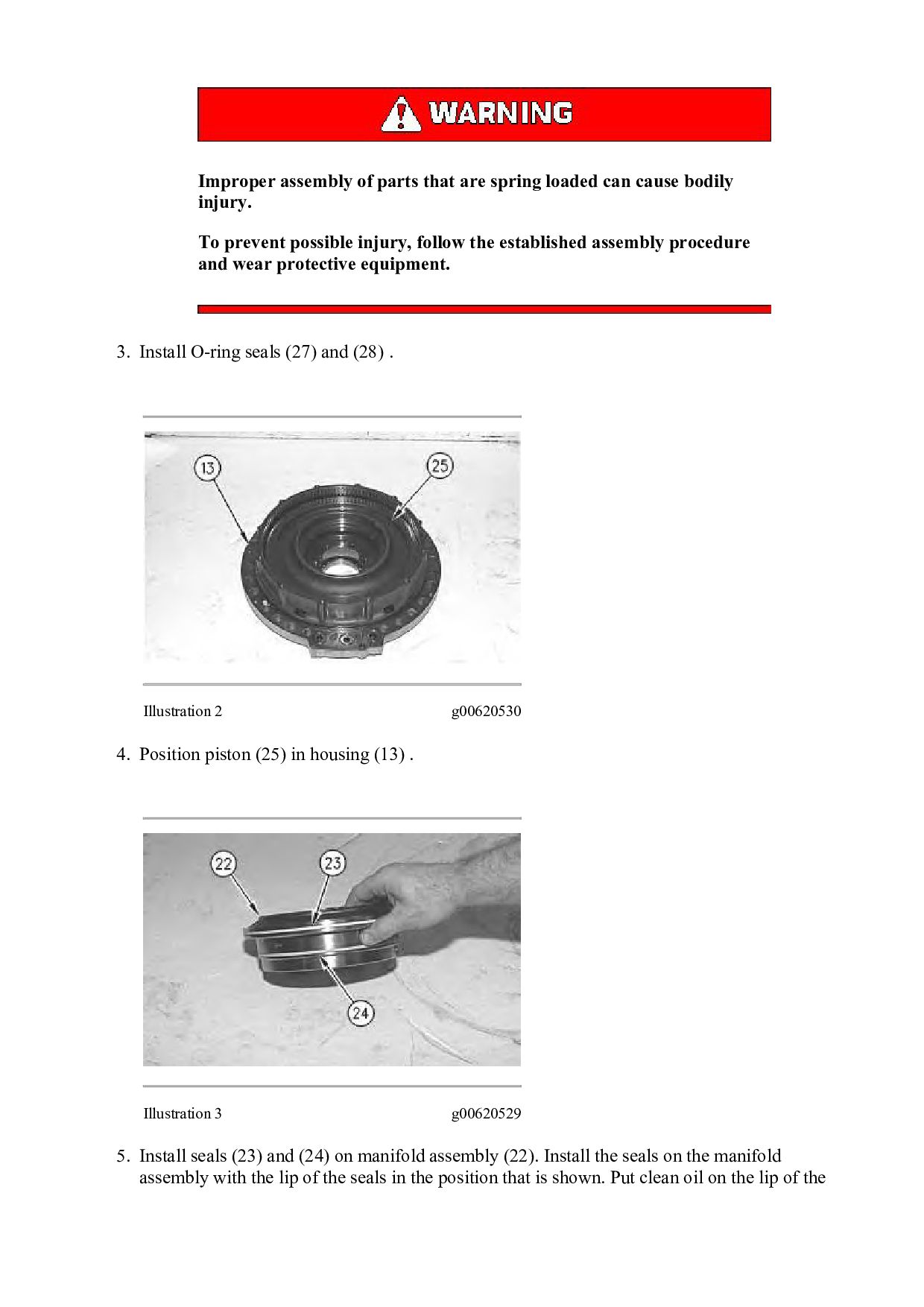
bodily injury. To prevent possible injury, follow the established assembly procedure and wear protective equipment. 3. Install O-ring seals (27) and (28) . Illustration 2 g00620530 4. Position piston (25) in housing (13) . Illustration 3 g00620529 5. Install seals (23) and (24) on manifold assembly (22). Install the seals on the manifold assembly with the lip of the seals in the position that is shown. Put clean oil on the lip of the
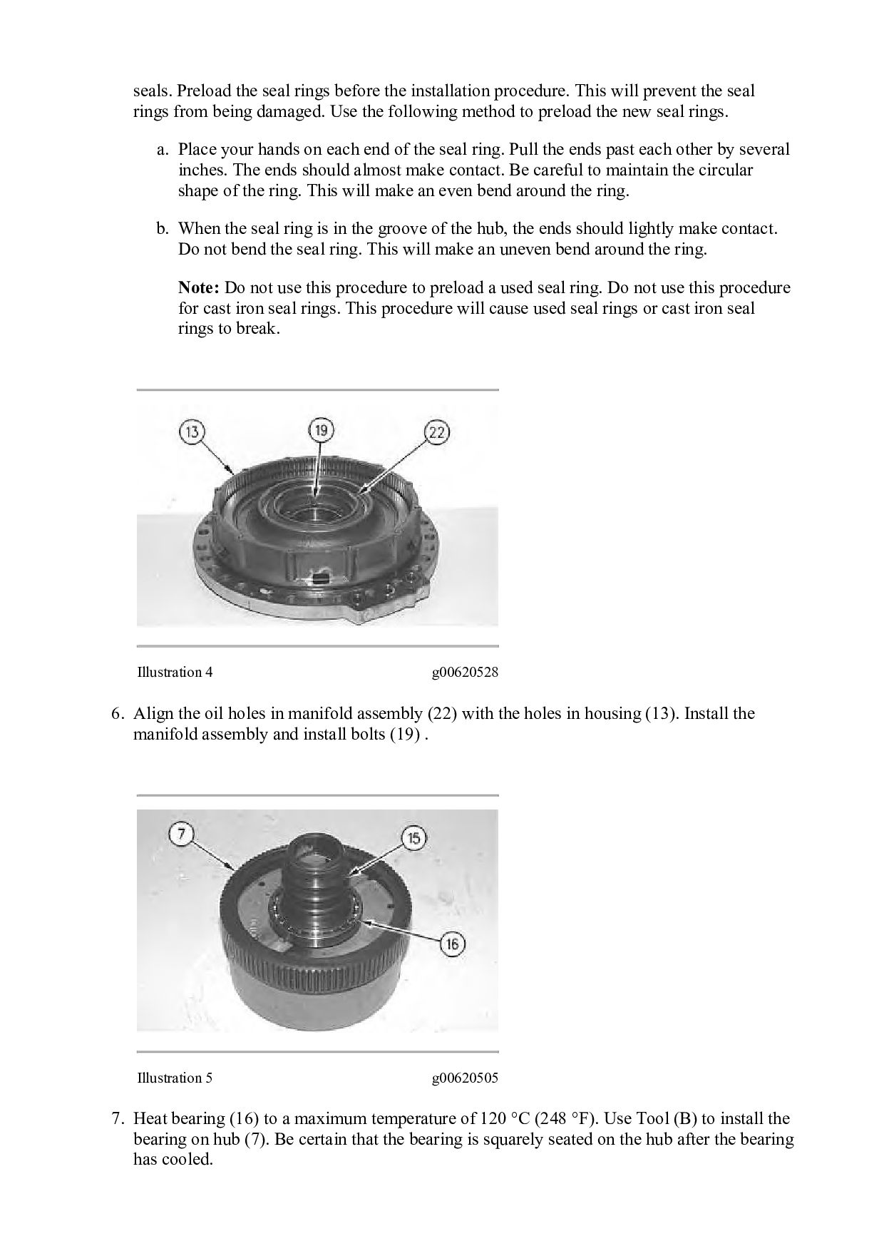
will prevent the seal rings from being damaged. Use the following method to preload the new seal rings. a. Place your hands on each end of the seal ring. Pull the ends past each other by several inches. The ends should almost make contact. Be careful to maintain the circular shape of the ring. This will make an even bend around the ring. b. When the seal ring is in the groove of the hub, the ends should lightly make contact. Do not bend the seal ring. This will make an uneven bend around the ring. Note: Do not use this procedure to preload a used seal ring. Do not use this procedure for cast iron seal rings. This procedure will cause used seal rings or cast iron seal rings to break. Illustration 4 g00620528 6. Align the oil holes in manifold assembly (22) with the holes in housing (13). Install the manifold assembly and install bolts (19) . Illustration 5 g00620505 7. Heat bearing (16) to a maximum temperature of 120 °C (248 °F). Use Tool (B) to install the bearing on hub (7). Be certain that the bearing is squarely seated on the hub after the bearing has cooled.
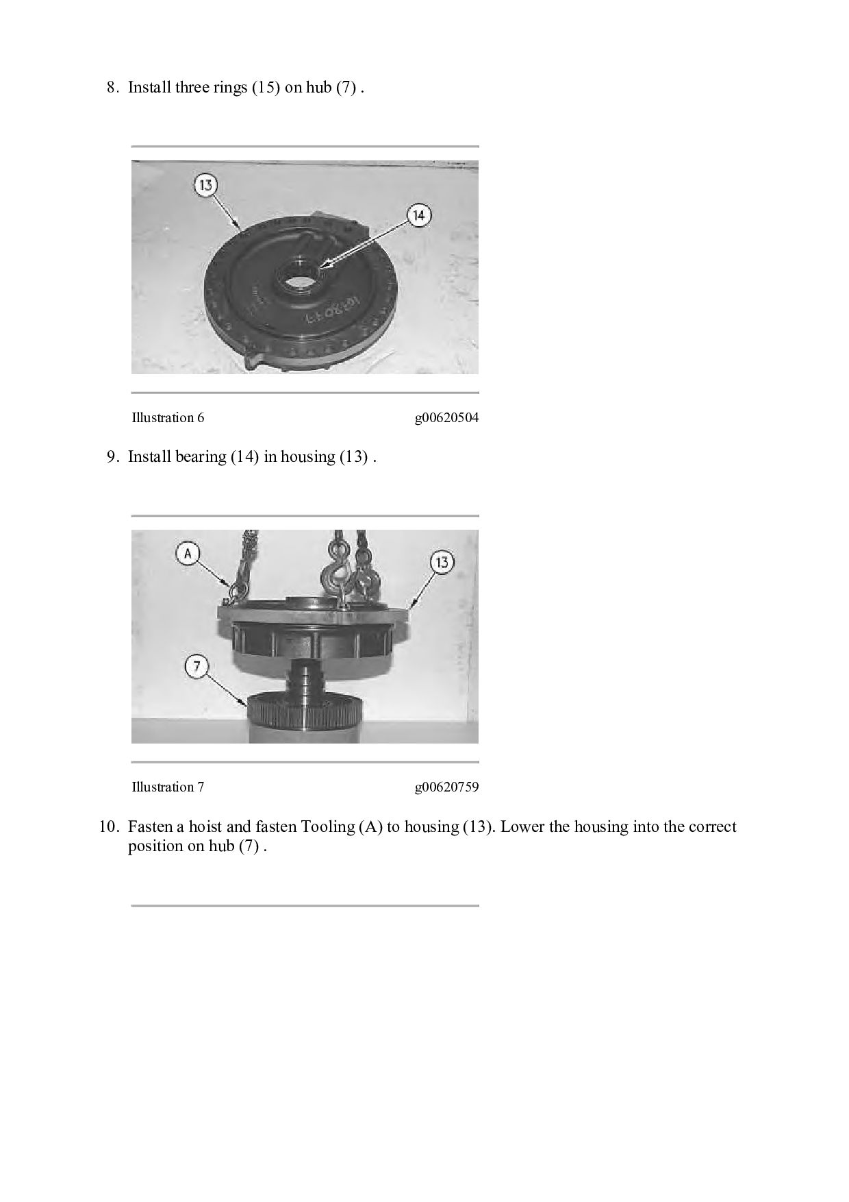
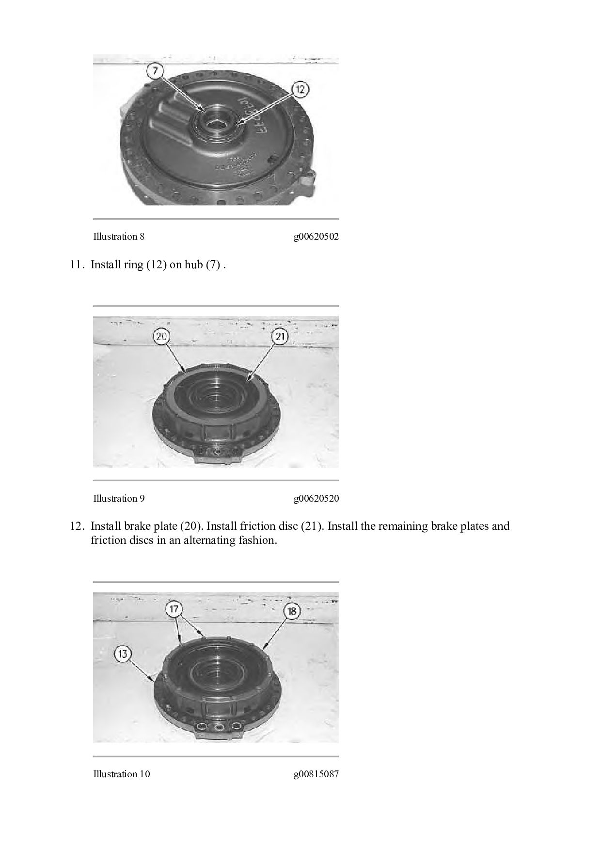
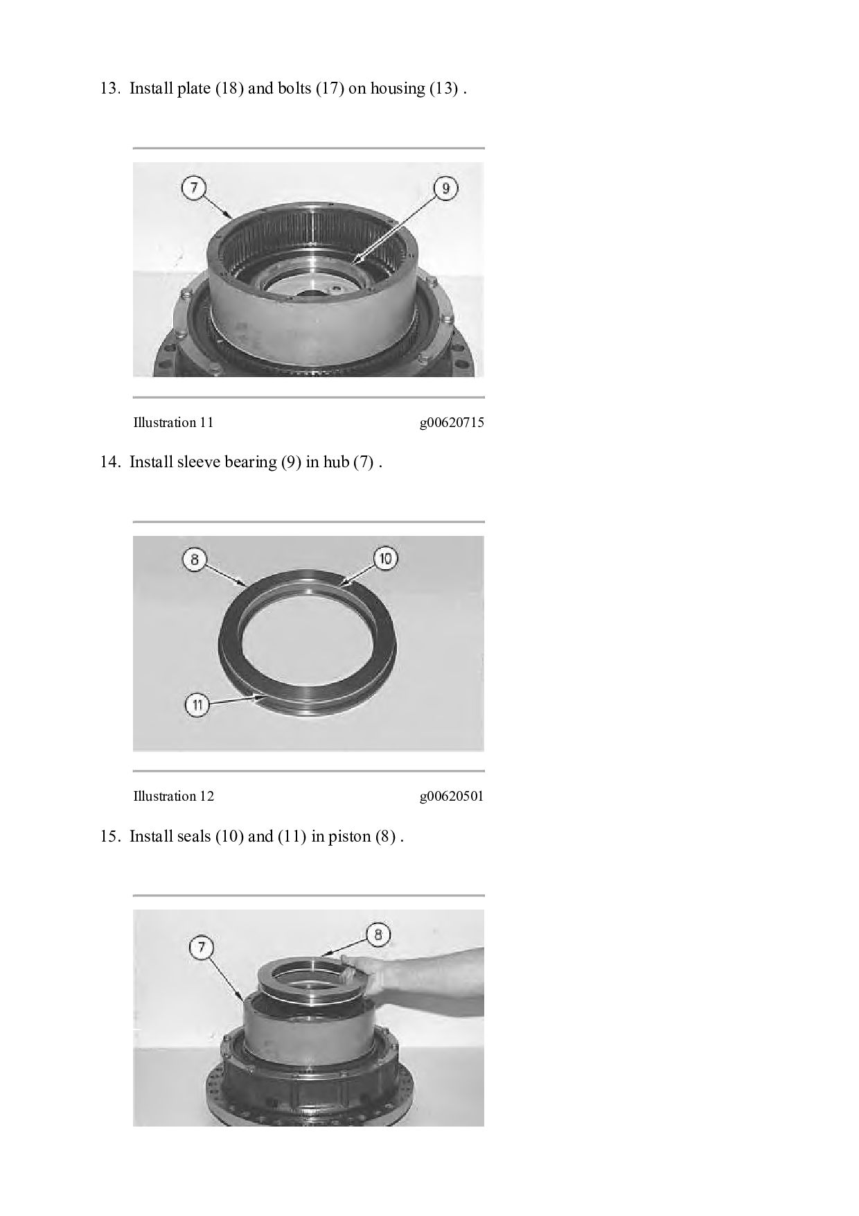
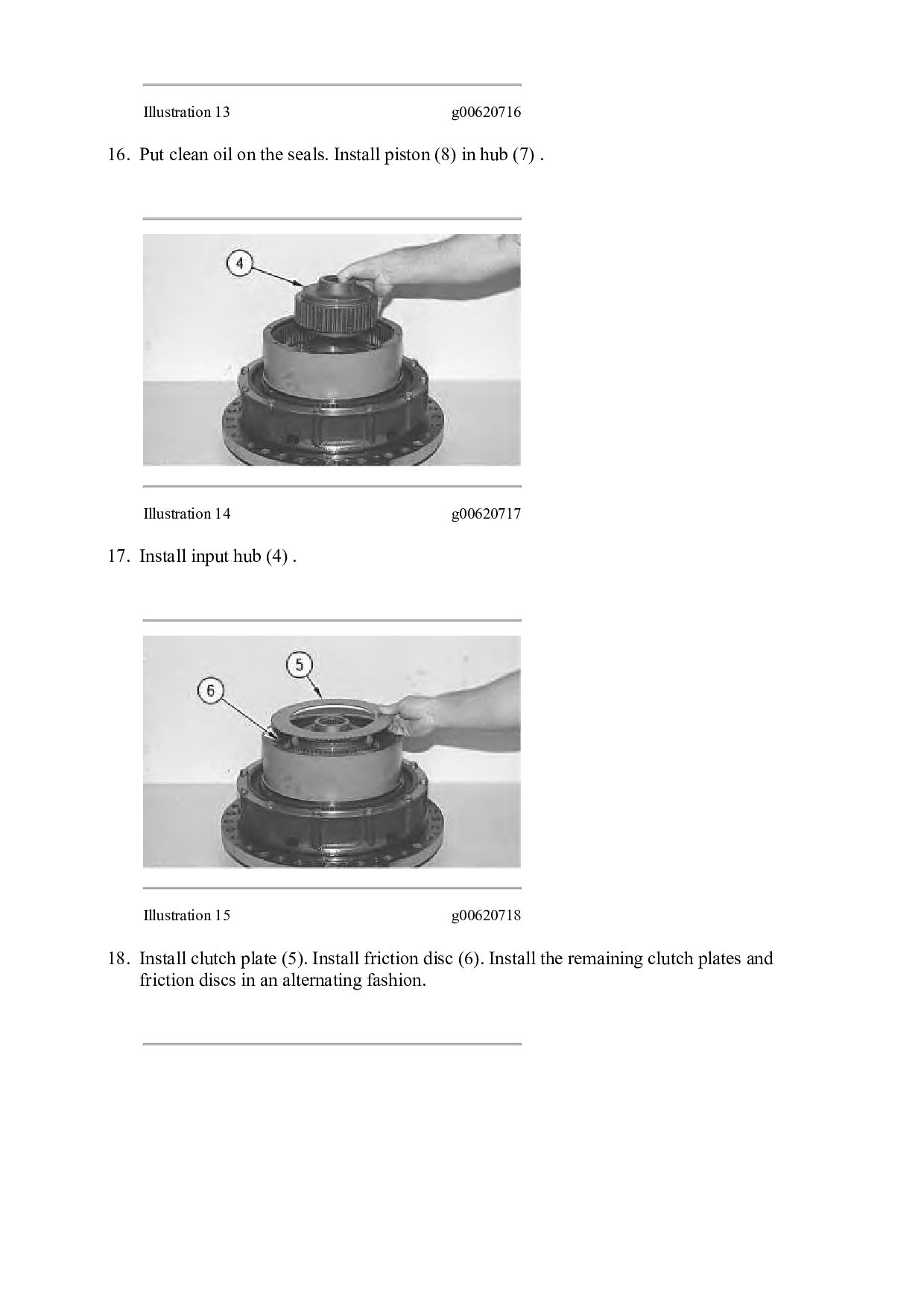
6 g00620504 9. Install bearing (14) in housing (13) . Illustration 7 g00620759 10. Fasten a hoist and fasten Tooling (A) to housing (13). Lower the housing into the correct position on hub (7) .
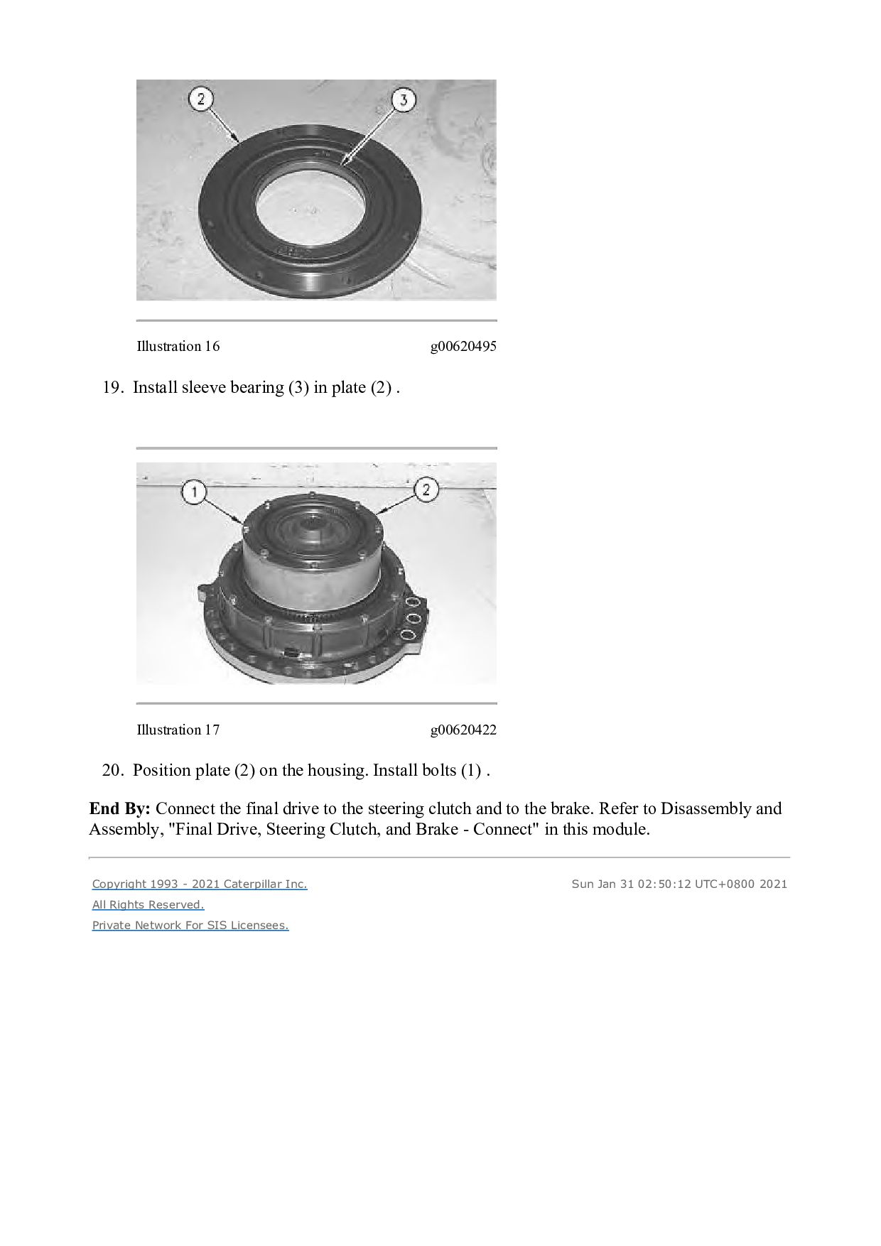
(2) . Illustration 17 g00620422 20. Position plate (2) on the housing. Install bolts (1) . End By: Connect the final drive to the steering clutch and to the brake. Refer to Disassembly and Assembly, "Final Drive, Steering Clutch, and Brake - Connect" in this module. Copyright 1993 - 2021 Caterpillar Inc. All Rights Reserved. Private Network For SIS Licensees. Sun Jan 31 02:50:12 UTC+0800 2021
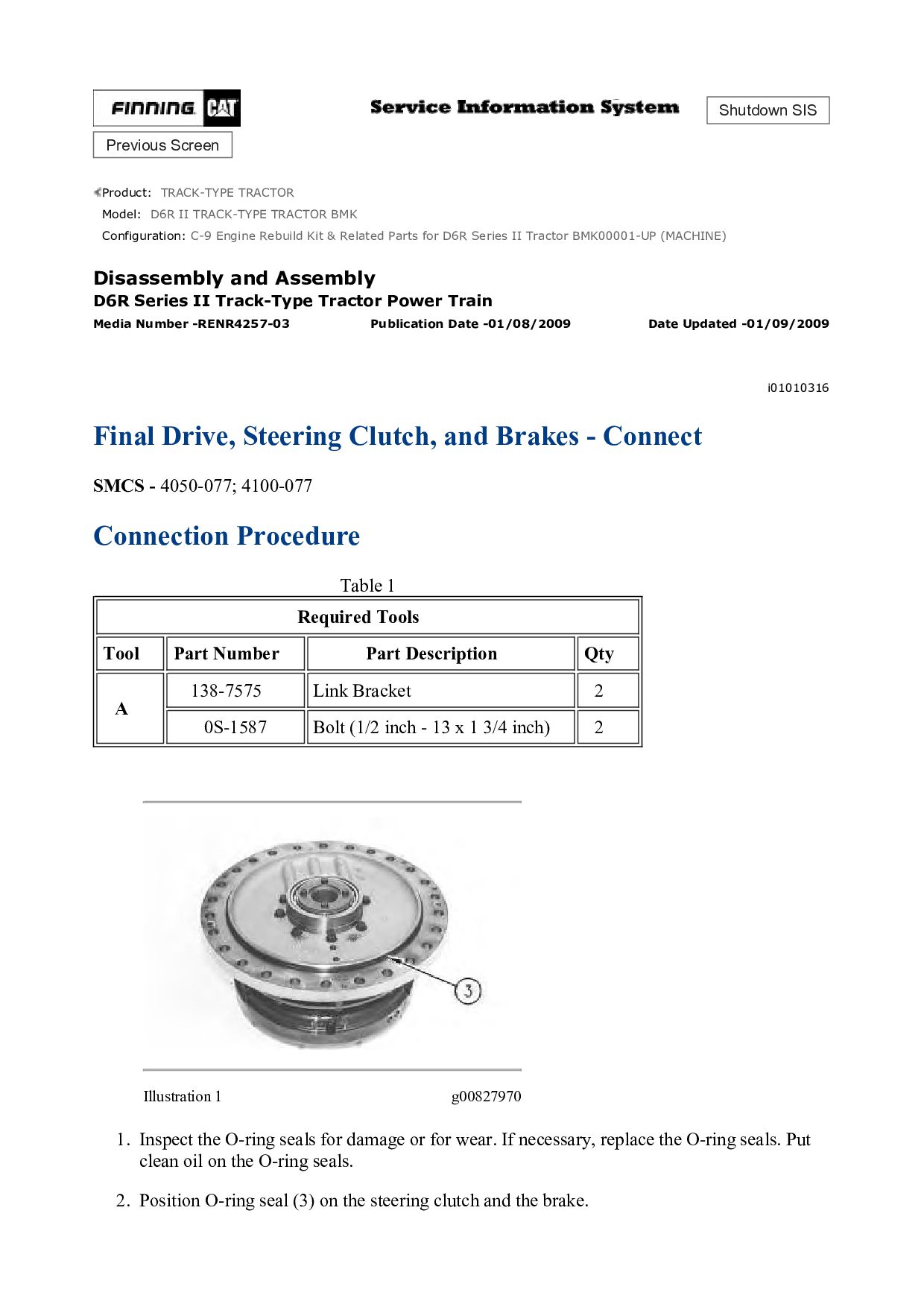
TRACK-TYPE TRACTOR BMK Configuration: C-9 Engine Rebuild Kit & Related Parts for D6R Series II Tractor BMK00001-UP (MACHINE) Disassembly and Assembly D6R Series II Track-Type Tractor Power Train Media Number -RENR4257-03 Publication Date -01/08/2009 Date Updated -01/09/2009 i01010316 Final Drive, Steering Clutch, and Brakes - Connect SMCS - 4050-077; 4100-077 Connection Procedure Table 1 Required Tools Tool Part Number Part Description Qty A 138-7575 Link Bracket 2 0S-1587 Bolt (1/2 inch - 13 x 1 3/4 inch) 2 Illustration 1 g00827970 1. Inspect the O-ring seals for damage or for wear. If necessary, replace the O-ring seals. Put clean oil on the O-ring seals. 2. Position O-ring seal (3) on the steering clutch and the brake.
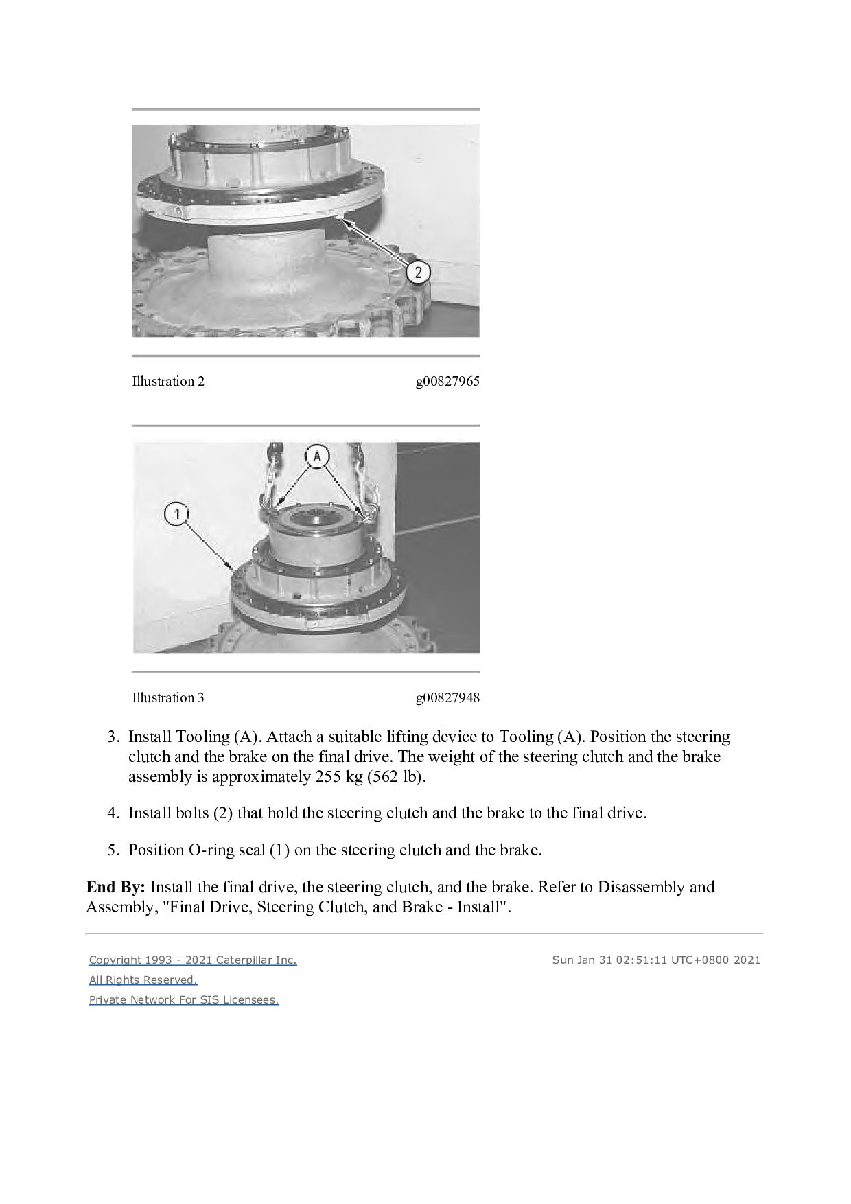
Attach a suitable lifting device to Tooling (A). Position the steering clutch and the brake on the final drive. The weight of the steering clutch and the brake assembly is approximately 255 kg (562 lb). 4. Install bolts (2) that hold the steering clutch and the brake to the final drive. 5. Position O-ring seal (1) on the steering clutch and the brake. End By: Install the final drive, the steering clutch, and the brake. Refer to Disassembly and Assembly, "Final Drive, Steering Clutch, and Brake - Install". Copyright 1993 - 2021 Caterpillar Inc. All Rights Reserved. Private Network For SIS Licensees. Sun Jan 31 02:51:11 UTC+0800 2021
TRACK-TYPE TRACTOR BMK Configuration: C-9 Engine Rebuild Kit & Related Parts for D6R Series II Tractor BMK00001-UP (MACHINE) Disassembly and Assembly D6R Series II Track-Type Tractor Power Train Media Number -RENR4257-03 Publication Date -01/08/2009 Date Updated -01/09/2009 i01676030 Final Drive, Steering Clutch and Brake - Install SMCS - 4050-012; 4100-012 Installation Procedure Table 1 Required Tools Tool Part Number Part Description Qty A 8T-3207 Lifting Bracket 1 5P-8622 Shackle 1 1D-4615 Bolt (3/4 inch by 10 by 5 1/2 inch) 2 1B-4331 Nut (3/4 inch by 10) 2 5P-8248 Washer 4 Without the sun gear in place, the brakes are ineffective. Personal injury or death could result. Provide other means to hold or stop the machine.
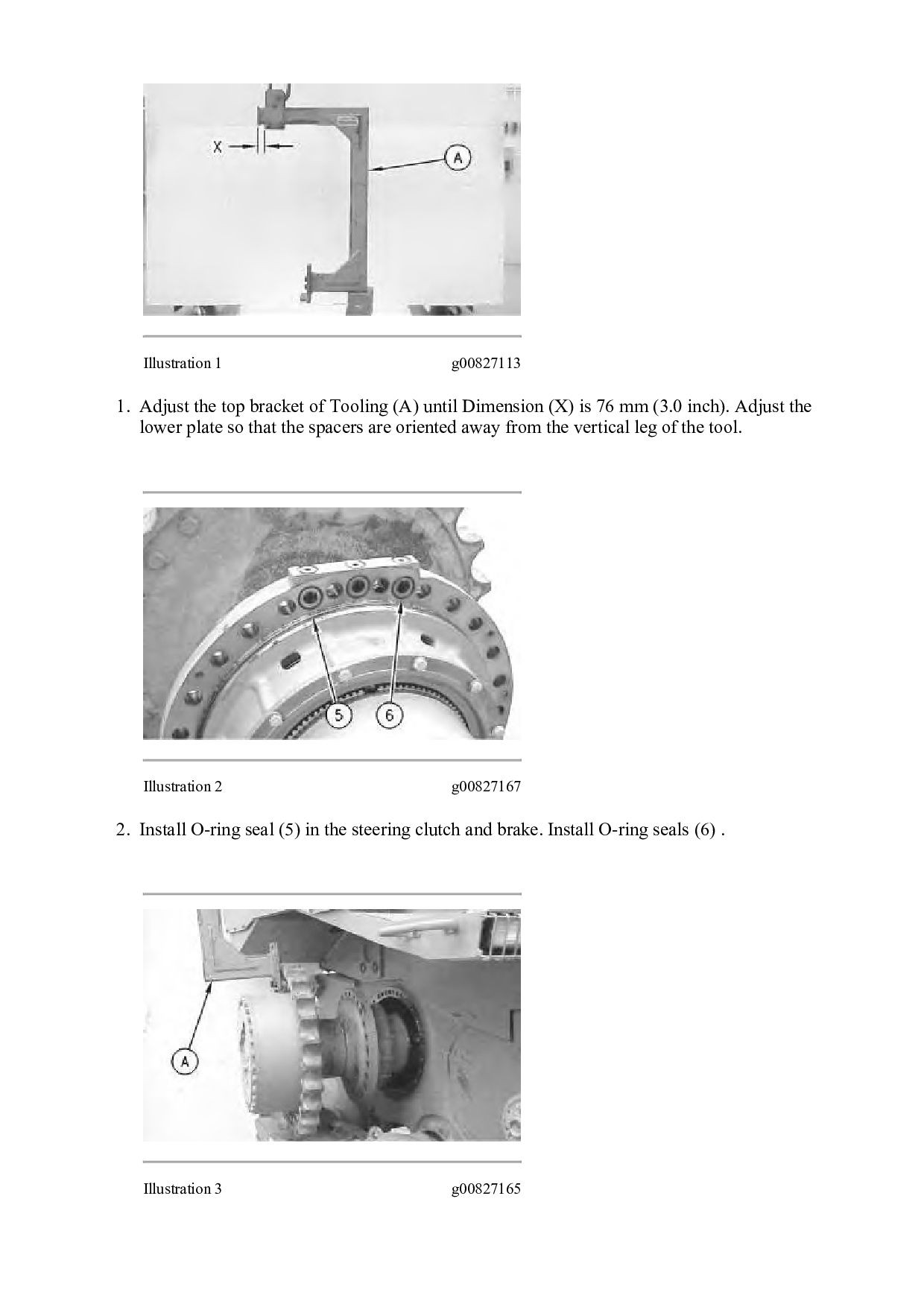
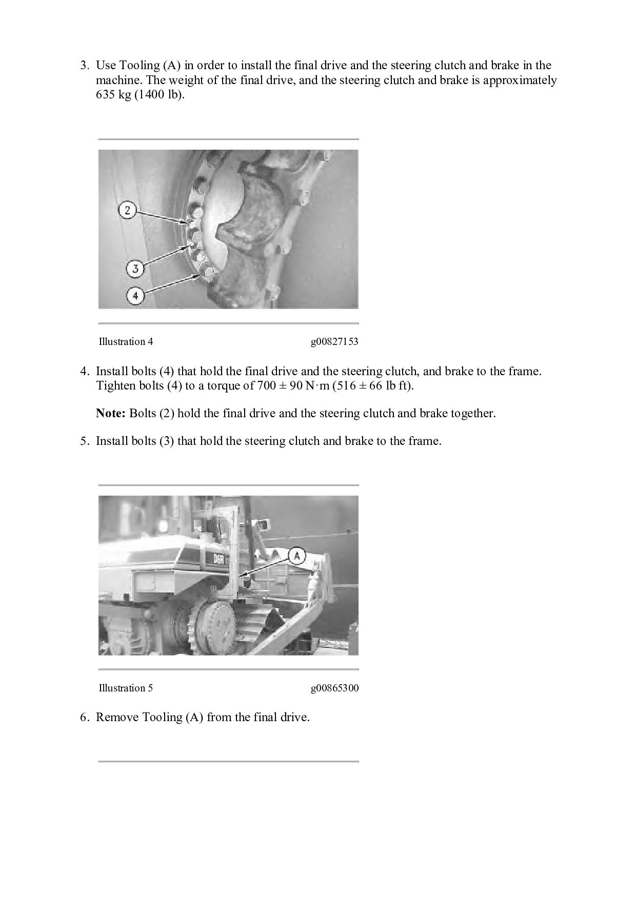
(A) until Dimension (X) is 76 mm (3.0 inch). Adjust the lower plate so that the spacers are oriented away from the vertical leg of the tool. Illustration 2 g00827167 2. Install O-ring seal (5) in the steering clutch and brake. Install O-ring seals (6) . Illustration 3 g00827165
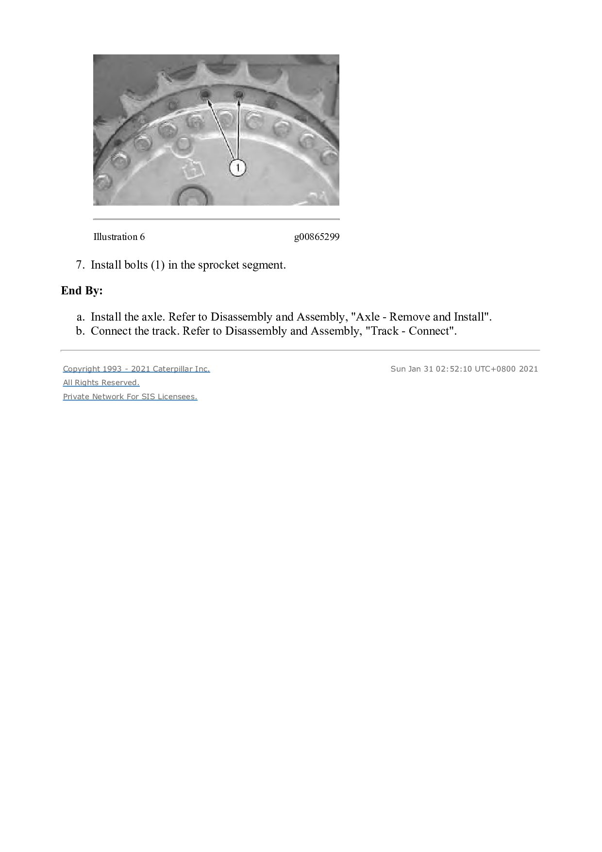
drive and the steering clutch and brake in the machine. The weight of the final drive, and the steering clutch and brake is approximately 635 kg (1400 lb). Illustration 4 g00827153 4. Install bolts (4) that hold the final drive and the steering clutch, and brake to the frame. Tighten bolts (4) to a torque of 700 ± 90 N·m (516 ± 66 lb ft). Note: Bolts (2) hold the final drive and the steering clutch and brake together. 5. Install bolts (3) that hold the steering clutch and brake to the frame. Illustration 5 g00865300 6. Remove Tooling (A) from the final drive.
segment. End By: a. Install the axle. Refer to Disassembly and Assembly, "Axle - Remove and Install". b. Connect the track. Refer to Disassembly and Assembly, "Track - Connect". Copyright 1993 - 2021 Caterpillar Inc. All Rights Reserved. Private Network For SIS Licensees. Sun Jan 31 02:52:10 UTC+0800 2021
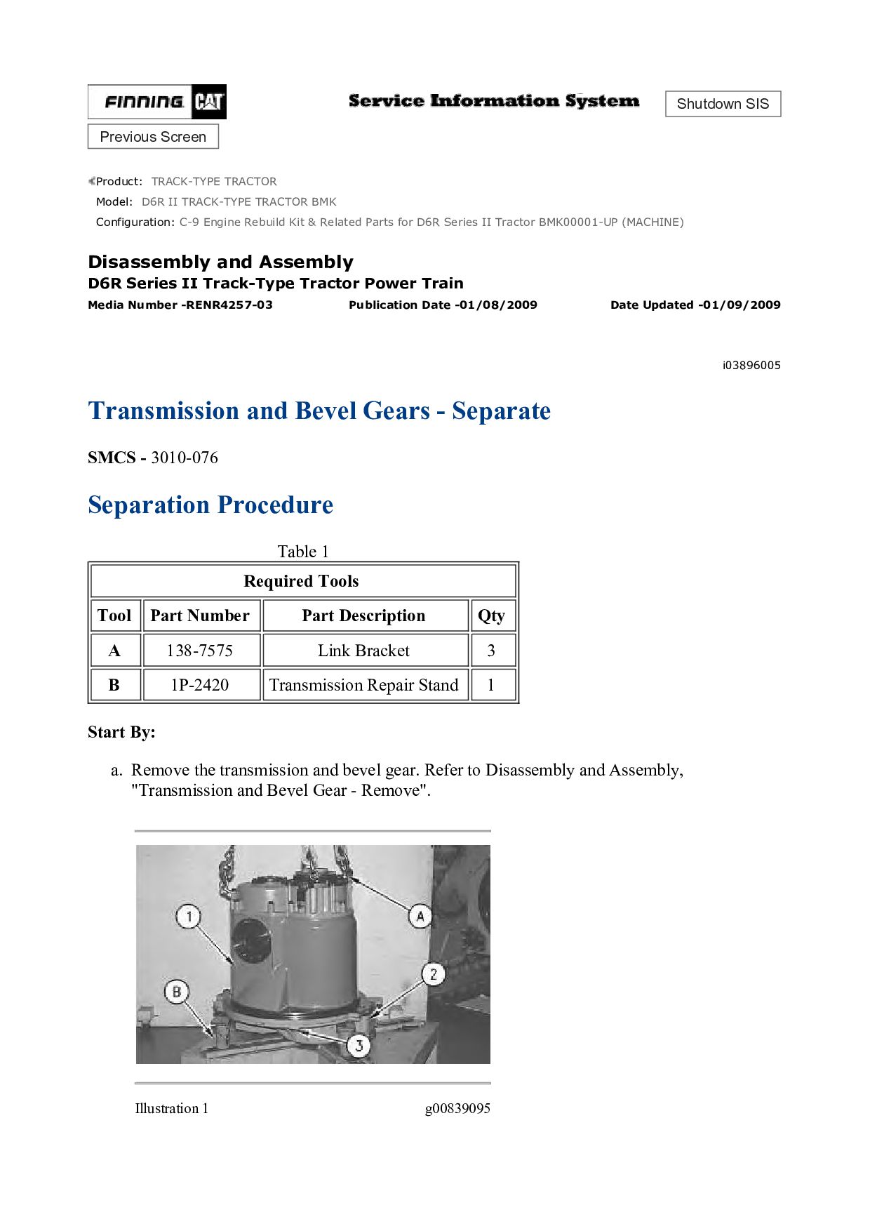
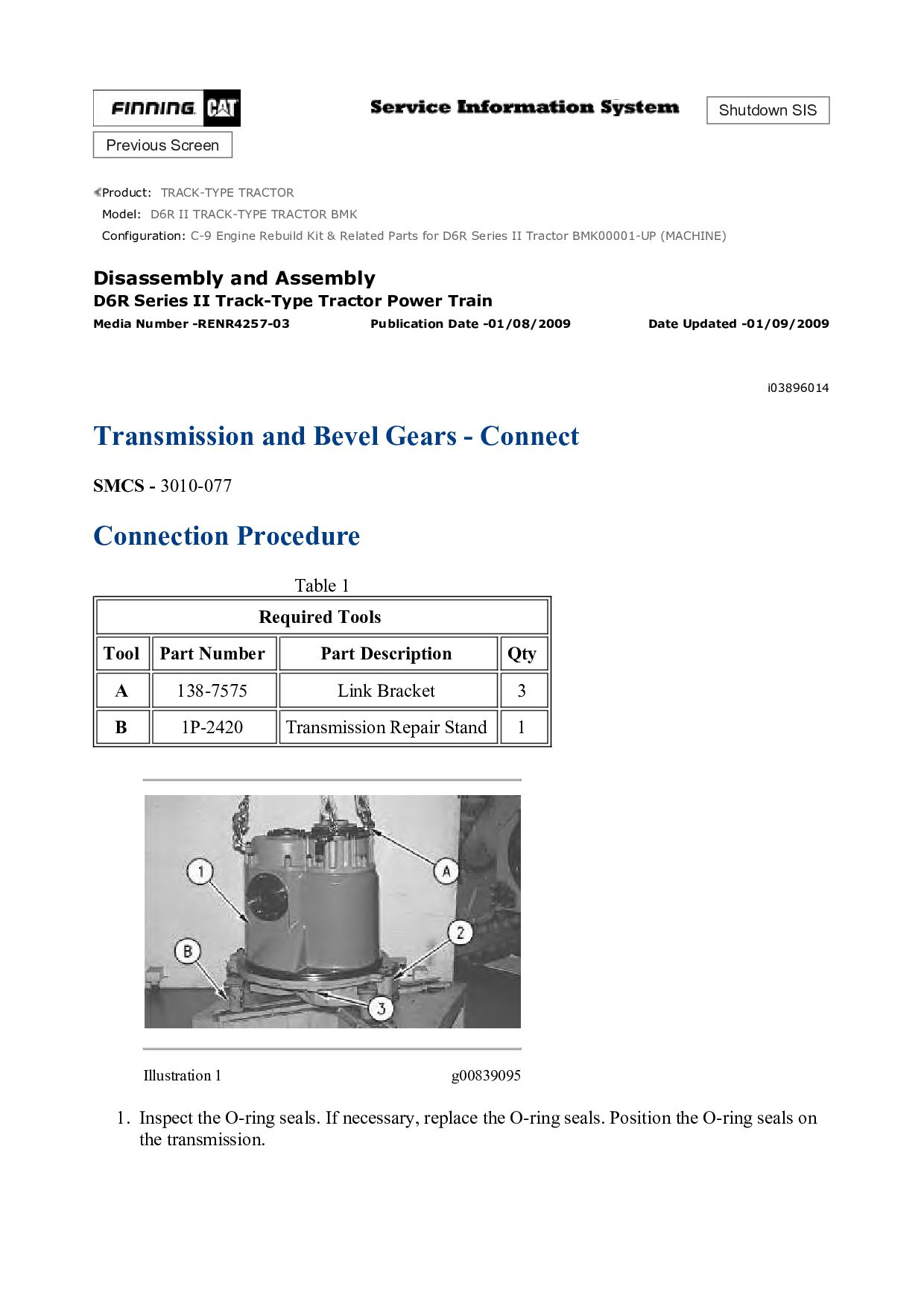
TRACK-TYPE TRACTOR BMK Configuration: C-9 Engine Rebuild Kit & Related Parts for D6R Series II Tractor BMK00001-UP (MACHINE) Disassembly and Assembly D6R Series II Track-Type Tractor Power Train Media Number -RENR4257-03 Publication Date -01/08/2009 Date Updated -01/09/2009 i03896005 Transmission and Bevel Gears - Separate SMCS - 3010-076 Separation Procedure Table 1 Required Tools Tool Part Number Part Description Qty A 138-7575 Link Bracket 3 B 1P-2420 Transmission Repair Stand 1 Start By: a. Remove the transmission and bevel gear. Refer to Disassembly and Assembly, "Transmission and Bevel Gear - Remove". Illustration 1 g00839095
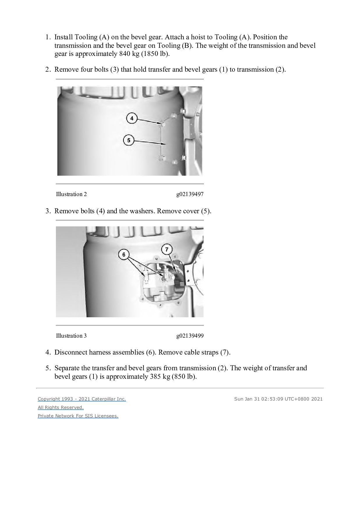
hoist to Tooling (A). Position the transmission and the bevel gear on Tooling (B). The weight of the transmission and bevel gear is approximately 840 kg (1850 lb). 2. Remove four bolts (3) that hold transfer and bevel gears (1) to transmission (2). Illustration 2 g02139497 3. Remove bolts (4) and the washers. Remove cover (5). Illustration 3 g02139499 4. Disconnect harness assemblies (6). Remove cable straps (7). 5. Separate the transfer and bevel gears from transmission (2). The weight of transfer and bevel gears (1) is approximately 385 kg (850 lb). Copyright 1993 - 2021 Caterpillar Inc. All Rights Reserved. Private Network For SIS Licensees. Sun Jan 31 02:53:09 UTC+0800 2021
TRACK-TYPE TRACTOR BMK Configuration: C-9 Engine Rebuild Kit & Related Parts for D6R Series II Tractor BMK00001-UP (MACHINE) Disassembly and Assembly D6R Series II Track-Type Tractor Power Train Media Number -RENR4257-03 Publication Date -01/08/2009 Date Updated -01/09/2009 i03896014 Transmission and Bevel Gears - Connect SMCS - 3010-077 Connection Procedure Table 1 Required Tools Tool Part Number Part Description Qty A 138-7575 Link Bracket 3 B 1P-2420 Transmission Repair Stand 1 Illustration 1 g00839095 1. Inspect the O-ring seals. If necessary, replace the O-ring seals. Position the O-ring seals on the transmission.
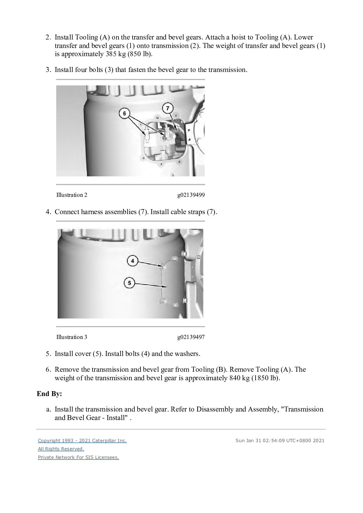
Attach a hoist to Tooling (A). Lower transfer and bevel gears (1) onto transmission (2). The weight of transfer and bevel gears (1) is approximately 385 kg (850 lb). 3. Install four bolts (3) that fasten the bevel gear to the transmission. Illustration 2 g02139499 4. Connect harness assemblies (7). Install cable straps (7). Illustration 3 g02139497 5. Install cover (5). Install bolts (4) and the washers. 6. Remove the transmission and bevel gear from Tooling (B). Remove Tooling (A). The weight of the transmission and bevel gear is approximately 840 kg (1850 lb). End By: a. Install the transmission and bevel gear. Refer to Disassembly and Assembly, "Transmission and Bevel Gear - Install" . Copyright 1993 - 2021 Caterpillar Inc. All Rights Reserved. Private Network For SIS Licensees. Sun Jan 31 02:54:09 UTC+0800 2021
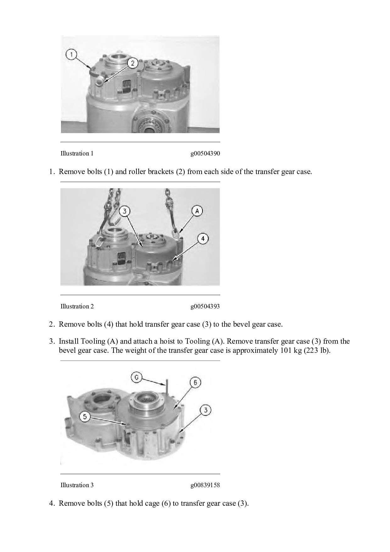
TRACK-TYPE TRACTOR BMK Configuration: C-9 Engine Rebuild Kit & Related Parts for D6R Series II Tractor BMK00001-UP (MACHINE) Disassembly and Assembly D6R Series II Track-Type Tractor Power Train Media Number -RENR4257-03 Publication Date -01/08/2009 Date Updated -01/09/2009 i01621804 Bevel and Transfer Gears - Disassemble SMCS - 3011-015 Disassembly Procedure Table 1 Required Tools Tool Part Number Part Description Qty A 138-7575 Link Bracket 3 B 138-7575 Link Bracket 1 C 8H-0663 Bearing Puller 1 D 8T-2839 Spanner 1 E 1P-1863 Retaining Ring Pliers 1 F 1P-2321 Puller Assembly 1 5P-4170 Step Plate 1 G Forcing Screw (1/2 inch by 13) 2 H Bolt (1/4 inch by 20) 1 Start By: a. Separate the transmission and bevel gears. Note: Put identifying marks on all of the shims as the shims are removed. The identifying marks will ensure correct installation at assembly.
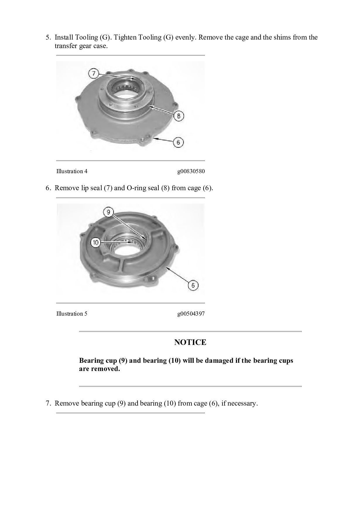
(2) from each side of the transfer gear case. Illustration 2 g00504393 2. Remove bolts (4) that hold transfer gear case (3) to the bevel gear case. 3. Install Tooling (A) and attach a hoist to Tooling (A). Remove transfer gear case (3) from the bevel gear case. The weight of the transfer gear case is approximately 101 kg (223 lb). Illustration 3 g00839158 4. Remove bolts (5) that hold cage (6) to transfer gear case (3).
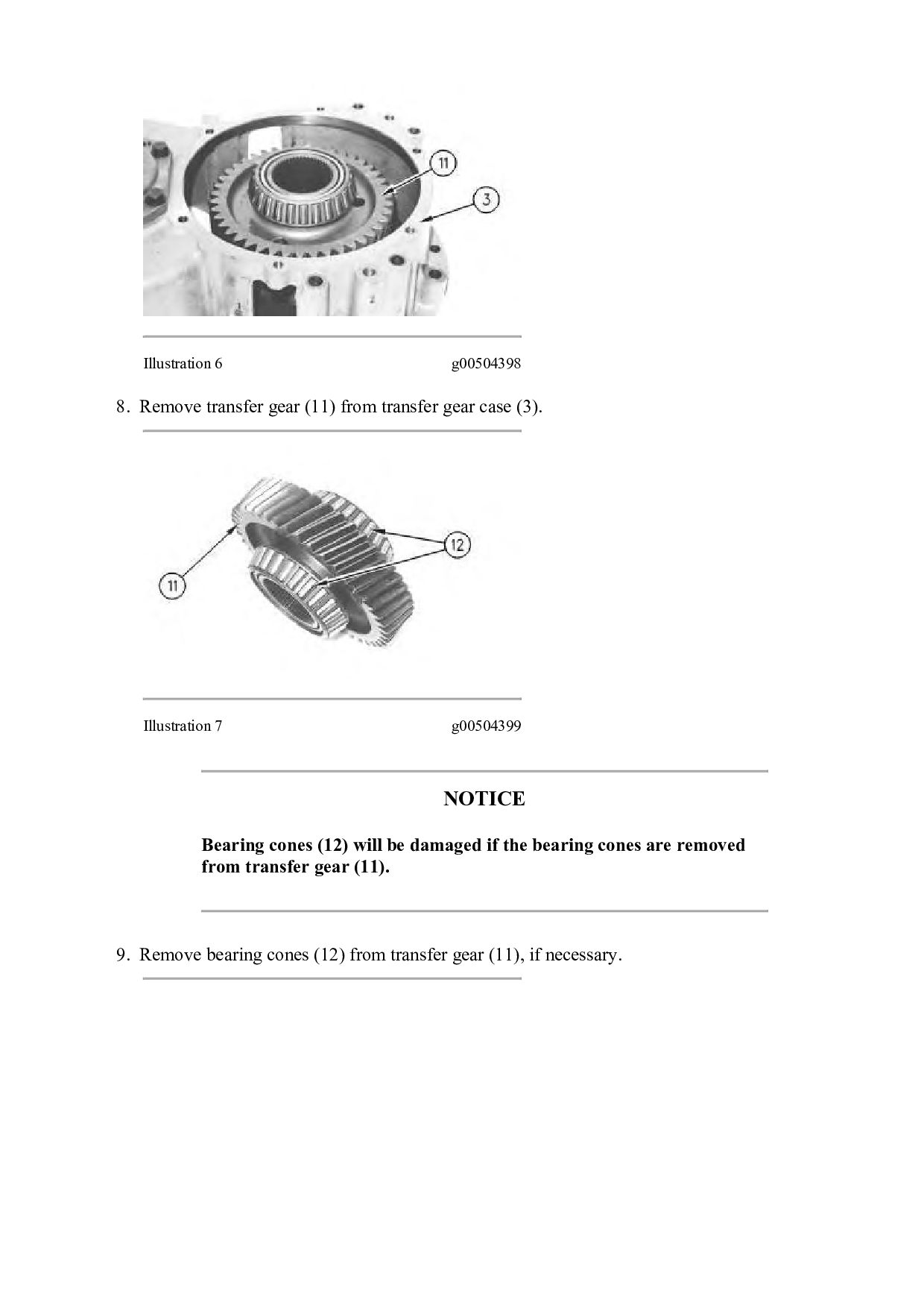
cage and the shims from the transfer gear case. Illustration 4 g00830580 6. Remove lip seal (7) and O-ring seal (8) from cage (6). Illustration 5 g00504397 NOTICE Bearing cup (9) and bearing (10) will be damaged if the bearing cups are removed. 7. Remove bearing cup (9) and bearing (10) from cage (6), if necessary.
gear case (3). Illustration 7 g00504399 NOTICE Bearing cones (12) will be damaged if the bearing cones are removed from transfer gear (11). 9. Remove bearing cones (12) from transfer gear (11), if necessary.
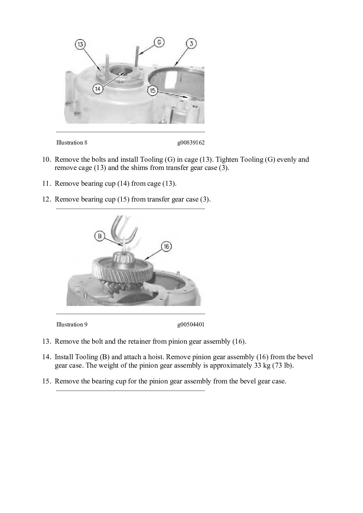
(G) in cage (13). Tighten Tooling (G) evenly and remove cage (13) and the shims from transfer gear case (3). 11. Remove bearing cup (14) from cage (13). 12. Remove bearing cup (15) from transfer gear case (3). Illustration 9 g00504401 13. Remove the bolt and the retainer from pinion gear assembly (16). 14. Install Tooling (B) and attach a hoist. Remove pinion gear assembly (16) from the bevel gear case. The weight of the pinion gear assembly is approximately 33 kg (73 lb). 15. Remove the bearing cup for the pinion gear assembly from the bevel gear case.
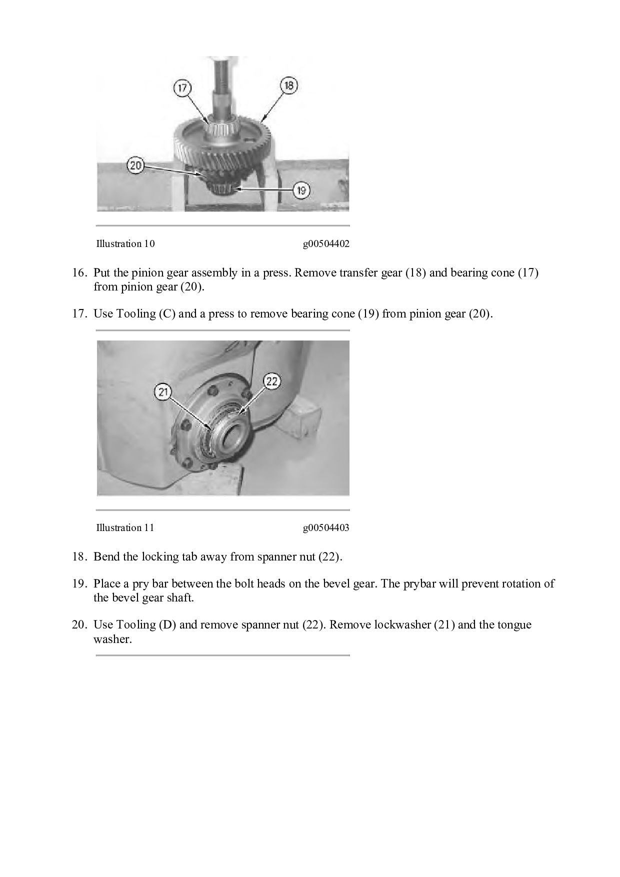
a press. Remove transfer gear (18) and bearing cone (17) from pinion gear (20). 17. Use Tooling (C) and a press to remove bearing cone (19) from pinion gear (20). Illustration 11 g00504403 18. Bend the locking tab away from spanner nut (22). 19. Place a pry bar between the bolt heads on the bevel gear. The prybar will prevent rotation of the bevel gear shaft. 20. Use Tooling (D) and remove spanner nut (22). Remove lockwasher (21) and the tongue washer.
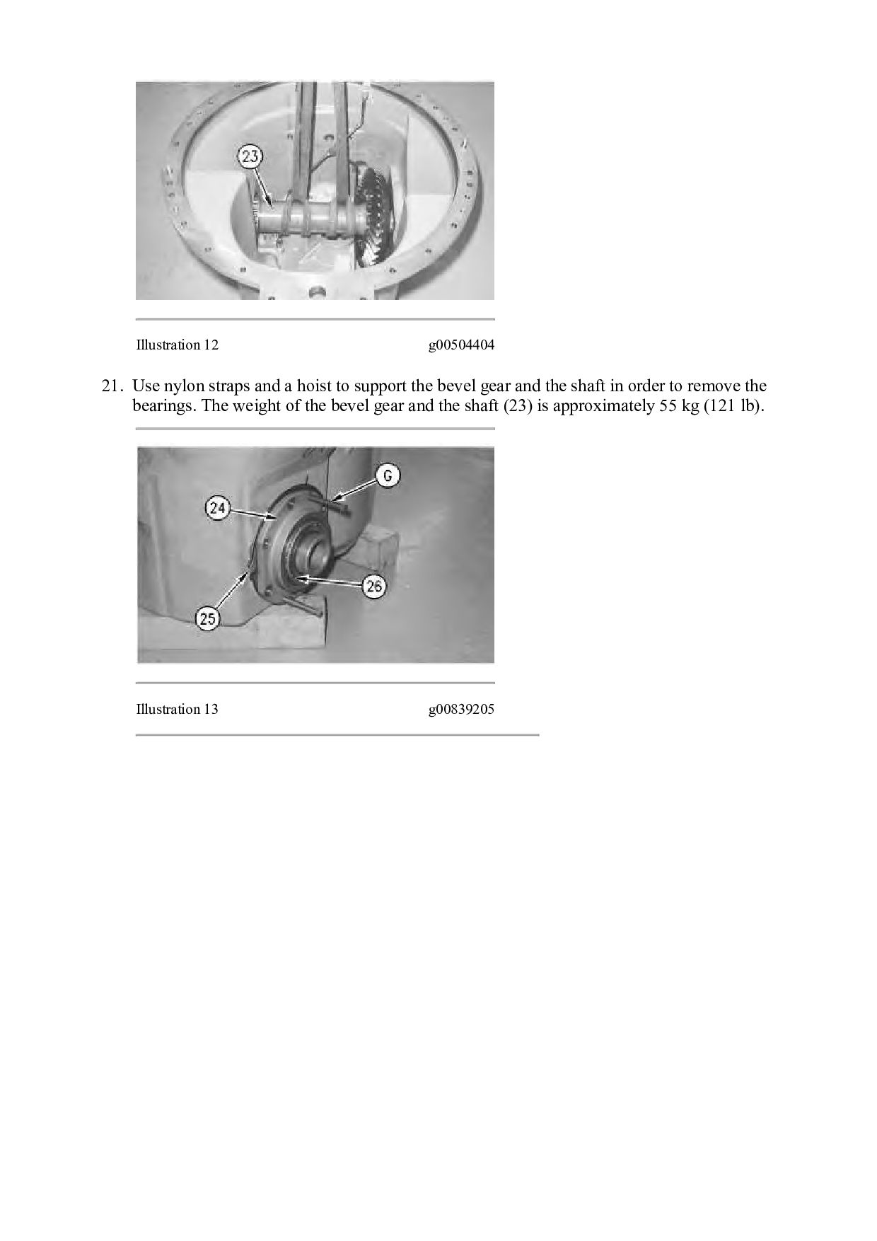
to support the bevel gear and the shaft in order to remove the bearings. The weight of the bevel gear and the shaft (23) is approximately 55 kg (121 lb). Illustration 13 g00839205
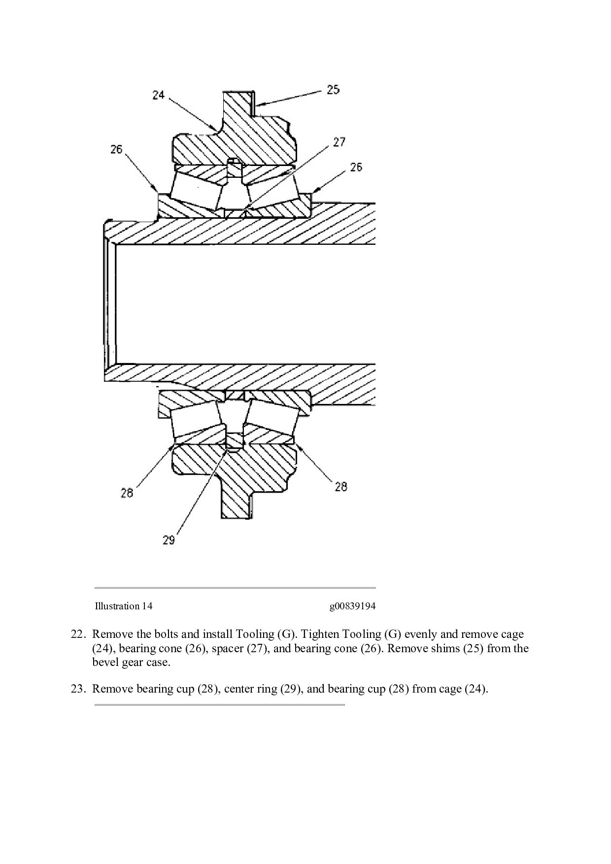
(G). Tighten Tooling (G) evenly and remove cage (24), bearing cone (26), spacer (27), and bearing cone (26). Remove shims (25) from the bevel gear case. 23. Remove bearing cup (28), center ring (29), and bearing cup (28) from cage (24).
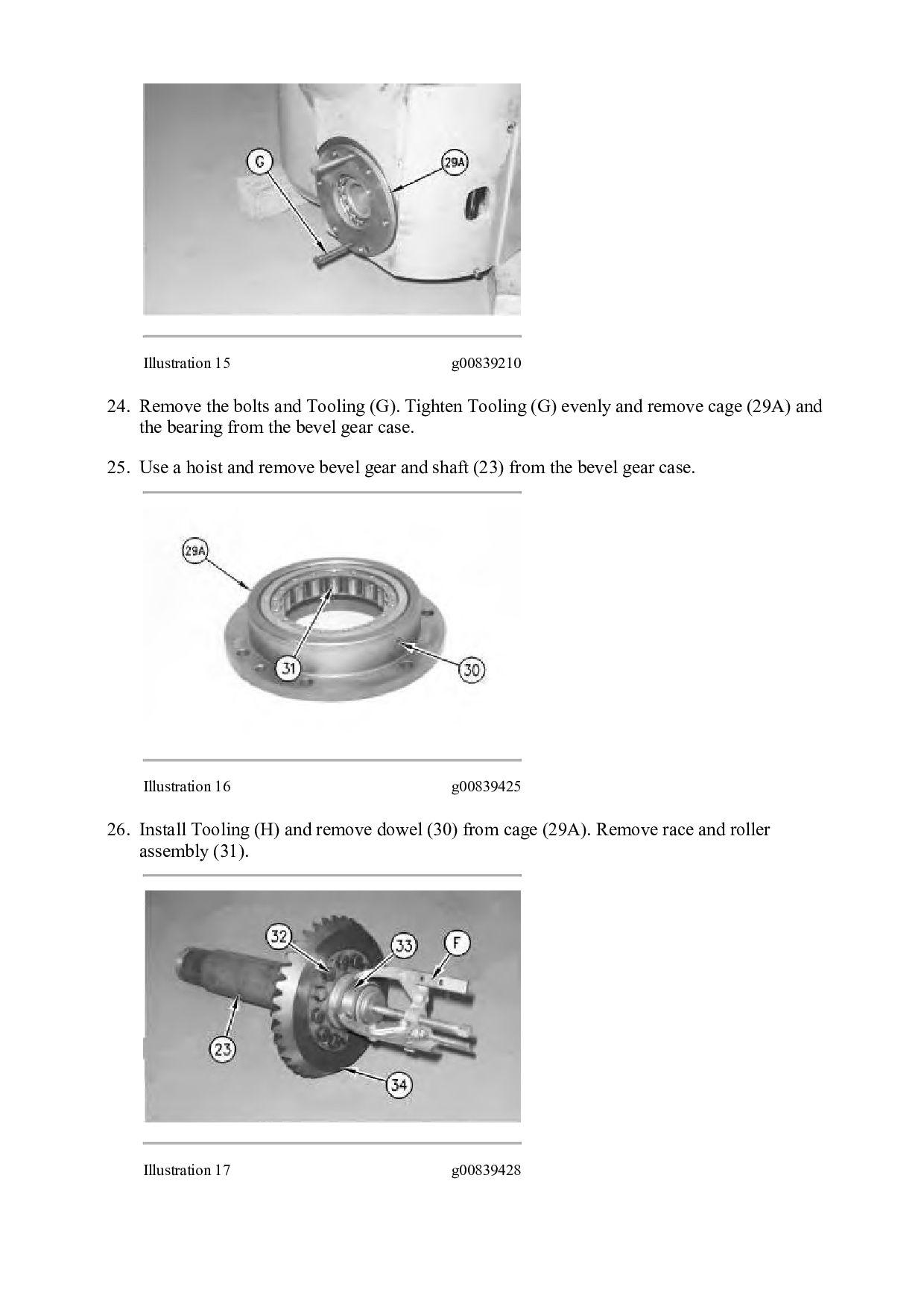
Tighten Tooling (G) evenly and remove cage (29A) and the bearing from the bevel gear case. 25. Use a hoist and remove bevel gear and shaft (23) from the bevel gear case. Illustration 16 g00839425 26. Install Tooling (H) and remove dowel (30) from cage (29A). Remove race and roller assembly (31). Illustration 17 g00839428
bevel gear shaft (23). 28. Use Tooling (F) and remove bearing race (33) from the bevel gear shaft. 29. Remove bolts (32) and the nuts. Install Tooling (H) in bevel gear (34). Tighten Tooling (H) evenly and remove the bevel gear from the bevel gear shaft. 30. Remove the tube assemblies from the bevel gear housing. Copyright 1993 - 2021 Caterpillar Inc. All Rights Reserved. Private Network For SIS Licensees. Sun Jan 31 02:55:08 UTC+0800 2021
Then Get COMPLETE MANUAL. NO WAITING NOTE: If there is no response to click on the link above, please download the PDF document first and then click on it.
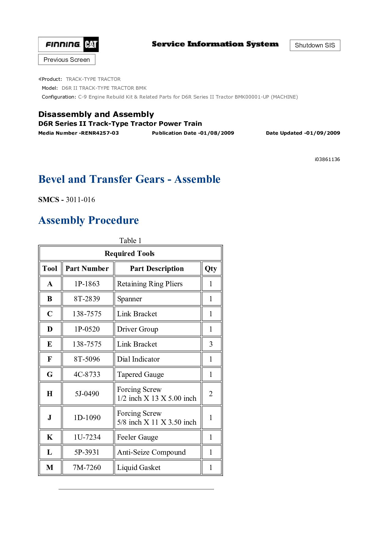
TRACK-TYPE TRACTOR BMK Configuration: C-9 Engine Rebuild Kit & Related Parts for D6R Series II Tractor BMK00001-UP (MACHINE) Disassembly and Assembly D6R Series II Track-Type Tractor Power Train Media Number -RENR4257-03 Publication Date -01/08/2009 Date Updated -01/09/2009 i03861136 Bevel and Transfer Gears - Assemble SMCS - 3011-016 Assembly Procedure Table 1 Required Tools Tool Part Number Part Description Qty A 1P-1863 Retaining Ring Pliers 1 B 8T-2839 Spanner 1 C 138-7575 Link Bracket 1 D 1P-0520 Driver Group 1 E 138-7575 Link Bracket 3 F 8T-5096 Dial Indicator 1 G 4C-8733 Tapered Gauge 1 H 5J-0490 Forcing Screw 1/2 inch X 13 X 5.00 inch 2 J 1D-1090 Forcing Screw 5/8 inch X 11 X 3.50 inch 1 K 1U-7234 Feeler Gauge 1 L 5P-3931 Anti-Seize Compound 1 M 7M-7260 Liquid Gasket 1
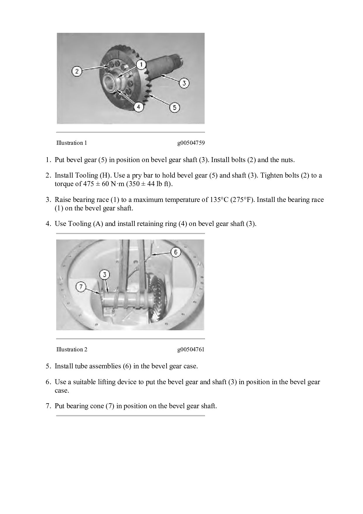
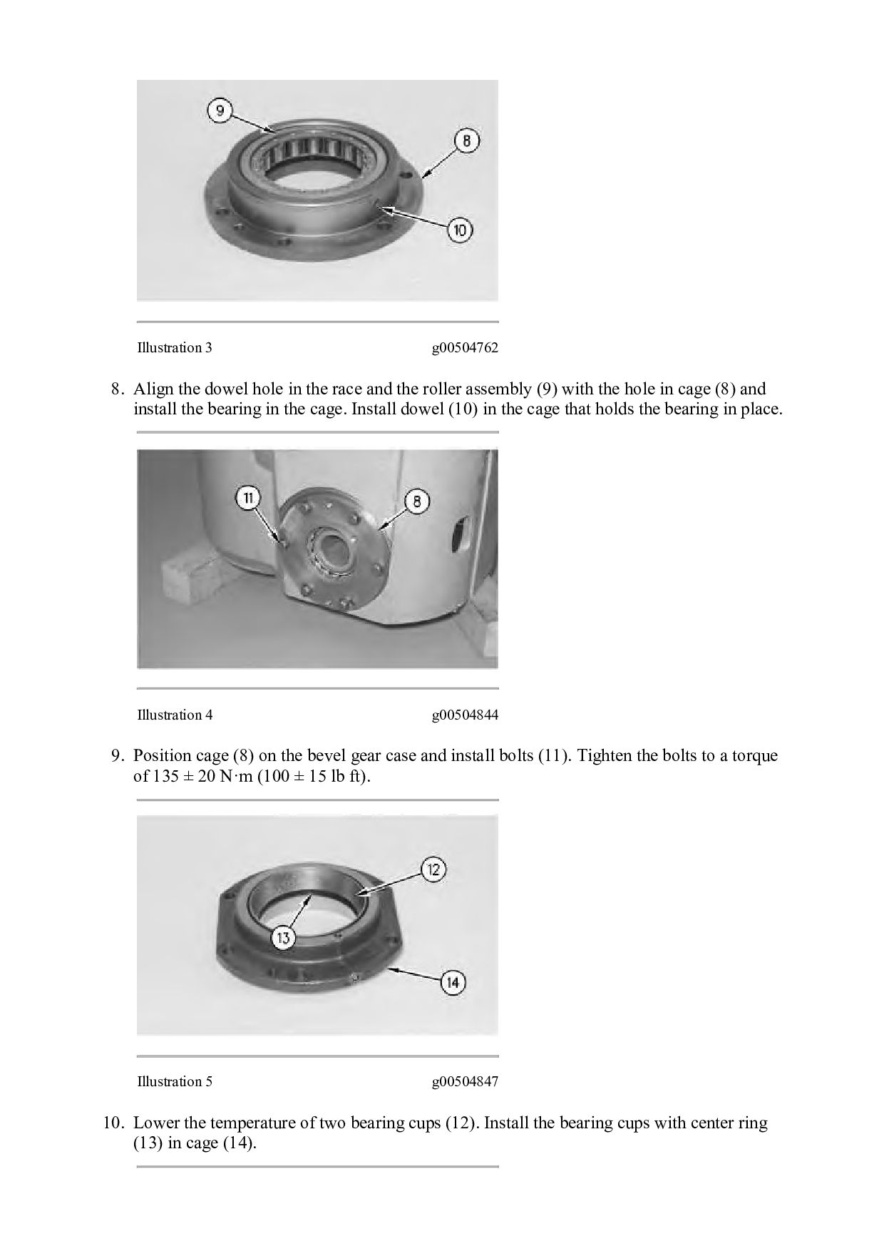
on bevel gear shaft (3). Install bolts (2) and the nuts. 2. Install Tooling (H). Use a pry bar to hold bevel gear (5) and shaft (3). Tighten bolts (2) to a torque of 475 ± 60 N·m (350 ± 44 lb ft). 3. Raise bearing race (1) to a maximum temperature of 135°C (275°F). Install the bearing race (1) on the bevel gear shaft. 4. Use Tooling (A) and install retaining ring (4) on bevel gear shaft (3). Illustration 2 g00504761 5. Install tube assemblies (6) in the bevel gear case. 6. Use a suitable lifting device to put the bevel gear and shaft (3) in position in the bevel gear case. 7. Put bearing cone (7) in position on the bevel gear shaft.
race and the roller assembly (9) with the hole in cage (8) and install the bearing in the cage. Install dowel (10) in the cage that holds the bearing in place. Illustration 4 g00504844 9. Position cage (8) on the bevel gear case and install bolts (11). Tighten the bolts to a torque of 135 ± 20 N·m (100 ± 15 lb ft). Illustration 5 g00504847 10. Lower the temperature of two bearing cups (12). Install the bearing cups with center ring (13) in cage (14).


 dcrfvfbnmk
 lara
 akademiya2063
 aleyda
 frankvandijk
 lauravandoore
 inesmontani
 jcasabona
 kastner
 smashingmag
 axbom