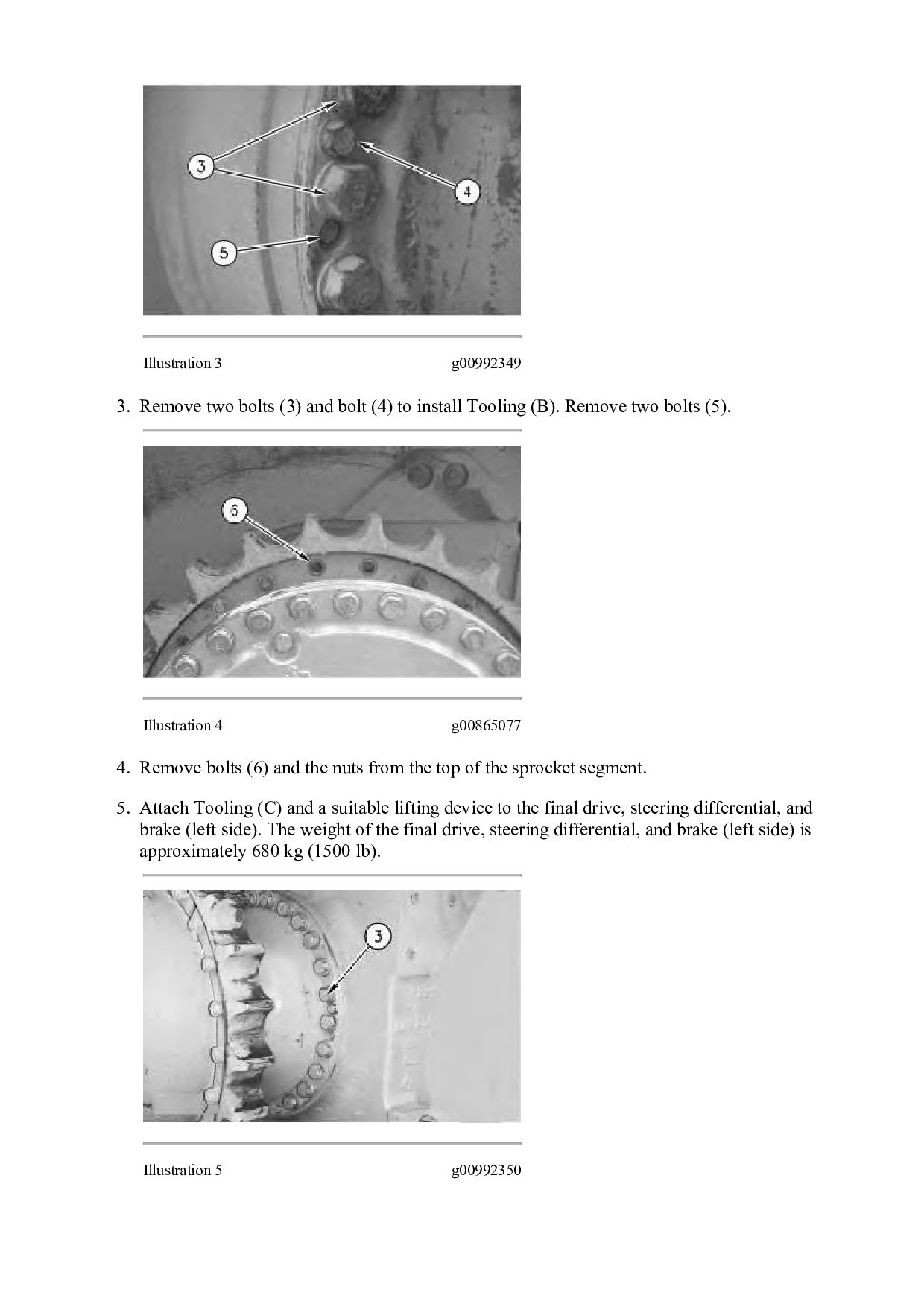
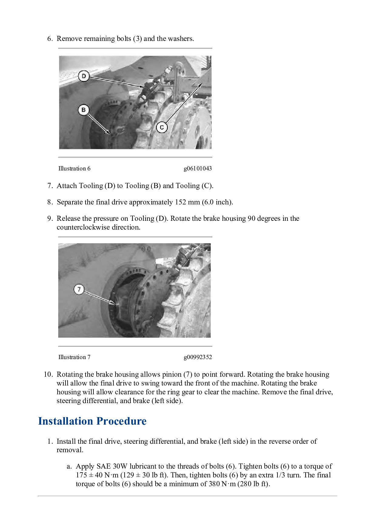
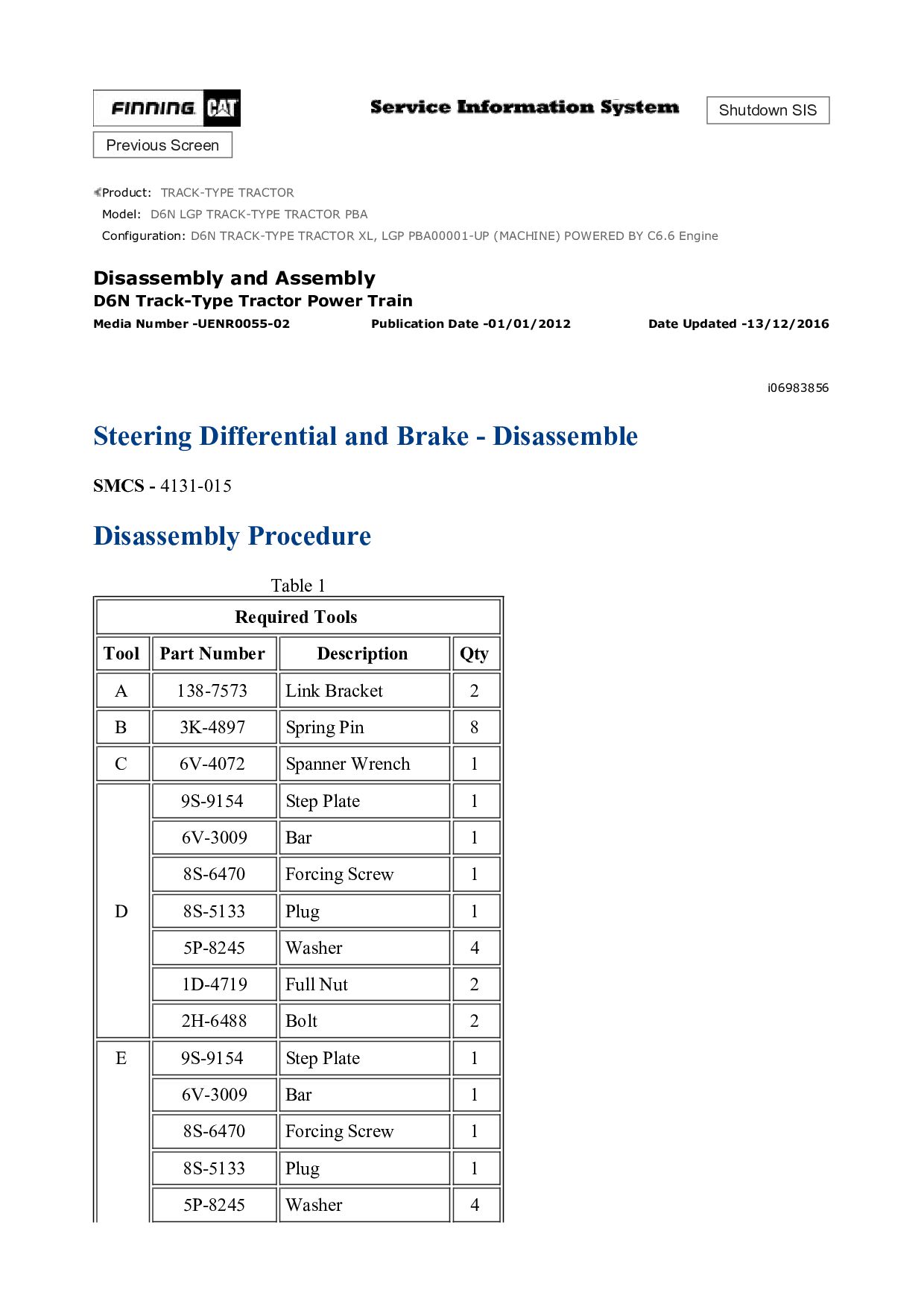
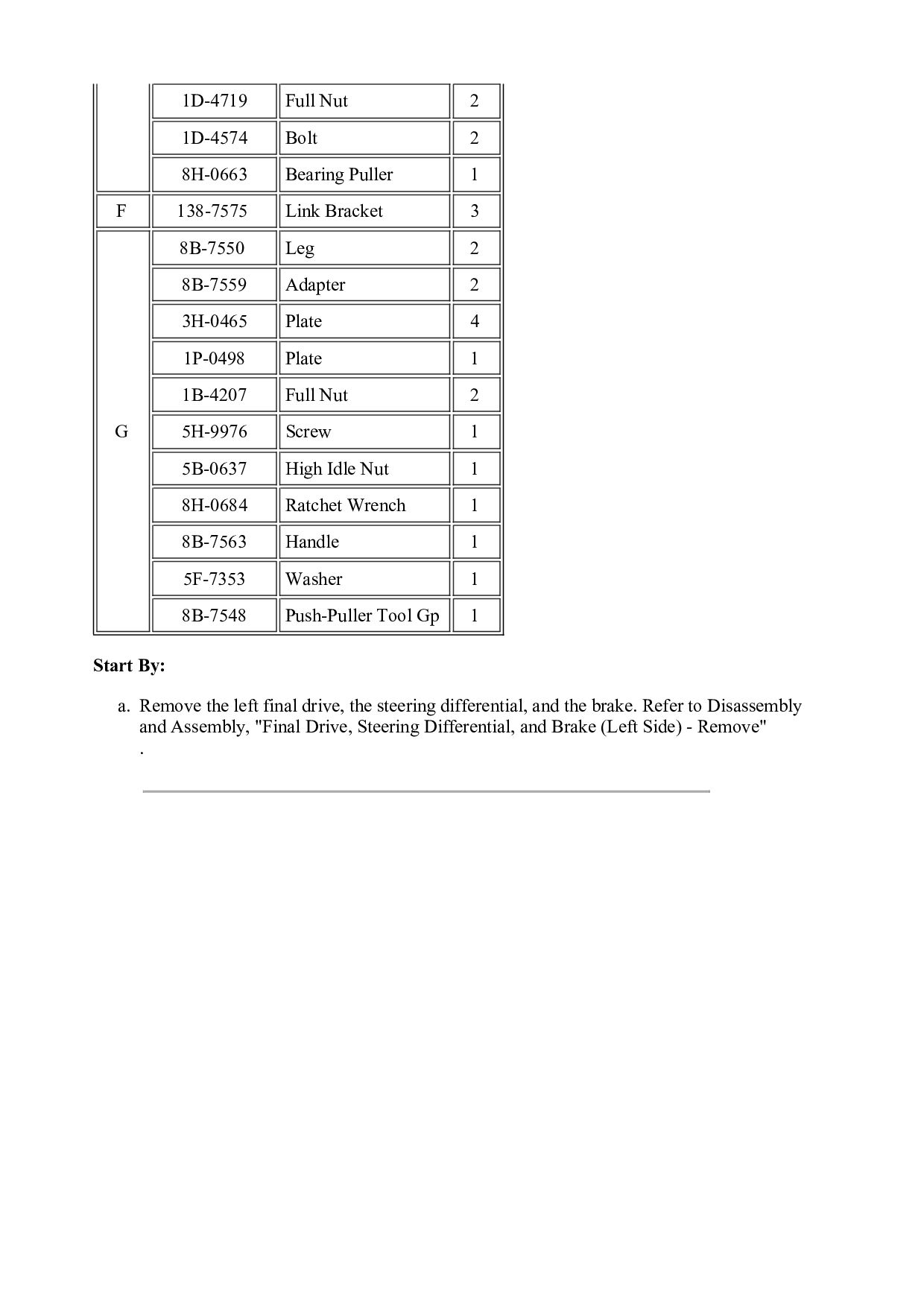
g06101043 7. Attach Tooling (D) to Tooling (B) and Tooling (C). 8. Separate the final drive approximately 152 mm (6.0 inch). 9. Release the pressure on Tooling (D). Rotate the brake housing 90 degrees in the counterclockwise direction. Illustration 7 g00992352 10. Rotating the brake housing allows pinion (7) to point forward. Rotating the brake housing will allow the final drive to swing toward the front of the machine. Rotating the brake housing will allow clearance for the ring gear to clear the machine. Remove the final drive, steering differential, and brake (left side). Installation Procedure 1. Install the final drive, steering differential, and brake (left side) in the reverse order of removal. a. Apply SAE 30W lubricant to the threads of bolts (6). Tighten bolts (6) to a torque of 175 ± 40 N·m (129 ± 30 lb ft). Then, tighten bolts (6) by an extra 1/3 turn. The final torque of bolts (6) should be a minimum of 380 N·m (280 lb ft).