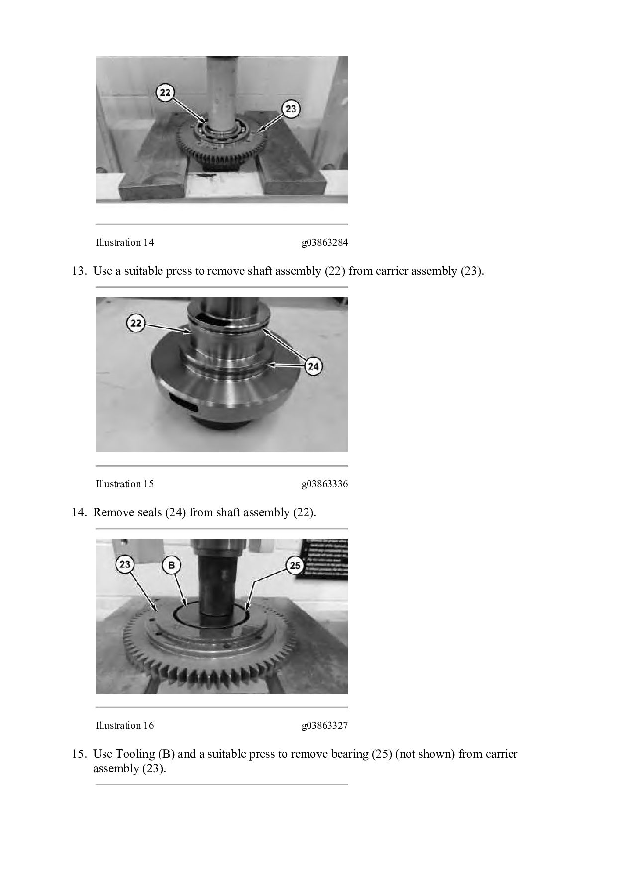
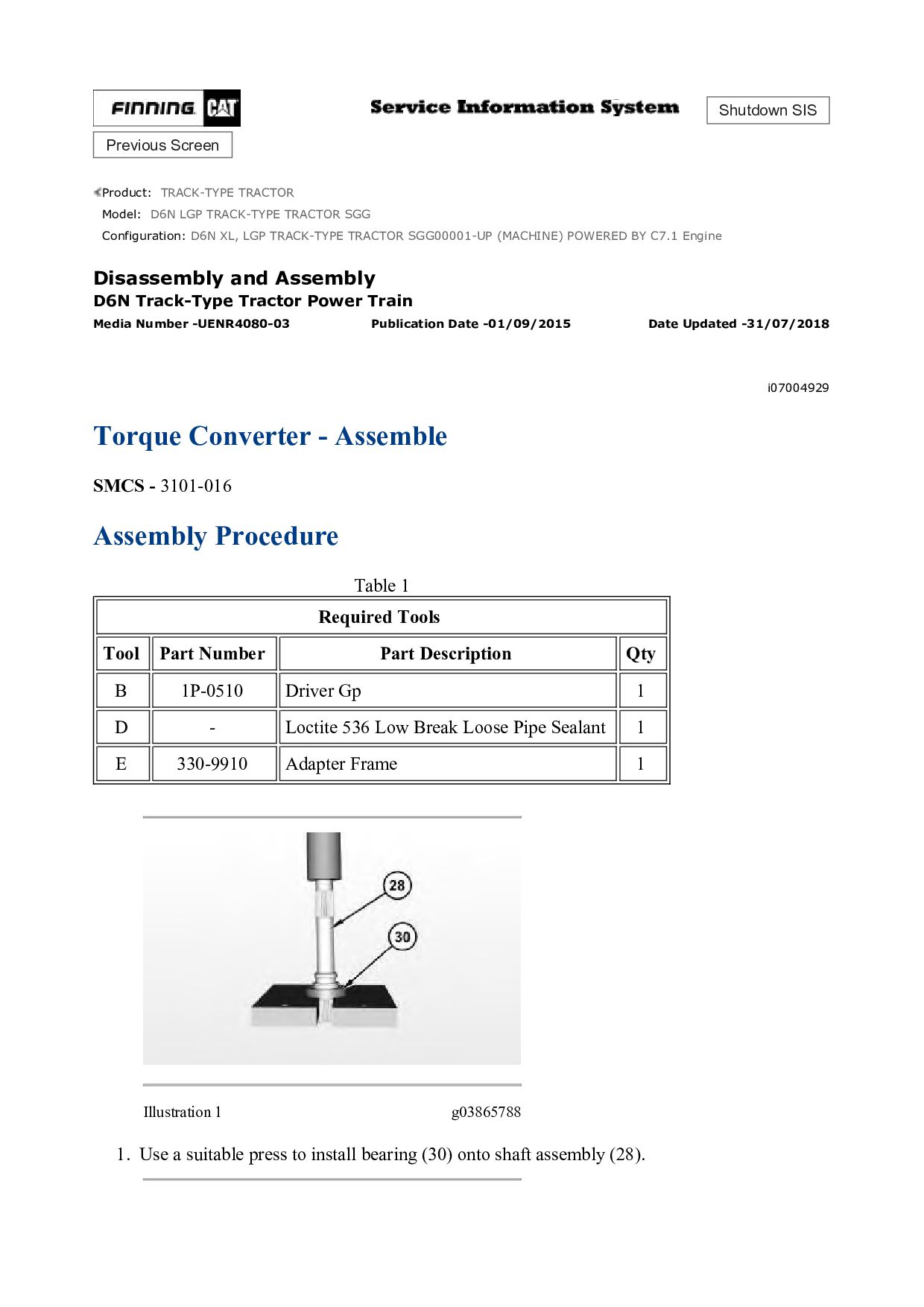
TRACK-TYPE TRACTOR SGG Configuration: D6N XL, LGP TRACK-TYPE TRACTOR SGG00001-UP (MACHINE) POWERED BY C7.1 Engine Disassembly and Assembly D6N Track-Type Tractor Power Train Media Number -UENR4080-03 Publication Date -01/09/2015 Date Updated -31/07/2018 i07021596 Torque Converter - Disassemble SMCS - 3101-015 Disassembly Procedure Table 1 Required Tools Tool Part Number Part Description Qty A 8T-4172 Bolt 2 B 1P-0510 Driver Gp 1 C 8H-0663 Bearing Puller Gp 1 Start By: a. Remove the torque converter. NOTICE Care must be taken to ensure that fluids are contained during performance of inspection, maintenance, testing, adjusting, and repair of the product. Be prepared to collect the fluid with suitable containers before opening any compartment or disassembling any component containing fluids. Refer to Special Publication, NENG2500, "Dealer Service Tool Catalog" for tools and supplies suitable to collect and contain fluids on Cat® products. Dispose of all fluids according to local regulations and mandates.
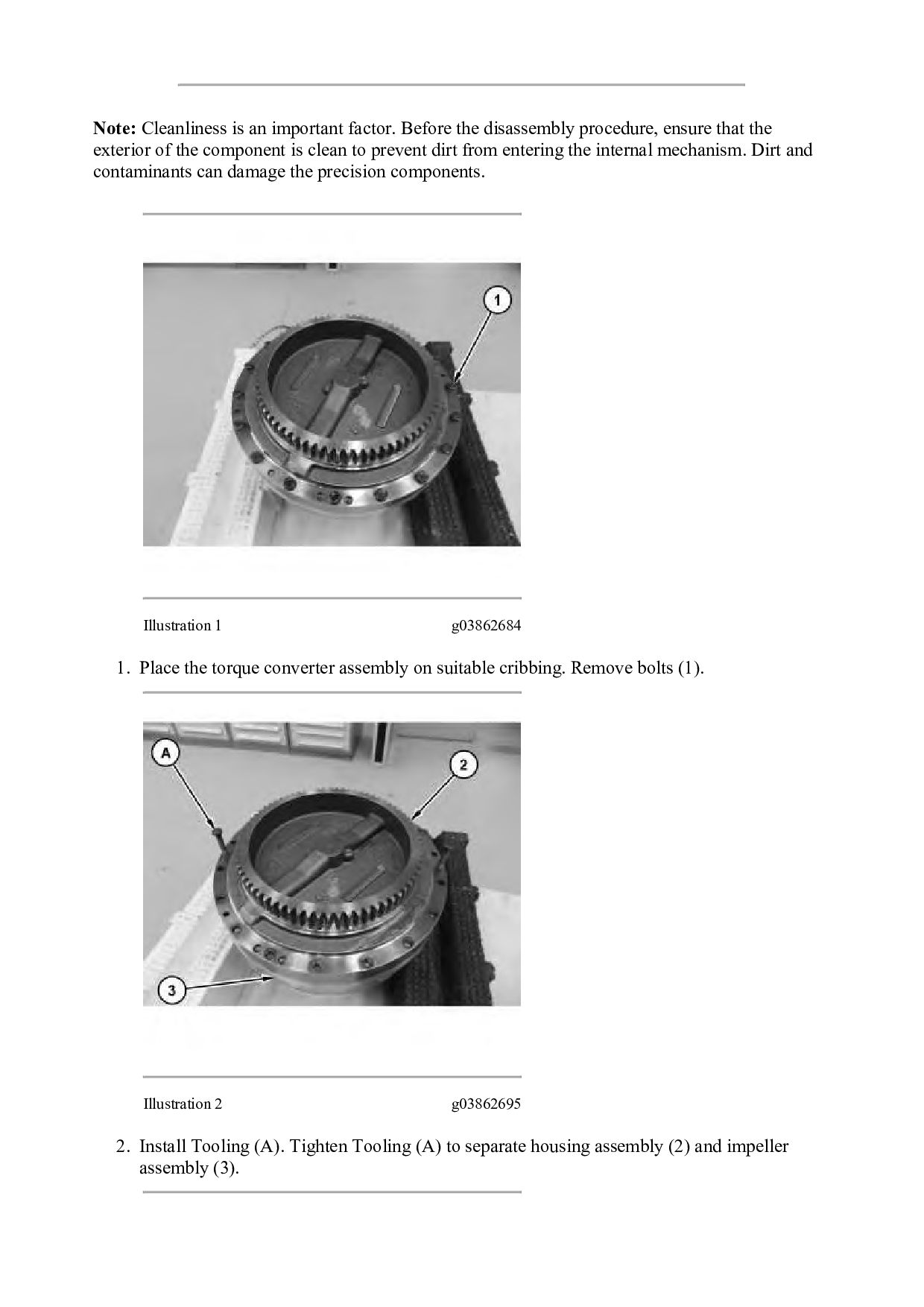
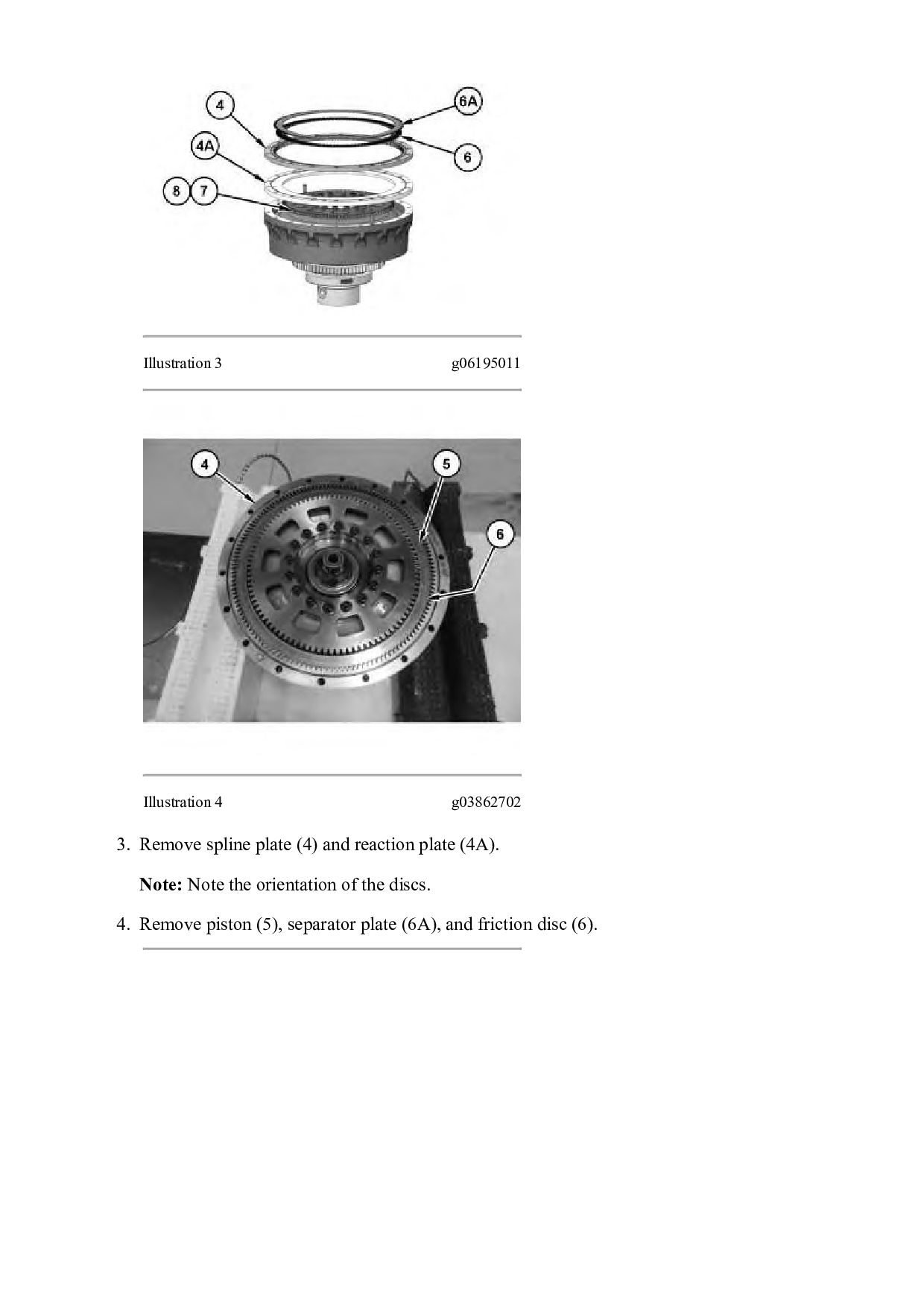
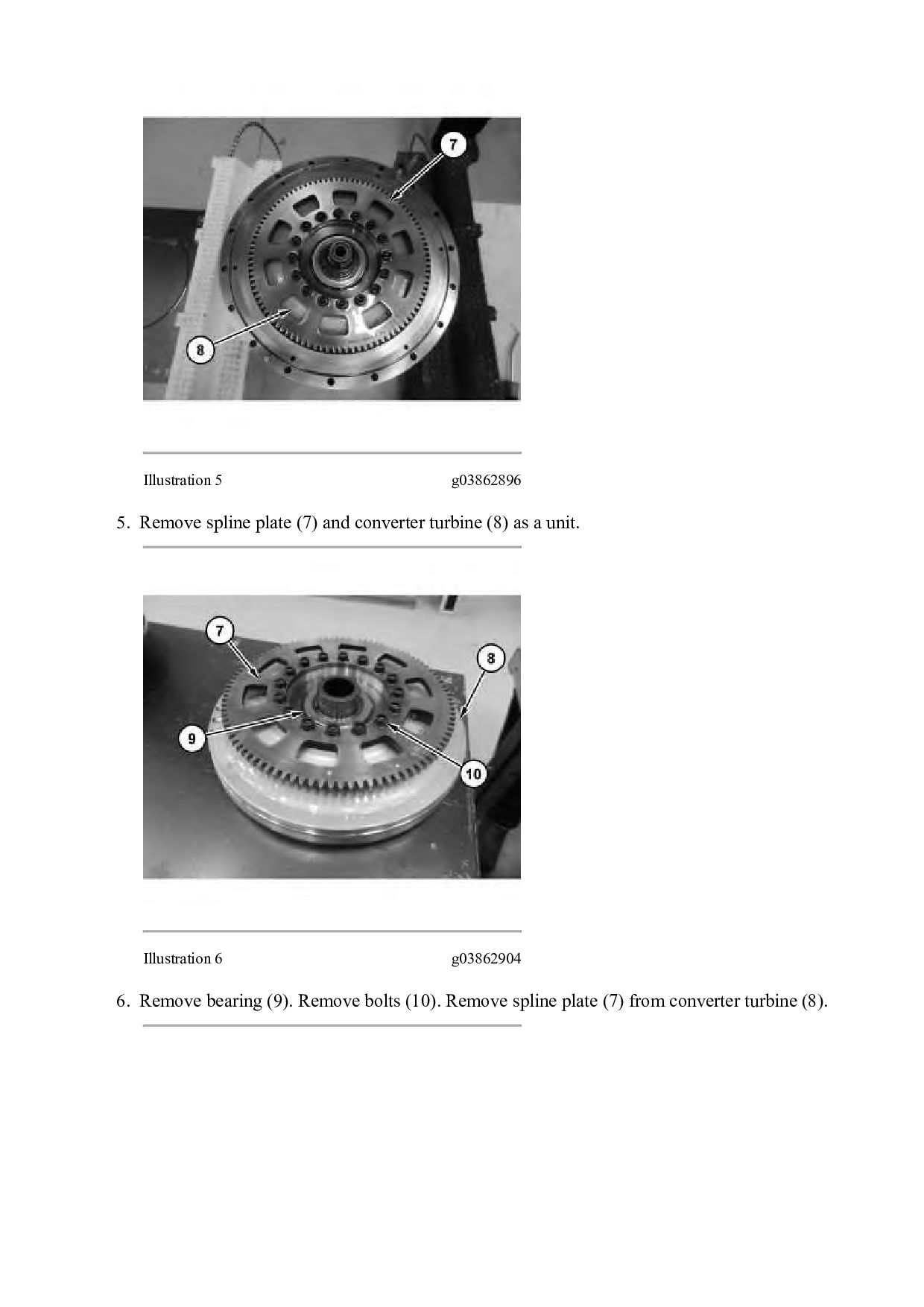
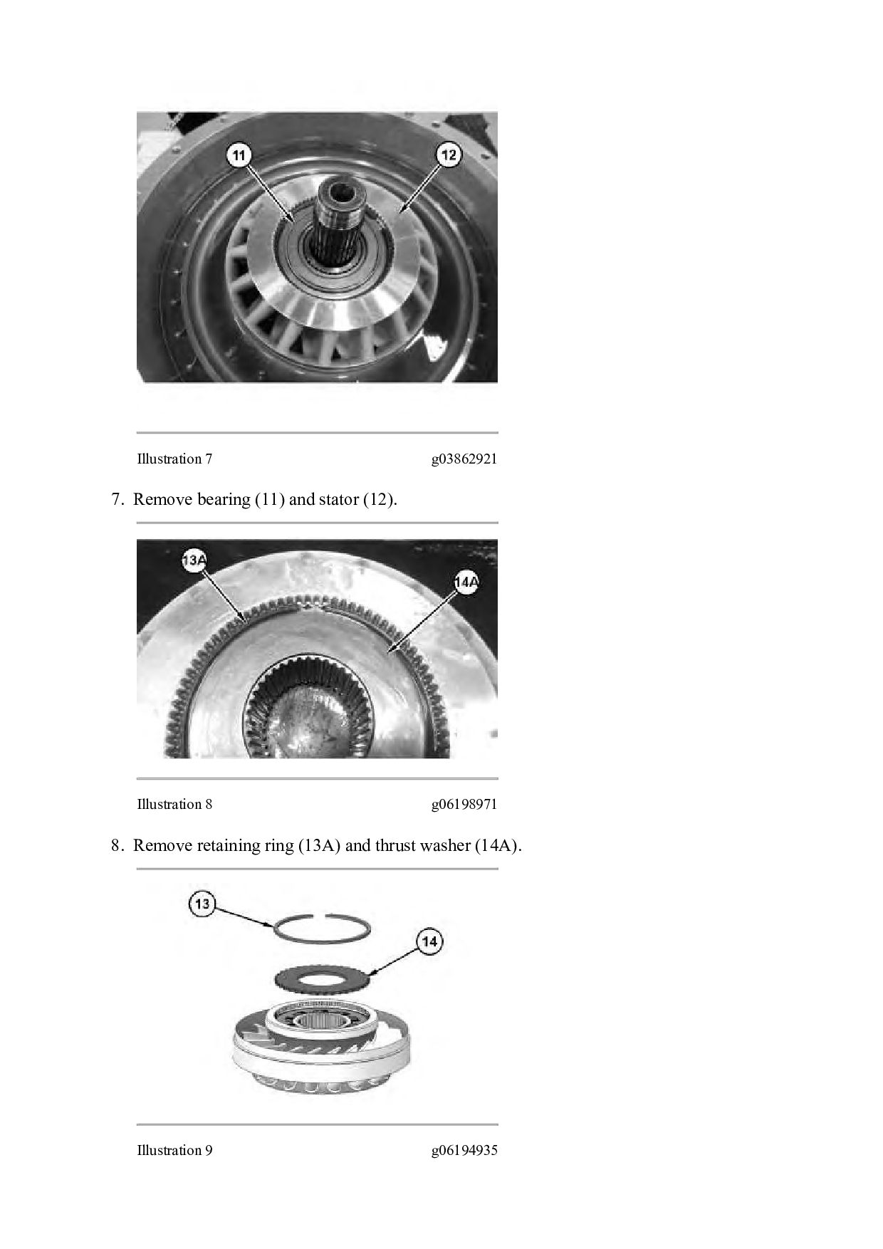
ensure that the exterior of the component is clean to prevent dirt from entering the internal mechanism. Dirt and contaminants can damage the precision components. Illustration 1 g03862684 1. Place the torque converter assembly on suitable cribbing. Remove bolts (1). Illustration 2 g03862695 2. Install Tooling (A). Tighten Tooling (A) to separate housing assembly (2) and impeller assembly (3).
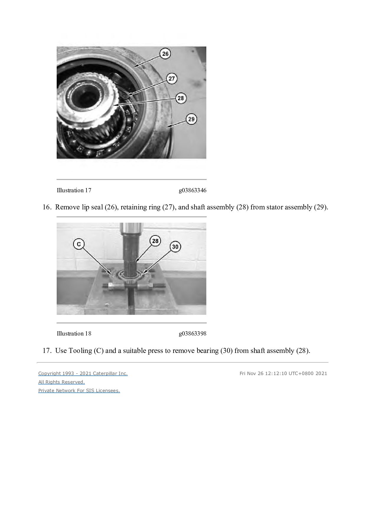
(27), and shaft assembly (28) from stator assembly (29). Illustration 18 g03863398 17. Use Tooling (C) and a suitable press to remove bearing (30) from shaft assembly (28). Copyright 1993 - 2021 Caterpillar Inc. All Rights Reserved. Private Network For SIS Licensees. Fri Nov 26 12:12:10 UTC+0800 2021
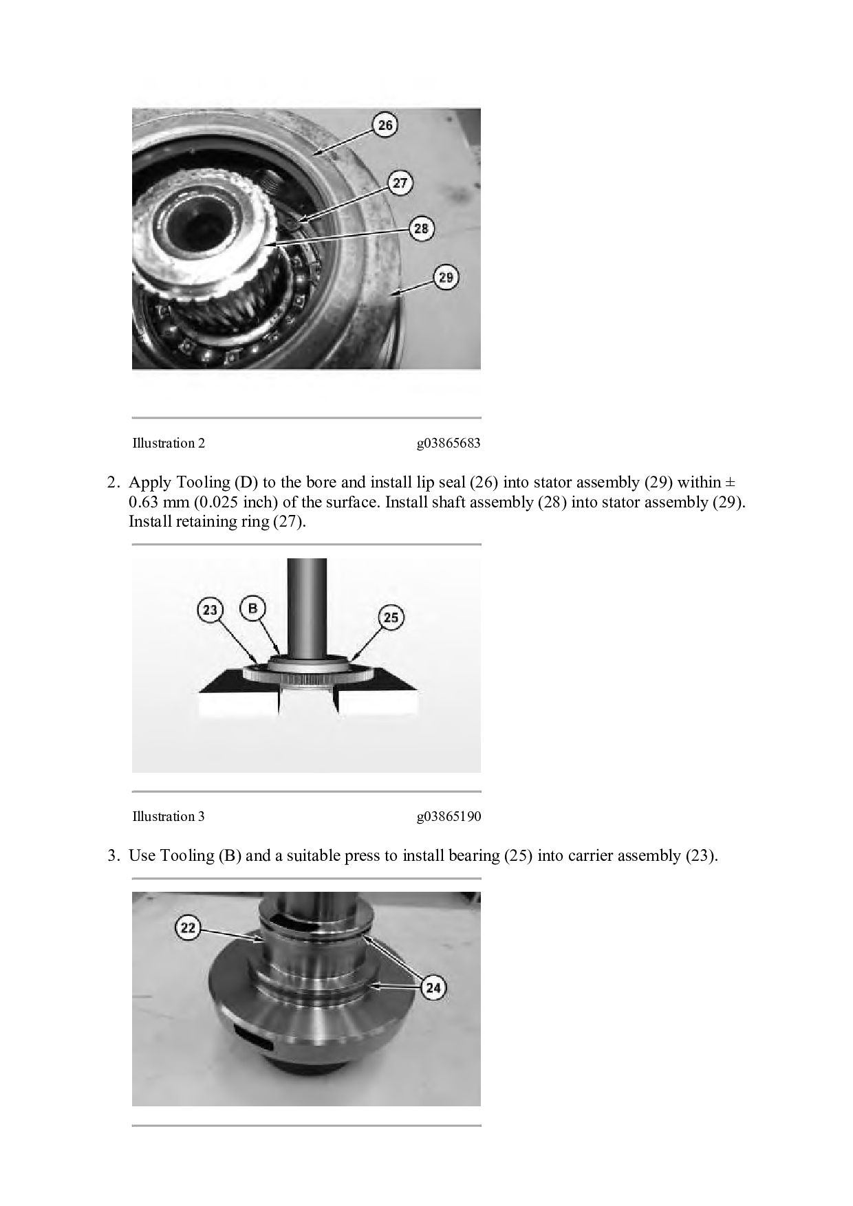
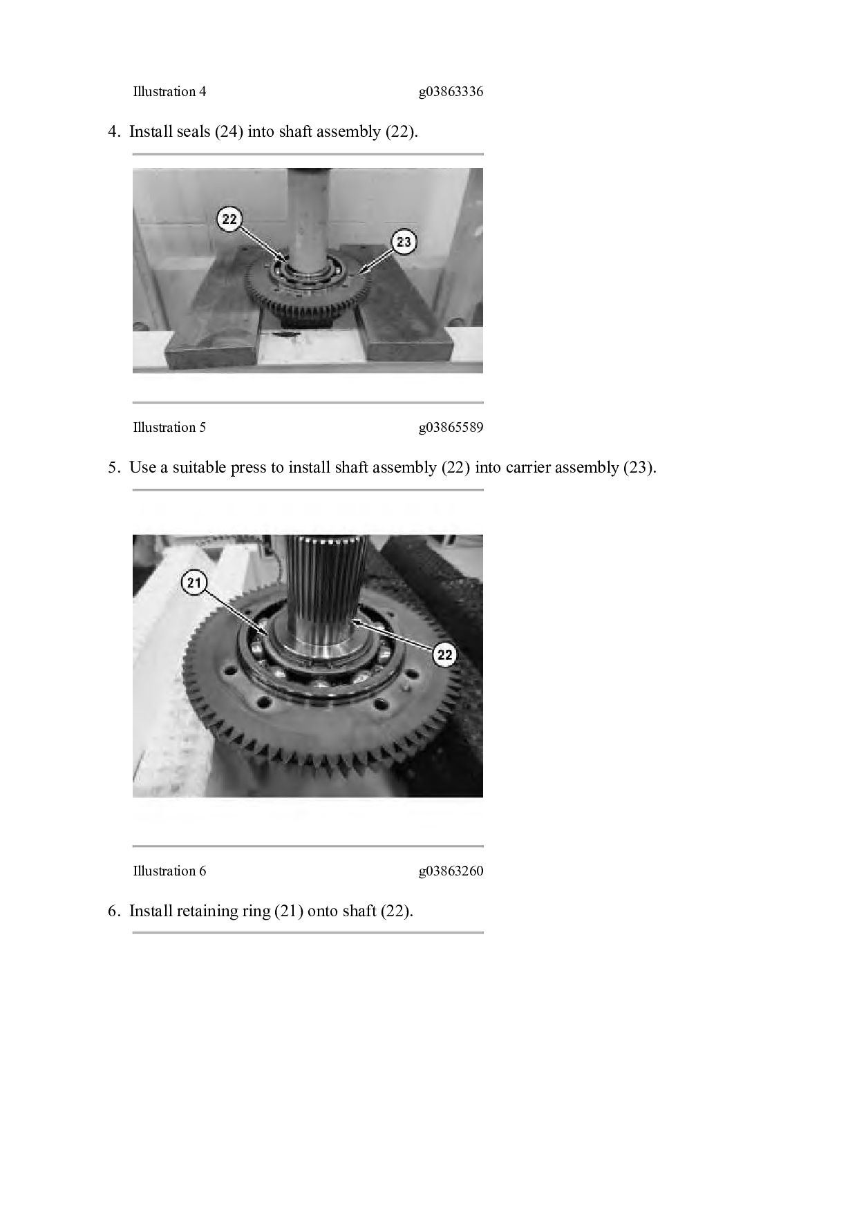
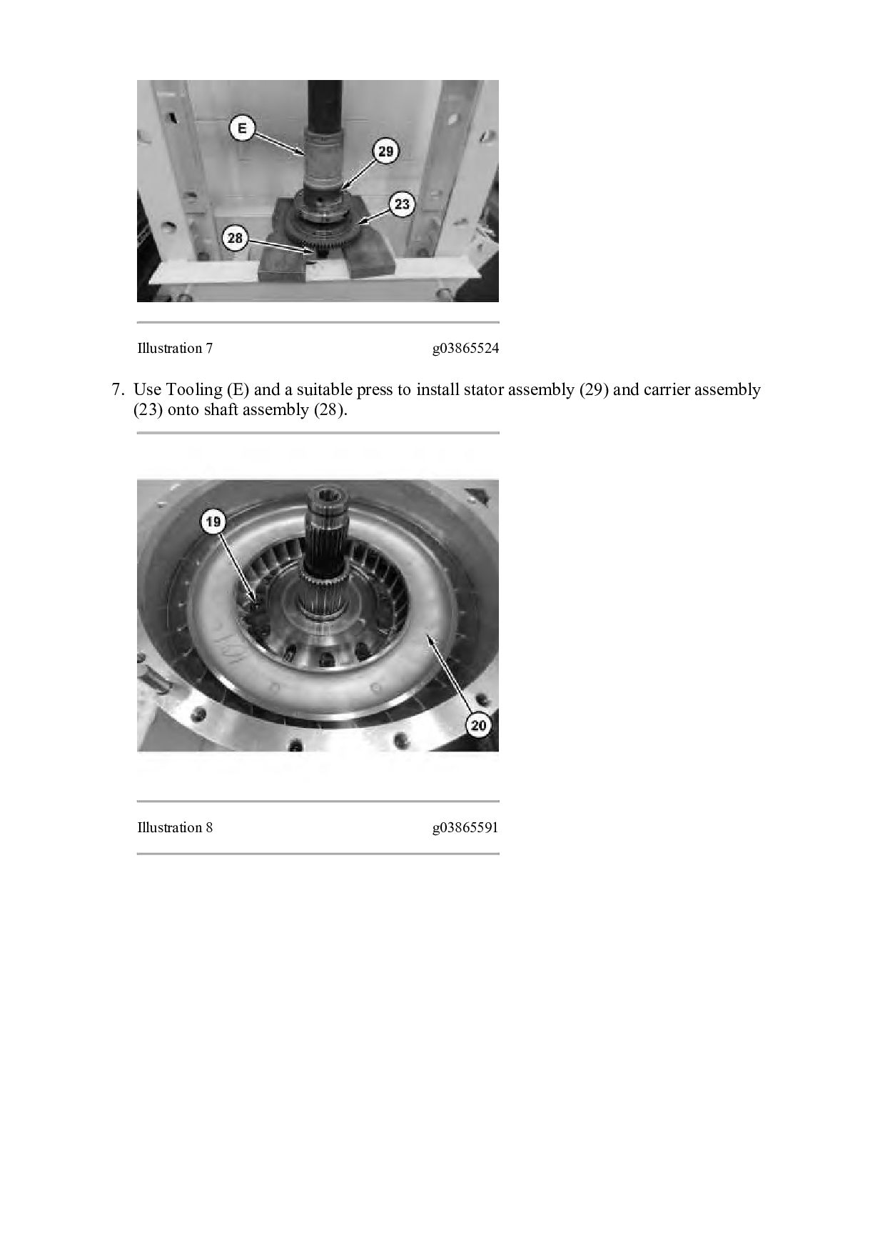
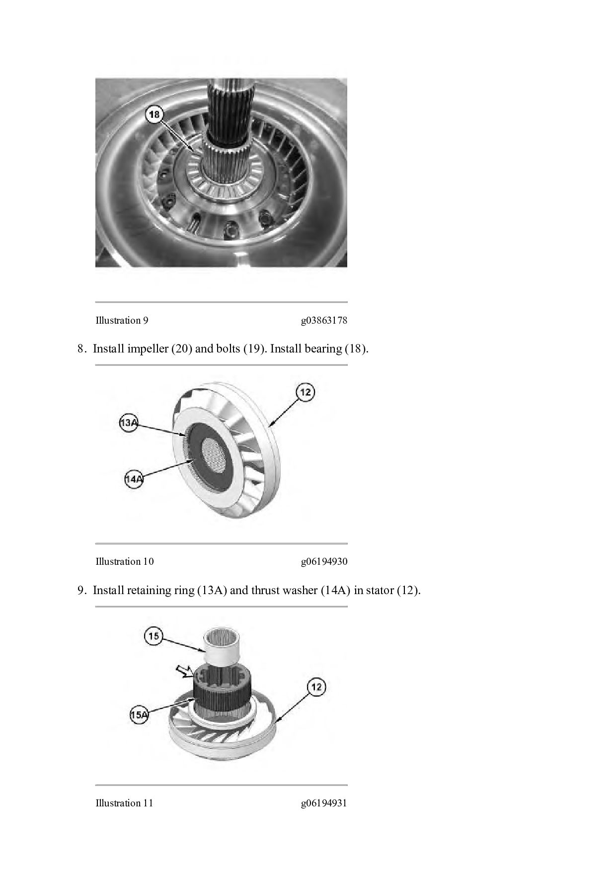
and install lip seal (26) into stator assembly (29) within ± 0.63 mm (0.025 inch) of the surface. Install shaft assembly (28) into stator assembly (29). Install retaining ring (27). Illustration 3 g03865190 3. Use Tooling (B) and a suitable press to install bearing (25) into carrier assembly (23).
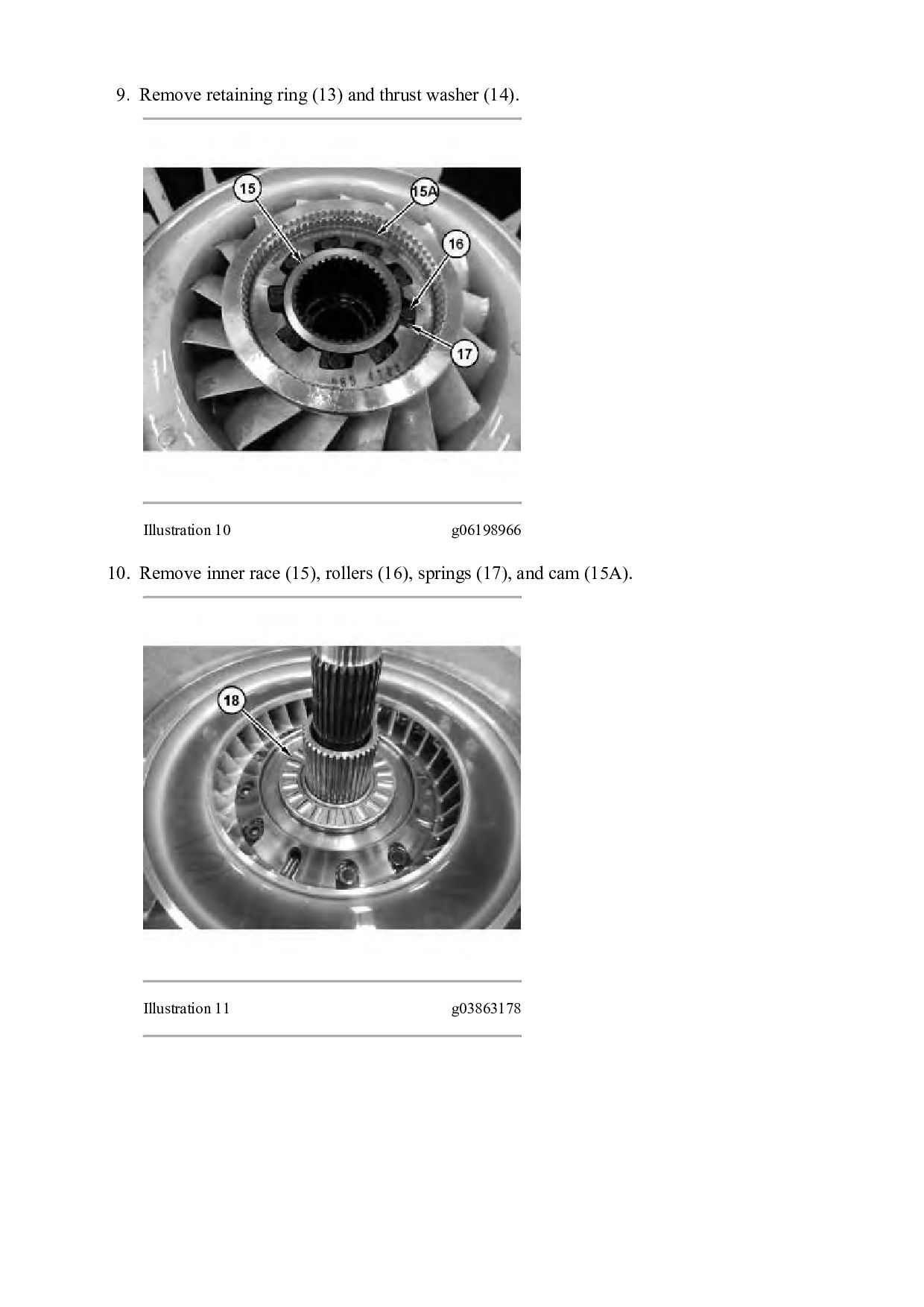
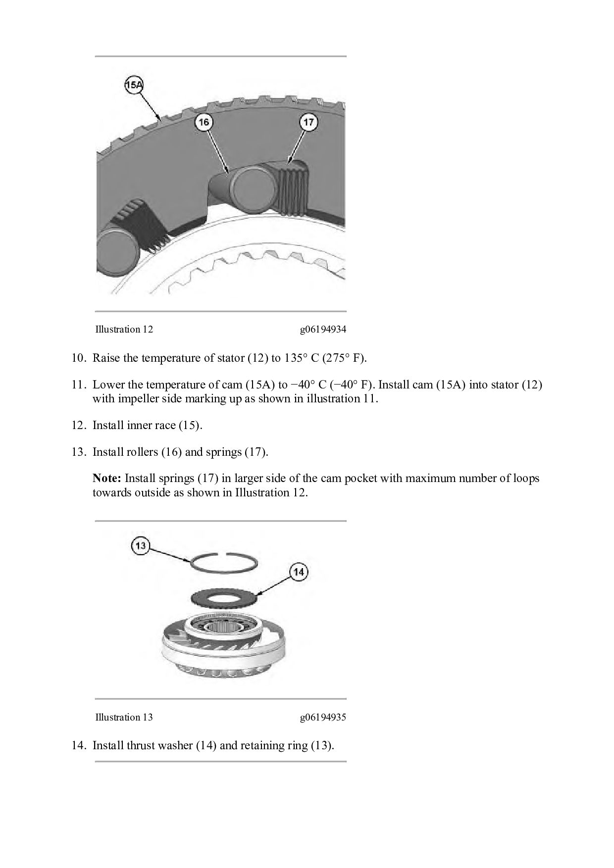
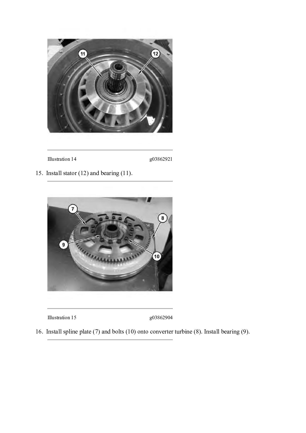
to 135° C (275° F). 11. Lower the temperature of cam (15A) to −40° C (−40° F). Install cam (15A) into stator (12) with impeller side marking up as shown in illustration 11. 12. Install inner race (15). 13. Install rollers (16) and springs (17). Note: Install springs (17) in larger side of the cam pocket with maximum number of loops towards outside as shown in Illustration 12. Illustration 13 g06194935 14. Install thrust washer (14) and retaining ring (13).
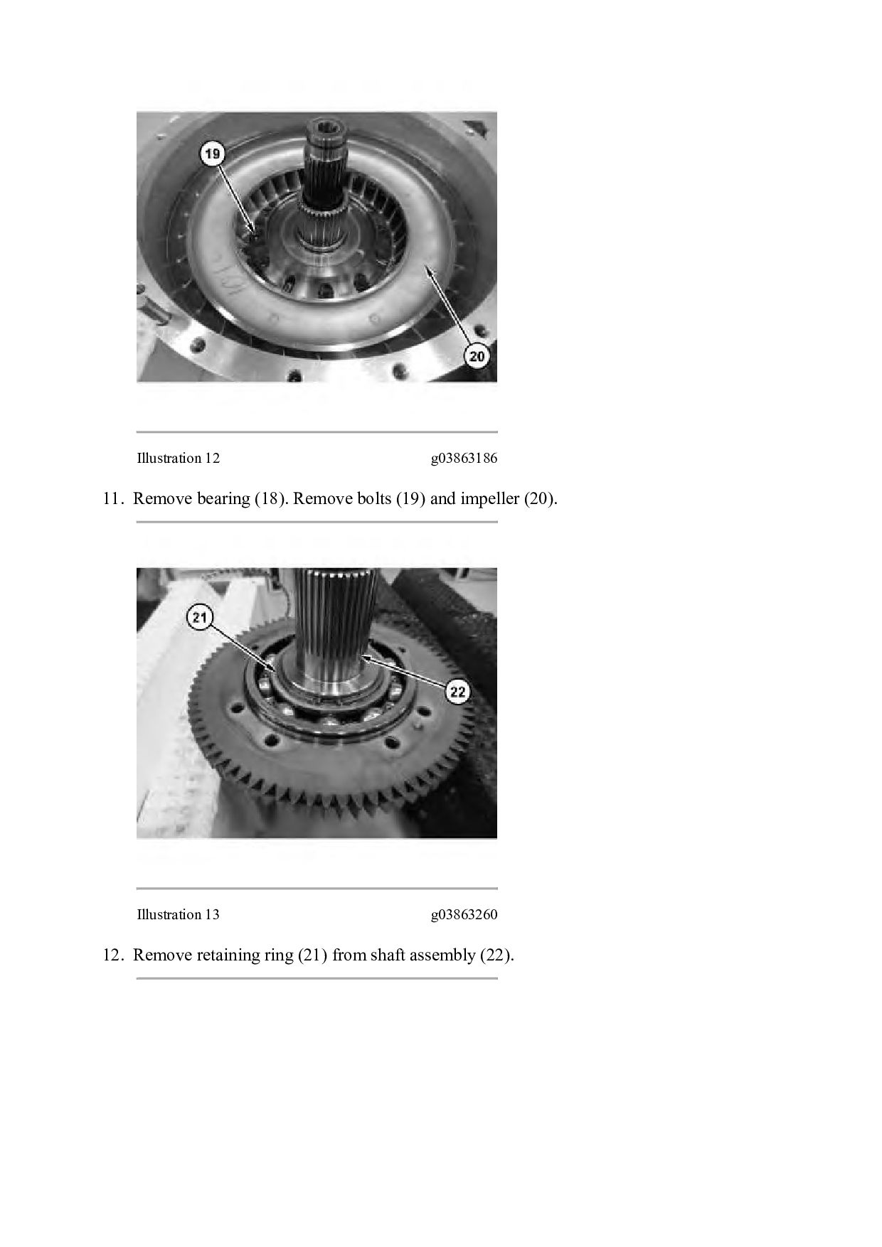
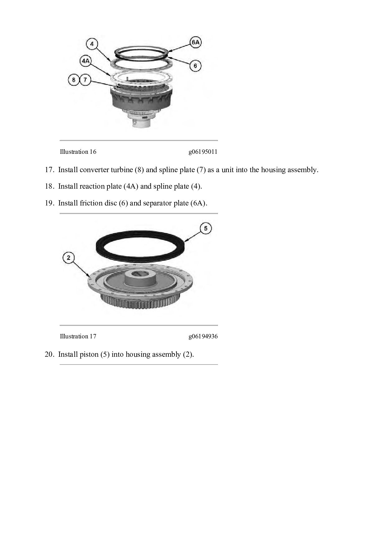
plate (7) as a unit into the housing assembly. 18. Install reaction plate (4A) and spline plate (4). 19. Install friction disc (6) and separator plate (6A). Illustration 17 g06194936 20. Install piston (5) into housing assembly (2).
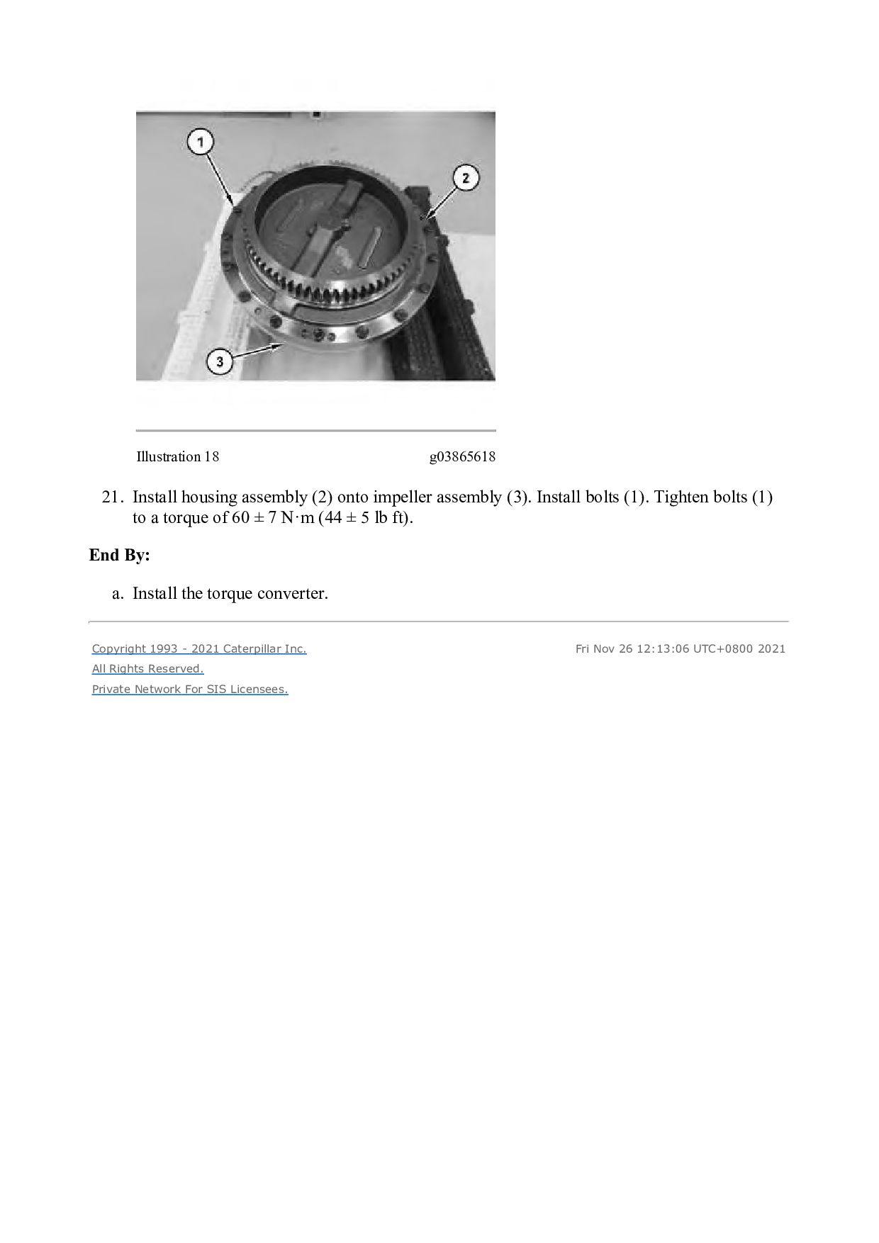
assembly (3). Install bolts (1). Tighten bolts (1) to a torque of 60 ± 7 N·m (44 ± 5 lb ft). End By: a. Install the torque converter. Copyright 1993 - 2021 Caterpillar Inc. All Rights Reserved. Private Network For SIS Licensees. Fri Nov 26 12:13:06 UTC+0800 2021
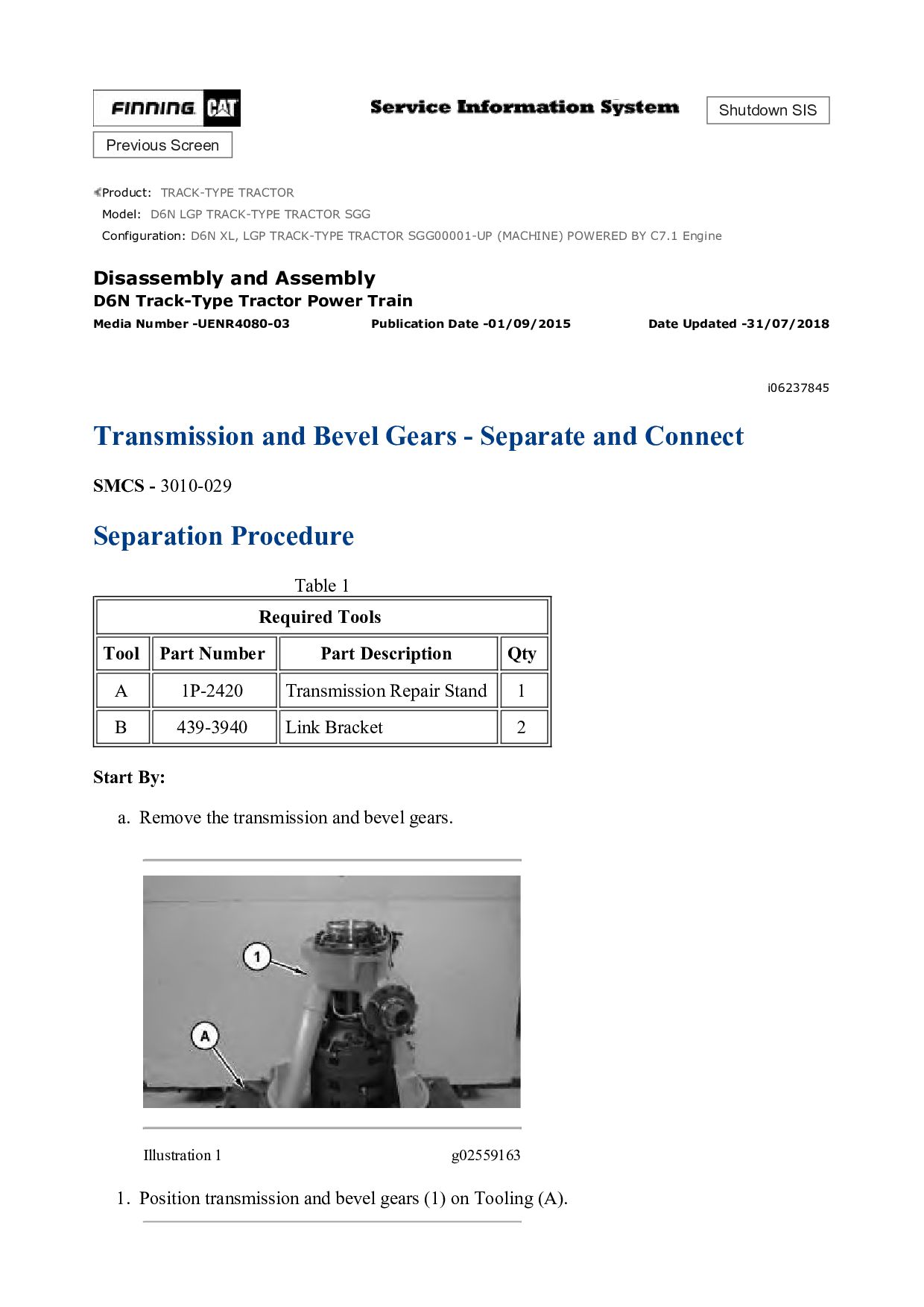
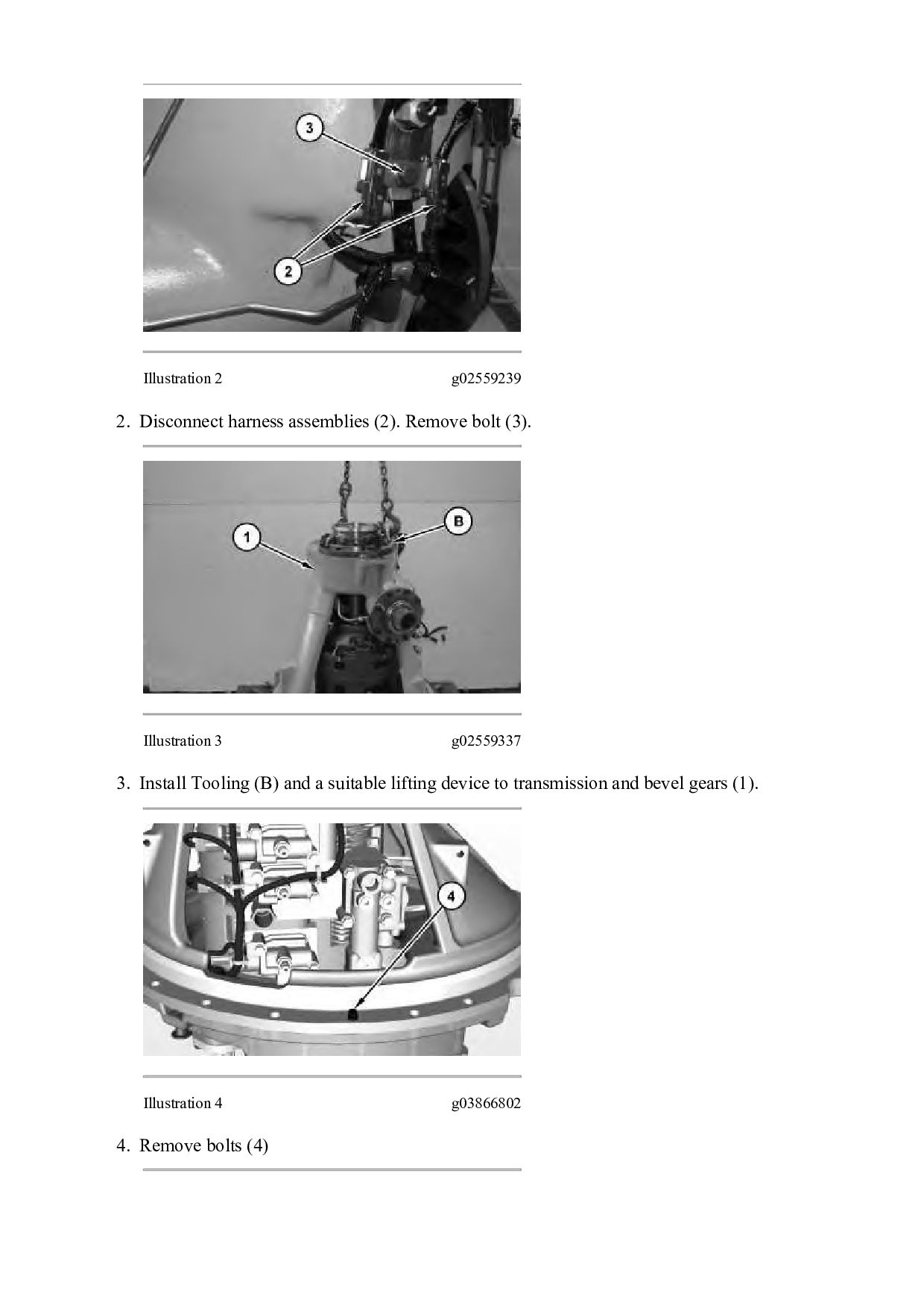
TRACK-TYPE TRACTOR SGG Configuration: D6N XL, LGP TRACK-TYPE TRACTOR SGG00001-UP (MACHINE) POWERED BY C7.1 Engine Disassembly and Assembly D6N Track-Type Tractor Power Train Media Number -UENR4080-03 Publication Date -01/09/2015 Date Updated -31/07/2018 i06237845 Transmission and Bevel Gears - Separate and Connect SMCS - 3010-029 Separation Procedure Table 1 Required Tools Tool Part Number Part Description Qty A 1P-2420 Transmission Repair Stand 1 B 439-3940 Link Bracket 2 Start By: a. Remove the transmission and bevel gears. Illustration 1 g02559163 1. Position transmission and bevel gears (1) on Tooling (A).
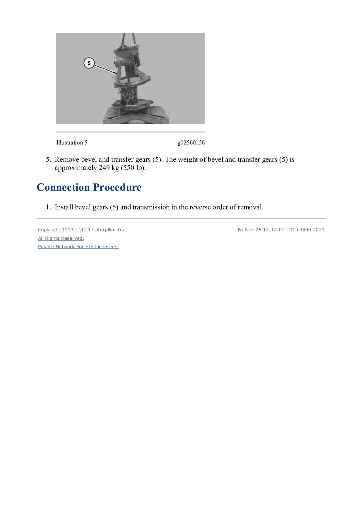
The weight of bevel and transfer gears (5) is approximately 249 kg (550 lb). Connection Procedure 1. Install bevel gears (5) and transmission in the reverse order of removal. Copyright 1993 - 2021 Caterpillar Inc. All Rights Reserved. Private Network For SIS Licensees. Fri Nov 26 12:14:02 UTC+0800 2021
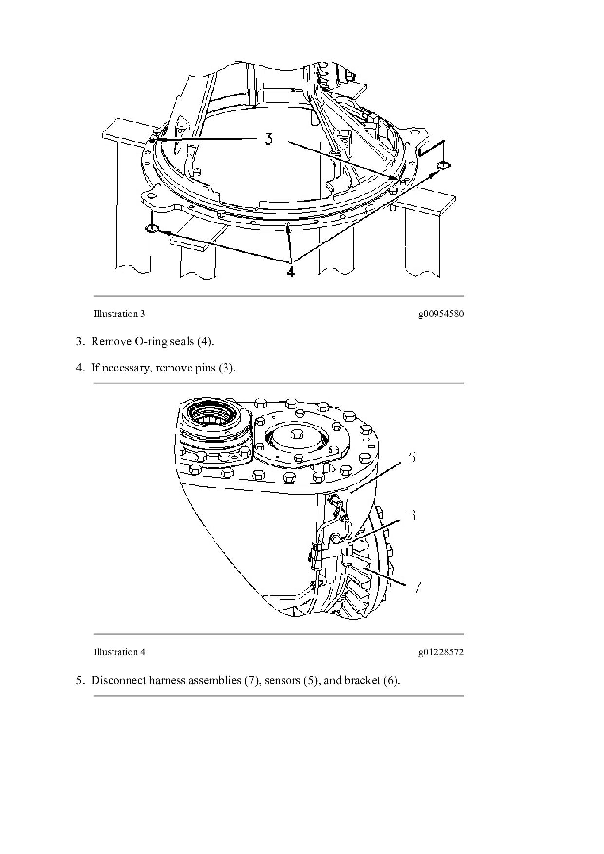
TRACK-TYPE TRACTOR SGG Configuration: D6N XL, LGP TRACK-TYPE TRACTOR SGG00001-UP (MACHINE) POWERED BY C7.1 Engine Disassembly and Assembly D6N Track-Type Tractor Power Train Media Number -UENR4080-03 Publication Date -01/09/2015 Date Updated -31/07/2018 i04670350 Bevel and Transfer Gears - Disassemble SMCS - 3011-015 Disassembly Procedure Table 1 Required Tools Tool Part Number Part Description Qty A 1P-2420 Transmission Repair Stand 1 B 5F-7343 Bearing Puller Gp 1 C 8T-2839 Spanner Wrench 1 Start By: a. Separate the transmission and bevel gears. Refer to Disassembly and Assembly, "Transmission and Bevel Gears - Separate".
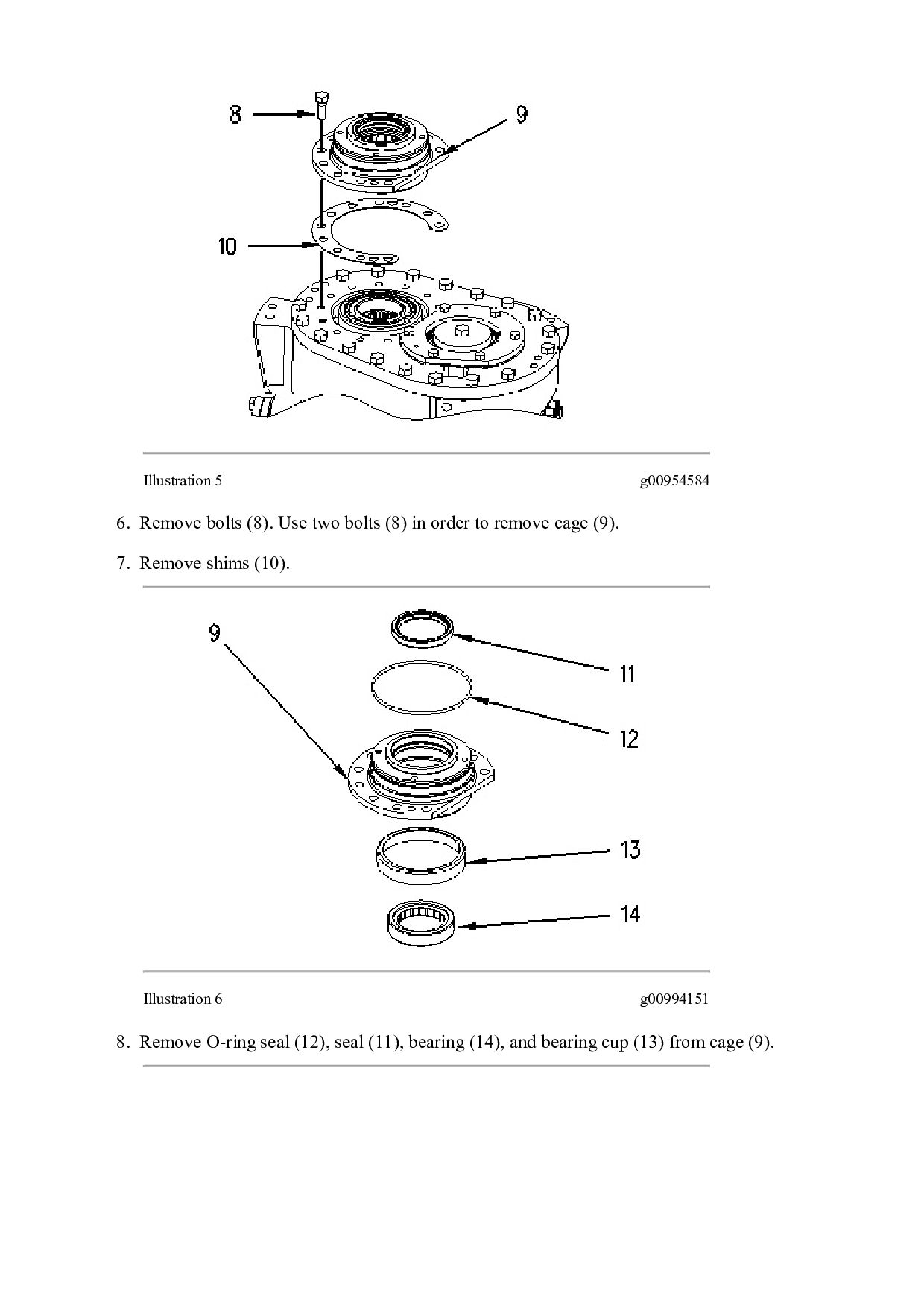
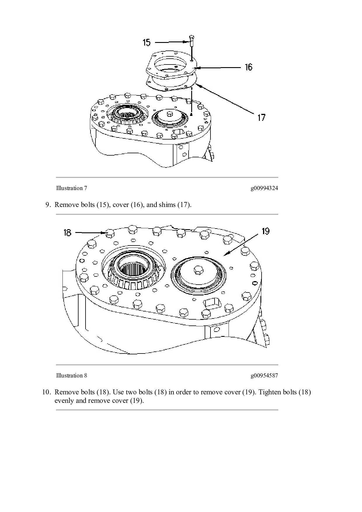
(8) in order to remove cage (9). 7. Remove shims (10). Illustration 6 g00994151 8. Remove O-ring seal (12), seal (11), bearing (14), and bearing cup (13) from cage (9).
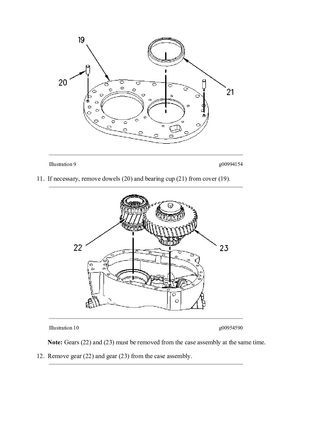
shims (17). Illustration 8 g00954587 10. Remove bolts (18). Use two bolts (18) in order to remove cover (19). Tighten bolts (18) evenly and remove cover (19).
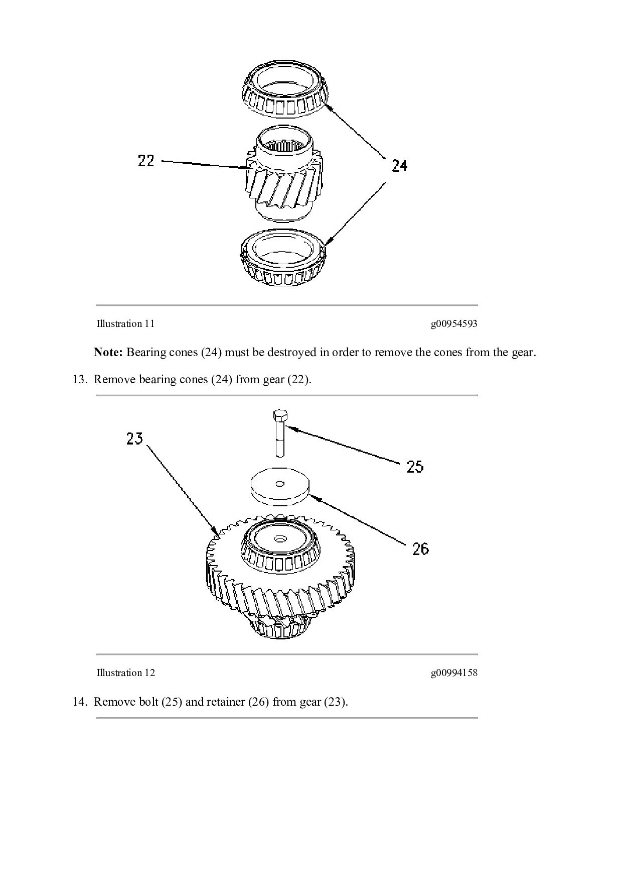
bearing cup (21) from cover (19). Illustration 10 g00954590 Note: Gears (22) and (23) must be removed from the case assembly at the same time. 12. Remove gear (22) and gear (23) from the case assembly.
in order to remove the cones from the gear. 13. Remove bearing cones (24) from gear (22). Illustration 12 g00994158 14. Remove bolt (25) and retainer (26) from gear (23).
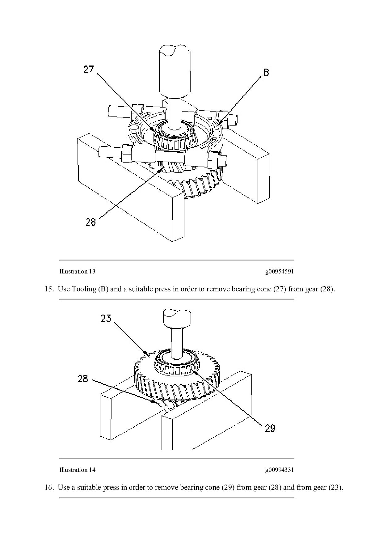
press in order to remove bearing cone (27) from gear (28). Illustration 14 g00994331 16. Use a suitable press in order to remove bearing cone (29) from gear (28) and from gear (23).
Then Get COMPLETE MANUAL. NO WAITING NOTE: If there is no response to click on the link above, please download the PDF document first and then click on it.
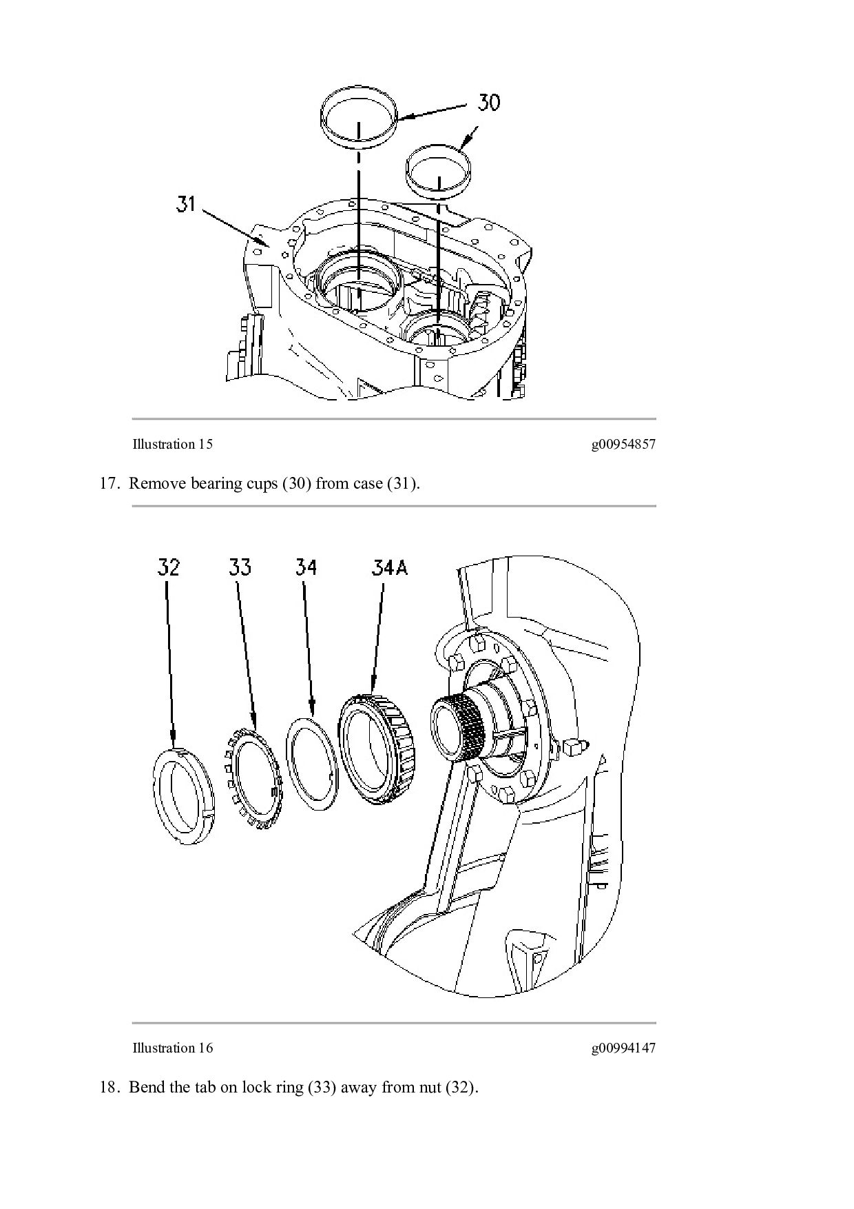
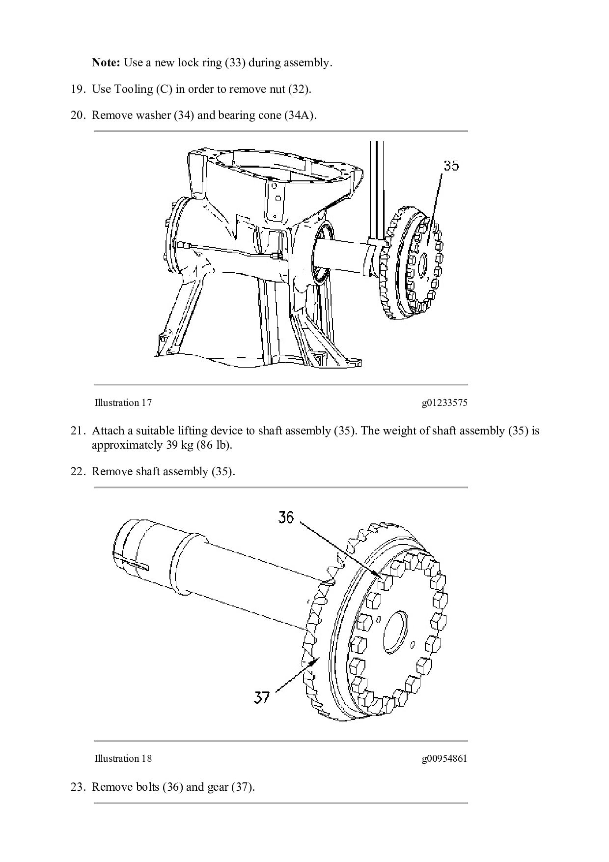
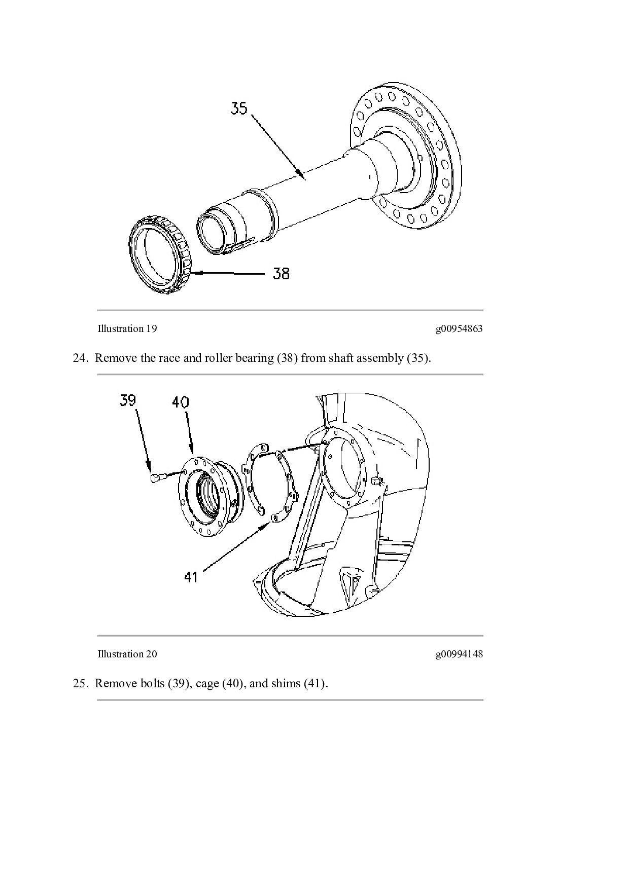
Use Tooling (C) in order to remove nut (32). 20. Remove washer (34) and bearing cone (34A). Illustration 17 g01233575 21. Attach a suitable lifting device to shaft assembly (35). The weight of shaft assembly (35) is approximately 39 kg (86 lb). 22. Remove shaft assembly (35). Illustration 18 g00954861 23. Remove bolts (36) and gear (37).

 Your Podcast. Everywhere. Effortlessly.


 dcrfwdcnvk
 tmiket
 apolaine
 reverentgeek
 marktimemedia
 baasie
 inesmontani
 addyosmani
 aleyda
 kneath
 twada
twada
 mayatellez
 swwweet