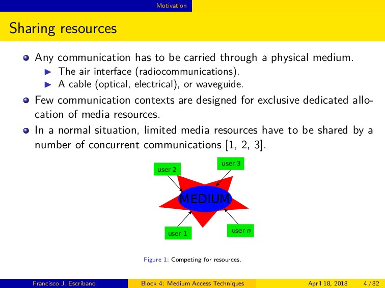
a physical medium. ◮ The air interface (radiocommunications). ◮ A cable (optical, electrical), or waveguide. Few communication contexts are designed for exclusive dedicated allo- cation of media resources. In a normal situation, limited media resources have to be shared by a number of concurrent communications [1, 2, 3]. MEDIUM user 1 user 2 user 3 user n Figure 1: Competing for resources. Francisco J. Escribano Block 4: Medium Access Techniques April 18, 2018 4 / 82
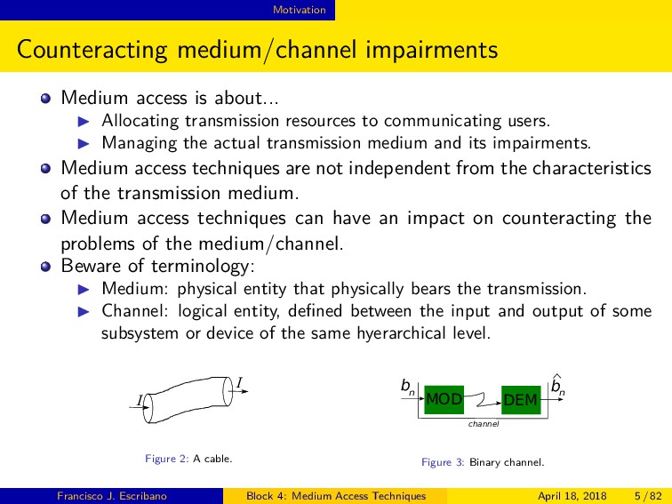
transmission resources to communicating users. ◮ Managing the actual transmission medium and its impairments. Medium access techniques are not independent from the characteristics of the transmission medium. Medium access techniques can have an impact on counteracting the problems of the medium/channel. Beware of terminology: ◮ Medium: physical entity that physically bears the transmission. ◮ Channel: logical entity, defined between the input and output of some subsystem or device of the same hyerarchical level. I I Figure 2: A cable. MOD DEM b n b n channel Figure 3: Binary channel. Francisco J. Escribano Block 4: Medium Access Techniques April 18, 2018 5 / 82
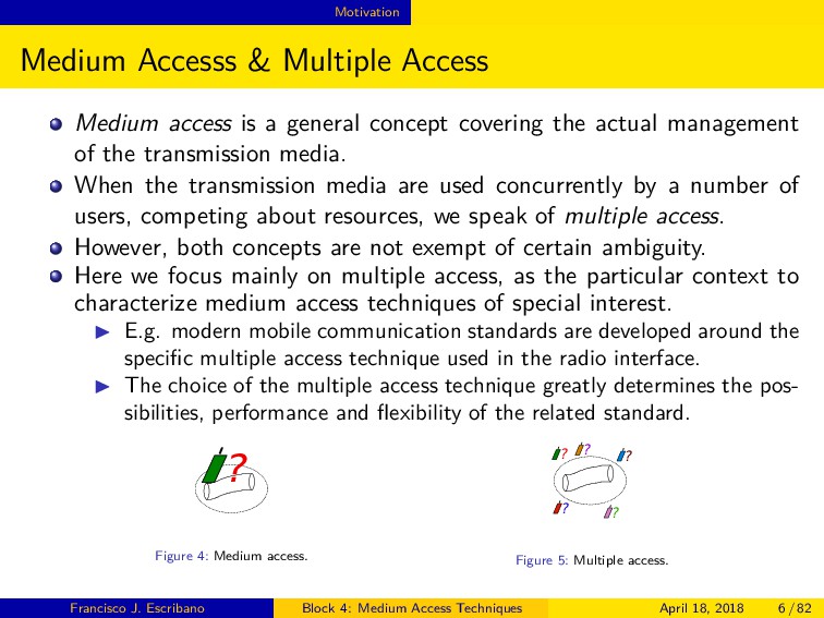
general concept covering the actual management of the transmission media. When the transmission media are used concurrently by a number of users, competing about resources, we speak of multiple access. However, both concepts are not exempt of certain ambiguity. Here we focus mainly on multiple access, as the particular context to characterize medium access techniques of special interest. ◮ E.g. modern mobile communication standards are developed around the specific multiple access technique used in the radio interface. ◮ The choice of the multiple access technique greatly determines the pos- sibilities, performance and flexibility of the related standard. ? Figure 4: Medium access. ? ? ? ? ? Figure 5: Multiple access. Francisco J. Escribano Block 4: Medium Access Techniques April 18, 2018 6 / 82
access and multiplexing are related con- cepts. Both can be grouped as medium access techniques. ◮ They also offer some degree of ambiguity and even confusion. Multiple access: ◮ The access to the resources is performed from multiple points. ◮ Each user meets the other ones directly in the medium. Multiplexing: ◮ A centralized entity handles the communications from different users. ◮ These communications are organized into a frame by said entity. ◮ Users meet at a higher hyerarchical level than the medium. uplink downlink TDMA TDM Figure 6: Multiple access vs multiplexing in a mobile context. Francisco J. Escribano Block 4: Medium Access Techniques April 18, 2018 7 / 82
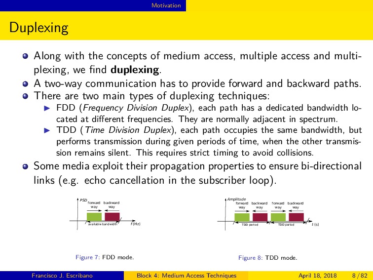
access and multi- plexing, we find duplexing. A two-way communication has to provide forward and backward paths. There are two main types of duplexing techniques: ◮ FDD (Frequency Division Duplex), each path has a dedicated bandwidth lo- cated at different frequencies. They are normally adjacent in spectrum. ◮ TDD (Time Division Duplex), each path occupies the same bandwidth, but performs transmission during given periods of time, when the other transmis- sion remains silent. This requires strict timing to avoid collisions. Some media exploit their propagation properties to ensure bi-directional links (e.g. echo cancellation in the subscriber loop). f (Hz) PSD available bandwidth forward way backward way Figure 7: FDD mode. t (s) Amplitude TDD period forward way backward way TDD period forward way backward way Figure 8: TDD mode. Francisco J. Escribano Block 4: Medium Access Techniques April 18, 2018 8 / 82
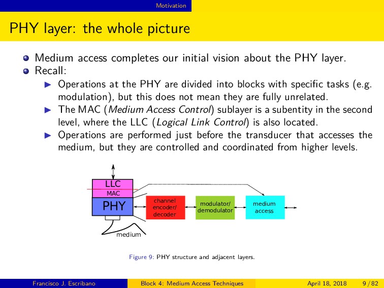
initial vision about the PHY layer. Recall: ◮ Operations at the PHY are divided into blocks with specific tasks (e.g. modulation), but this does not mean they are fully unrelated. ◮ The MAC (Medium Access Control) sublayer is a subentity in the second level, where the LLC (Logical Link Control) is also located. ◮ Operations are performed just before the transducer that accesses the medium, but they are controlled and coordinated from higher levels. PHY LLC MAC medium channel encoder/ decoder modulator/ demodulator medium access Figure 9: PHY structure and adjacent layers. Francisco J. Escribano Block 4: Medium Access Techniques April 18, 2018 9 / 82
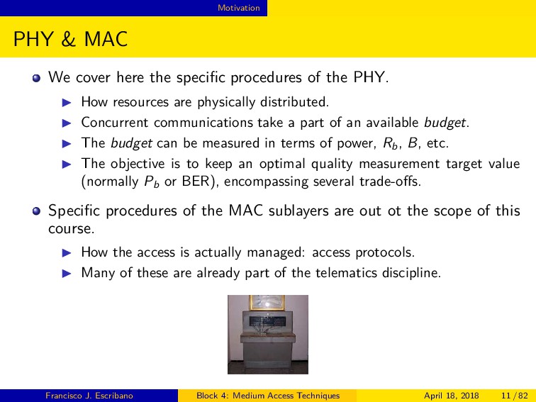
of the PHY. ◮ How resources are physically distributed. ◮ Concurrent communications take a part of an available budget. ◮ The budget can be measured in terms of power, Rb , B, etc. ◮ The objective is to keep an optimal quality measurement target value (normally Pb or BER), encompassing several trade-offs. Specific procedures of the MAC sublayers are out ot the scope of this course. ◮ How the access is actually managed: access protocols. ◮ Many of these are already part of the telematics discipline. Francisco J. Escribano Block 4: Medium Access Techniques April 18, 2018 11 / 82
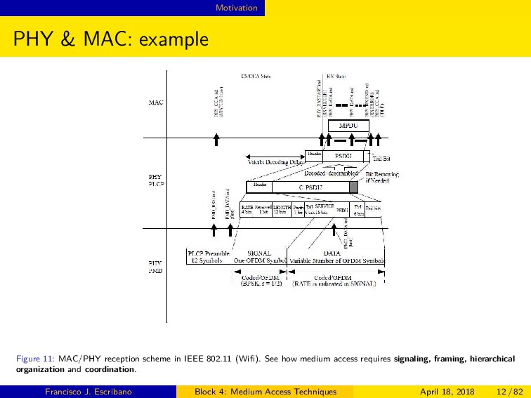
in IEEE 802.11 (Wifi). See how medium access requires signaling, framing, hierarchical organization and coordination. Francisco J. Escribano Block 4: Medium Access Techniques April 18, 2018 12 / 82
shared and managed along specific signal axis. ◮ Frequency. ◮ Time. ◮ Space. ◮ Spreading codes. Though each technique favours a given axis, this does not mean the other axis do not play a role. ◮ Several techniques can take part in a given standard, in a complex way (e.g. Bluetooth). ◮ Some of the mentioned signal axis can be jointly managed in a given access technique (e.g. OFDMA). Francisco J. Escribano Block 4: Medium Access Techniques April 18, 2018 13 / 82
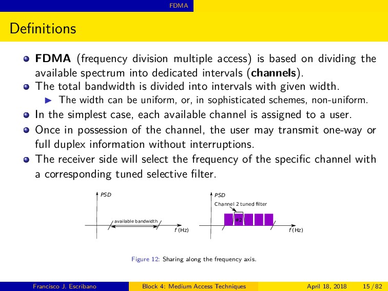
dividing the available spectrum into dedicated intervals (channels). The total bandwidth is divided into intervals with given width. ◮ The width can be uniform, or, in sophisticated schemes, non-uniform. In the simplest case, each available channel is assigned to a user. Once in possession of the channel, the user may transmit one-way or full duplex information without interruptions. The receiver side will select the frequency of the specific channel with a corresponding tuned selective filter. f (Hz) PSD available bandwidth f (Hz) PSD #2 Channel 2 tuned ¡lter Figure 12: Sharing along the frequency axis. Francisco J. Escribano Block 4: Medium Access Techniques April 18, 2018 15 / 82
very carefully to comply with strict spectral masks. ◮ The goal is to minimize Adjacent Channel Interference (ACI). At RX, strict filtering is needed to reject interferences and limit noise. ◮ This requires high quality subsystems at the medium frontend (e.g. RF equipment). Requirements are rendered less stringent by including guard intervals between channels. ◮ This reduces the total available data rate. ◮ Assume a total bandwidth B, N equal channels, a Bg guard interval bandwidth, a modulation (QAM or PSK) with k bits per symbol. B′ is the usable total bandwidth, and Rb the available data rate per channel1. B′ = B − (N − 1)Bg , Rb = kRs = k B′ 2N = k B−(N−1)Bg 2N 1 Beware! The relationship B-Rb has to be managed and calculated taking into account the modulation spectral efficiency and the usage of pulse (spectral) shaping filters -e.g. our known RRC, Root Raised Cosine. Francisco J. Escribano Block 4: Medium Access Techniques April 18, 2018 16 / 82
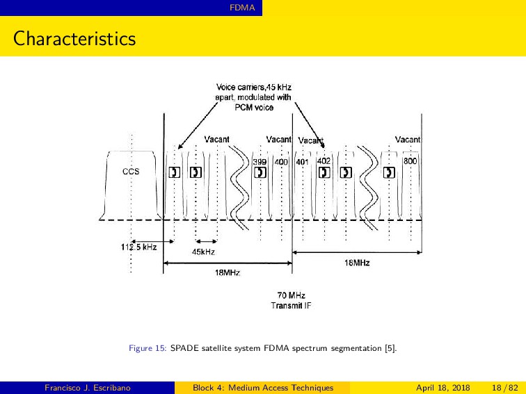
for EU- TELSAT system [4]. f (Hz) PSD B B'/N g ¢£d i¤¥¦£§¢¨ Figure 14: FDMA bandwidth management. Francisco J. Escribano Block 4: Medium Access Techniques April 18, 2018 17 / 82
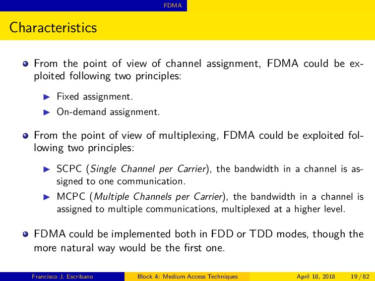
FDMA could be ex- ploited following two principles: ◮ Fixed assignment. ◮ On-demand assignment. From the point of view of multiplexing, FDMA could be exploited fol- lowing two principles: ◮ SCPC (Single Channel per Carrier), the bandwidth in a channel is as- signed to one communication. ◮ MCPC (Multiple Channels per Carrier), the bandwidth in a channel is assigned to multiple communications, multiplexed at a higher level. FDMA could be implemented both in FDD or TDD modes, though the more natural way would be the first one. Francisco J. Escribano Block 4: Medium Access Techniques April 18, 2018 19 / 82
◮ Well known technology with a lot of background. ◮ Hardware is easy to build. ◮ Core network equipments are straightforward to implement. ◮ It does not suffer form the near-far problem of CDMA systems: power control is less critical. ◮ It does not require strict timing, as in TDMA. ◮ Unhindered stream data transfers are possible due to the usage of dedi- cated channels. Francisco J. Escribano Block 4: Medium Access Techniques April 18, 2018 20 / 82
hard to mount. ◮ A lot of equipment may be required for each channel. ◮ It does not handle quite straightforwardly different applications or traffic flows. ◮ It poses difficulties to insert and handle signaling procedures associated to each communication. ◮ It lacks flexibility: difficulties to enhance data quality. ◮ It requires high-performing filters in the radio hardware. Francisco J. Escribano Block 4: Medium Access Techniques April 18, 2018 21 / 82
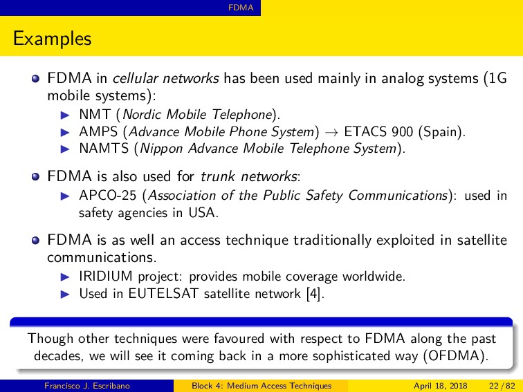
in analog systems (1G mobile systems): ◮ NMT (Nordic Mobile Telephone). ◮ AMPS (Advance Mobile Phone System) → ETACS 900 (Spain). ◮ NAMTS (Nippon Advance Mobile Telephone System). FDMA is also used for trunk networks: ◮ APCO-25 (Association of the Public Safety Communications): used in safety agencies in USA. FDMA is as well an access technique traditionally exploited in satellite communications. ◮ IRIDIUM project: provides mobile coverage worldwide. ◮ Used in EUTELSAT satellite network [4]. Though other techniques were favoured with respect to FDMA along the past decades, we will see it coming back in a more sophisticated way (OFDMA). Francisco J. Escribano Block 4: Medium Access Techniques April 18, 2018 22 / 82
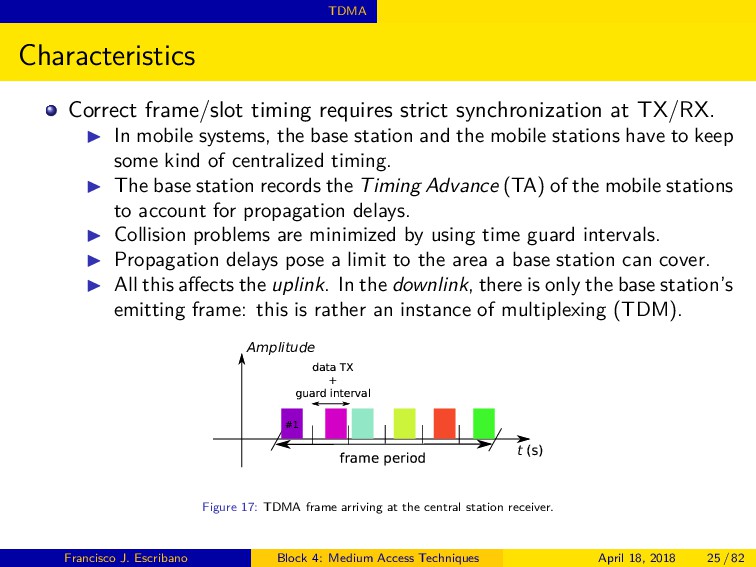
◮ In mobile systems, the base station and the mobile stations have to keep some kind of centralized timing. ◮ The base station records the Timing Advance (TA) of the mobile stations to account for propagation delays. ◮ Collision problems are minimized by using time guard intervals. ◮ Propagation delays pose a limit to the area a base station can cover. ◮ All this affects the uplink. In the downlink, there is only the base station’s emitting frame: this is rather an instance of multiplexing (TDM). Amplitude @ABCD EDAFGH dIPI QR + STIUd VWPXUYIl `a t bcd Figure 17: TDMA frame arriving at the central station receiver. Francisco J. Escribano Block 4: Medium Access Techniques April 18, 2018 25 / 82
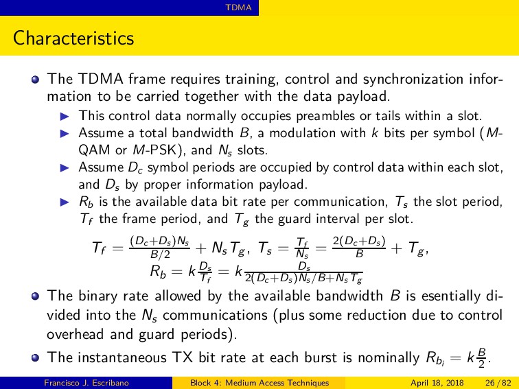
infor- mation to be carried together with the data payload. ◮ This control data normally occupies preambles or tails within a slot. ◮ Assume a total bandwidth B, a modulation with k bits per symbol (M- QAM or M-PSK), and Ns slots. ◮ Assume Dc symbol periods are occupied by control data within each slot, and Ds by proper information payload. ◮ Rb is the available data bit rate per communication, Ts the slot period, Tf the frame period, and Tg the guard interval per slot. Tf = (Dc +Ds )Ns B/2 + Ns Tg , Ts = Tf Ns = 2(Dc +Ds ) B + Tg , Rb = k Ds Tf = k Ds 2(Dc +Ds )Ns /B+Ns Tg The binary rate allowed by the available bandwidth B is esentially di- vided into the Ns communications (plus some reduction due to control overhead and guard periods). The instantaneous TX bit rate at each burst is nominally Rbi = k B 2 . Francisco J. Escribano Block 4: Medium Access Techniques April 18, 2018 26 / 82
there are burst types that carry no information (further decrease in capacity). They nevertheless serve for synchronization purposes. Francisco J. Escribano Block 4: Medium Access Techniques April 18, 2018 27 / 82
bursts RB1 and RB2 further decrease capacity. They are useful to keep Earth stations time aligned. Francisco J. Escribano Block 4: Medium Access Techniques April 18, 2018 28 / 82
number of com- munications) means a corresponding increase in the instantaneous bit rate. ◮ This would lead to increasing the bandwidth used, or the modulation efficiency (which could worsen the Eb /N0 and increase BER). There is a limit in the maximum number of simultaneous communica- tions (Ns ) due to propagation limits. ◮ This could be traded off with the help of the guard period Tg , but at the cost of higher overhead and higher latency. It is also important to consider power limits, and maximum allowed latency. ◮ In practical cellular systems, the limitation for Ns is around 10 per radio- channel (of bandwidth B). A TDMA system can work straightforwardly in TDD or FDD modes. Due to the discrete nature of the TDMA system, it can only be used for digital communications. Francisco J. Escribano Block 4: Medium Access Techniques April 18, 2018 29 / 82
requires a single transceiver for Ns channels. ◮ Higher versatility. The number of time slots assigned to a communication may be adapted to specific requirements. ◮ Easier channel signaling. The control information may be introduced in some bits inside a burst (e.g. a header field), or be carried through some specific dedicated slots. ◮ Higher spectral performance. ◮ Good for handling medium face to high traffic volumes. ◮ It can transmit in a single frequency using TDD in a natural way. This avoids the extensive usage of a number of frequency mixers or medium-specific filters (e.g. RF filters). Francisco J. Escribano Block 4: Medium Access Techniques April 18, 2018 30 / 82
tight time synchronization to avoid collisions. ◮ Inherent frame size limit. If the frame is too big, the terminal has to store a lot of information. ◮ Higher communication delay. Due to the need of information buffering, the communication suffers some delay. ◮ The information must be digital. In case of analog sources, it has to be sampled (quantization noise). ◮ Broadband TDMA communications may be severely affected by fre- quency selective fading. Francisco J. Escribano Block 4: Medium Access Techniques April 18, 2018 31 / 82
◮ GSM worldwide (used along with frequency hopping techniques) [6]. It is also used in trunk networks: ◮ TETRA (Terrestrial Trunked Radio): used in safety agencies mainly, in Europe. Proposed as well in wired standards: ◮ ITU-T G.hn: for high speed LAN over existing home wiring [8]. TDMA constitutes one of the access possibilities for satellite commu- nications: ◮ Used as one of the available implementations of the IRIDIUM satellite mobile system. ◮ Used in the INTELSAT satellite network system [7]. TDMA is being recycled together with FDMA in a joint time-frequency scheme as OFDMA. Francisco J. Escribano Block 4: Medium Access Techniques April 18, 2018 32 / 82
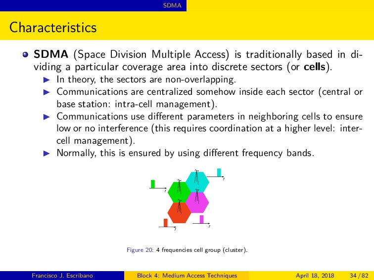
in di- viding a particular coverage area into discrete sectors (or cells). ◮ In theory, the sectors are non-overlapping. ◮ Communications are centralized somehow inside each sector (central or base station: intra-cell management). ◮ Communications use different parameters in neighboring cells to ensure low or no interference (this requires coordination at a higher level: inter- cell management). ◮ Normally, this is ensured by using different frequency bands. f f f f Figure 20: 4 frequencies cell group (cluster). Francisco J. Escribano Block 4: Medium Access Techniques April 18, 2018 34 / 82
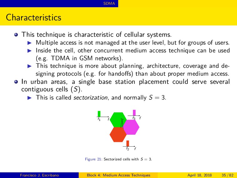
Multiple access is not managed at the user level, but for groups of users. ◮ Inside the cell, other concurrent medium access technique can be used (e.g. TDMA in GSM networks). ◮ This technique is more about planning, architecture, coverage and de- signing protocols (e.g. for handoffs) than about proper medium access. In urban areas, a single base station placement could serve several contiguous cells (S). ◮ This is called sectorization, and normally S = 3. f f f f1 f2 f3 Figure 21: Sectorized cells with S = 3. Francisco J. Escribano Block 4: Medium Access Techniques April 18, 2018 35 / 82
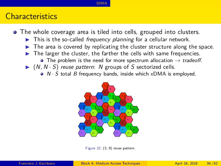
grouped into clusters. ◮ This is the so-called frequency planning for a cellular network. ◮ The area is covered by replicating the cluster structure along the space. ◮ The larger the cluster, the farther the cells with same frequencies. The problem is the need for more spectrum allocation → tradeoff. ◮ (N, N · S) reuse pattern: N groups of S sectorized cells. N · S total B frequency bands, inside which xDMA is employed. A1 A2 A3 B1 B2 B3 C1 C2 C3 A1 A2 A3 B1 B2 B3 C1 C2 C3 A1 A2 A3 B1 B2 B3 C1 C2 C3 A1 A2 A3 B1 B2 B3 C1 C2 C3 A1 A2 A3 B1 B2 B3 C1 C2 C3 A1 A2 A3 B1 B2 B3 C1 C2 C3 Figure 22: (3, 9) reuse pattern. Francisco J. Escribano Block 4: Medium Access Techniques April 18, 2018 36 / 82
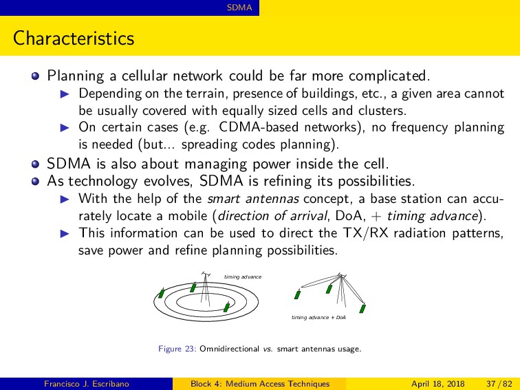
complicated. ◮ Depending on the terrain, presence of buildings, etc., a given area cannot be usually covered with equally sized cells and clusters. ◮ On certain cases (e.g. CDMA-based networks), no frequency planning is needed (but... spreading codes planning). SDMA is also about managing power inside the cell. As technology evolves, SDMA is refining its possibilities. ◮ With the help of the smart antennas concept, a base station can accu- rately locate a mobile (direction of arrival, DoA, + timing advance). ◮ This information can be used to direct the TX/RX radiation patterns, save power and refine planning possibilities. timing advance timing advance + DoA Figure 23: Omnidirectional vs. smart antennas usage. Francisco J. Escribano Block 4: Medium Access Techniques April 18, 2018 37 / 82
http://www.radiocomms.com.au). Things are getting more complicated from the point of view of managing SDMA coverage: overlapping and unplanned deployments. ◮ Communication coverage is increasingly being provided at different scales, with different technologies (LTE, WiFi, WiMax...): Small Cells concept. ◮ The coordination of the different cell sizes and technologies gives rise to the HetNet (Heterogeneous Network) concept. Francisco J. Escribano Block 4: Medium Access Techniques April 18, 2018 38 / 82
It is used along with TDMA and frequency planning in GSM (2G mobile standard). ◮ It is used along with CDMA (and no frequency planning) in UMTS (3G mobile standard). ◮ It is used along with OFDMA and frequency planning in LTE (4G mobile standard). Planning in LTE is nevertheless far more complex than in GSM. In collaboration with the smart antennas concept, SDMA is also used in satellite networks (e.g. INTELSAT IV-A). ◮ With the help of dual-beam receive antenna, it can provide coverage simultaneously to two different Earth regions. The related concept of SDM (Spatial Division Multiplexing) is used in cabled systems. ◮ The space multiplexing concept translates normally into using different cables for different communications. Francisco J. Escribano Block 4: Medium Access Techniques April 18, 2018 39 / 82
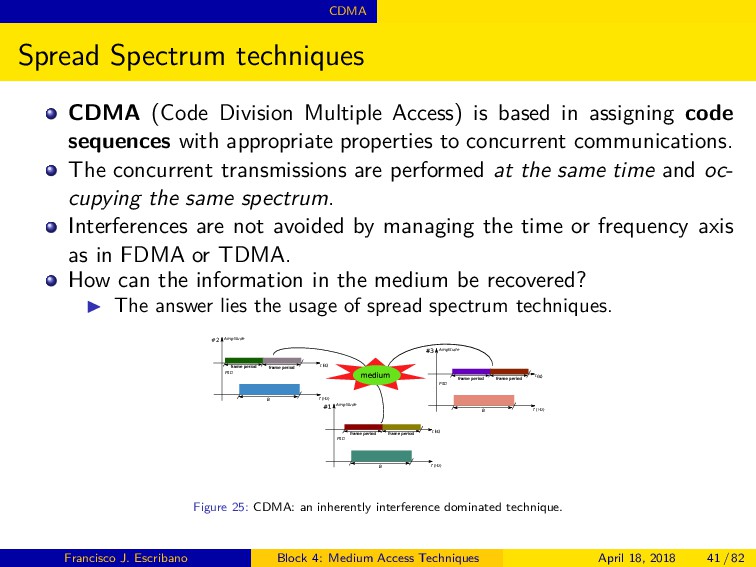
based in assigning code sequences with appropriate properties to concurrent communications. The concurrent transmissions are performed at the same time and oc- cupying the same spectrum. Interferences are not avoided by managing the time or frequency axis as in FDMA or TDMA. How can the information in the medium be recovered? ◮ The answer lies the usage of spread spectrum techniques. f (Hz) Amplitude efghipifqrs efghipifqrs t tuv PSD B wx f (Hz) Amplitude efghipifqrs efghipifqrs t tuv PSD B #2 f (Hz) Amplitude efghipifqrs efghipifqrs t tuv PSD B wy Figure 25: CDMA: an inherently interference dominated technique. Francisco J. Escribano Block 4: Medium Access Techniques April 18, 2018 41 / 82
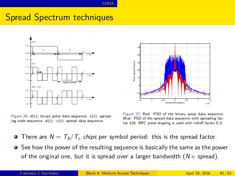
Tb Tb Tc sequence period +A +1 +A −A −1 −A d(t) c(t) d(t) · c(t) Figure 26: d(t): binary polar data sequence. c(t): spread- ing code sequence. d(t) · c(t): spread data sequence. −1.5 −1 −0.5 0 0.5 1 1.5 x 10⁶ −10 0 10 20 30 40 50 Normalized frequency Power Spectral Density Figure 27: Red: PSD of the binary polar data sequence. Blue: PSD of the spread data sequence with spreading fac- tor 128. RRC pulse shaping is used with rolloff factor 0.5. There are N = Tb /Tc chips per symbol period: this is the spread factor. See how the power of the resulting sequence is basically the same as the power of the original one, but it is spread over a larger bandwidth (N× spread). Francisco J. Escribano Block 4: Medium Access Techniques April 18, 2018 42 / 82
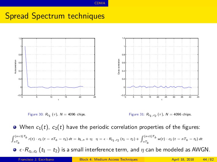
sequences {ci (t)}M i=1 to be useful, they have to meet certain properties: ◮ Rci (τ) ≈ δ (τ). ◮ Rci ,cj (τ) ≈ 0, i = j. ◮ They have to look like noise (pseudorandom or pseudonoise sequences). A CDMA system uses a set of such sequences. ◮ Each concurrent communication is assigned a sequence from the set. ◮ On reception, the rest of concurrent communications are small contri- butions to the received noise. Unless codes are truly orthogonal and they add synchronously in a frame. N defines the so-called processing gain, PG = 10 log10 (N). ◮ The larger N, the higher the bandwidth required, and the lower the power spectral density per communication. ◮ PG is a measurement of the improvement made in Eb /N0 wrt Ec /N0 : the correlator recovers the signal, and filters the noise. ◮ PG is as well a measurement of the resistance to interferences and jam- ming. Francisco J. Escribano Block 4: Medium Access Techniques April 18, 2018 45 / 82
instance of direct-sequence (DS) spread spectrum. ◮ It can be straightforwardly applied to any kind of digital modulation. Managing the frequency axis: frequency-hopping (FH) spread spectrum. ◮ The symbols are transmitted by hopping along a set of frequency slots {∆fi} over the available bandwidth B. ◮ Several hops per symbol period Ts : fast hopping. ◮ Several symbols per hop: slow hopping. Managing the time axis: time-hopping (TH) spread spectrum. ◮ The symbols are transmitted by hopping along a set of time slots {∆ti } at each frame period TF . In FH and TH, the spreading sequence determines a pseudorandom hopping pattern. f (Hz) PSD fi fj Figure 32: FH scheme. t (s) Amplitude frame period ti tj Figure 33: TH scheme. Francisco J. Escribano Block 4: Medium Access Techniques April 18, 2018 46 / 82
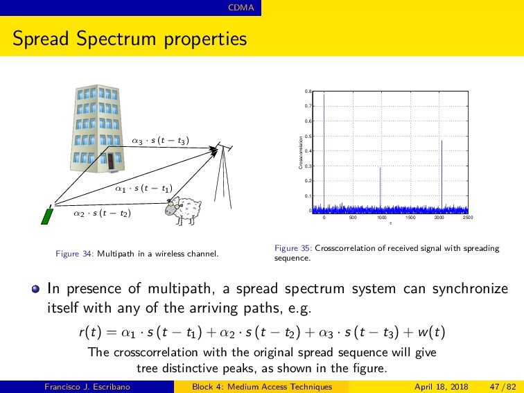
α2 · s (t − t2) α3 · s (t − t3) Figure 34: Multipath in a wireless channel. 0 500 1000 1500 2000 2500 0 0.1 0.2 0.3 0.4 0.5 0.6 0.7 0.8 τ Crosscorrelation Figure 35: Crosscorrelation of received signal with spreading sequence. In presence of multipath, a spread spectrum system can synchronize itself with any of the arriving paths, e.g. r(t) = α1 · s (t − t1 ) + α2 · s (t − t2 ) + α3 · s (t − t3 ) + w(t) The crosscorrelation with the original spread sequence will give tree distinctive peaks, as shown in the figure. Francisco J. Escribano Block 4: Medium Access Techniques April 18, 2018 47 / 82
individuate and combine up to m paths. ◮ It can counteract multipath effects on the received signal. ◮ Delays τ1, τ2, ... τm are calculated with the help of the correlation properties seen. ◮ There are two steps: acquisiton and tracking. ◮ The amplitude and phase compensations, αi , φi , allow constructive combination (e.g. following a maximal ratio combining criterion, which maximizes total SNR). c(t) c(t) c(t) r(t) Σ τ1 τ2 τm α1, φ1 α2, φ2 αm, φm Tb 0 (·)dt Tb 0 (·)dt Tb 0 (·)dt Figure 36: Rake receiver. Francisco J. Escribano Block 4: Medium Access Techniques April 18, 2018 48 / 82
suitable spreading codes from a given set to concurrent communications. ◮ All the communication frames share the same spectrum and operate at the same time, interfering each other. The spreading factor can be different for different communications. ◮ This allows the assignment of different data rates / quality for different users. CDMA permits the random and asynchronous usage of the medium. ◮ There is no need for a global synchronization system. ◮ But, if all the frames are managed synchronously, it is possible to use orthogonal spreading codes (e.g. OVSF2 codes in UMTS donwlink.) In a cellular system with SDMA, CDMA does not require frequency planning. ◮ Neighboring cells use different sets of codes. 2 Orthogonal Variable Spreading Factor Francisco J. Escribano Block 4: Medium Access Techniques April 18, 2018 49 / 82
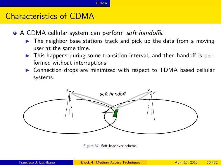
soft handoffs. ◮ The neighbor base stations track and pick up the data from a moving user at the same time. ◮ This happens during some transition interval, and then handoff is per- formed without interruptions. ◮ Connection drops are minimized with respect to TDMA based cellular systems. soft hando Figure 37: Soft handover scheme. Francisco J. Escribano Block 4: Medium Access Techniques April 18, 2018 50 / 82
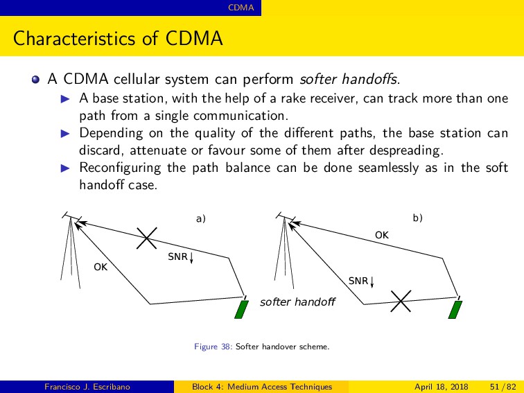
softer handoffs. ◮ A base station, with the help of a rake receiver, can track more than one path from a single communication. ◮ Depending on the quality of the different paths, the base station can discard, attenuate or favour some of them after despreading. ◮ Reconfiguring the path balance can be done seamlessly as in the soft handoff case. softer handoe hj hj a) b) kln kln Figure 38: Softer handover scheme. Francisco J. Escribano Block 4: Medium Access Techniques April 18, 2018 51 / 82
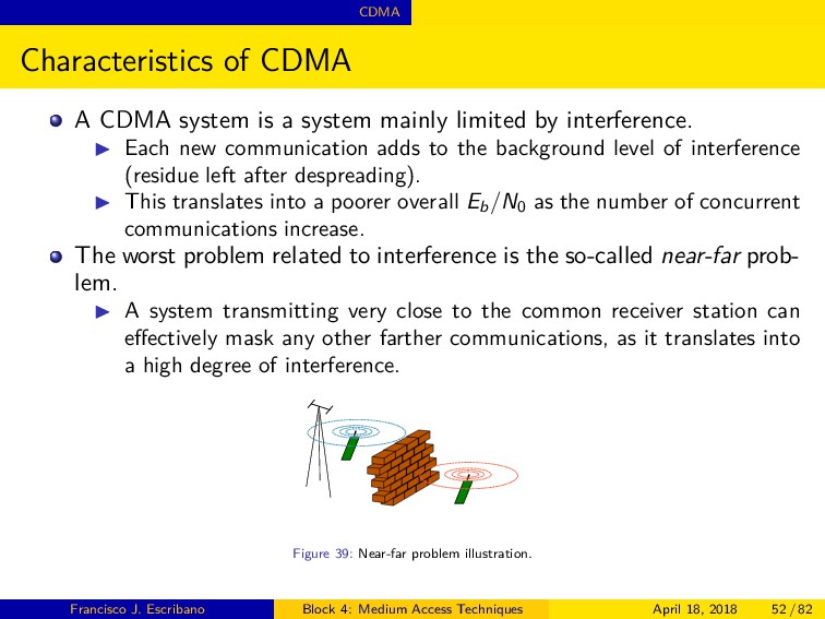
mainly limited by interference. ◮ Each new communication adds to the background level of interference (residue left after despreading). ◮ This translates into a poorer overall Eb /N0 as the number of concurrent communications increase. The worst problem related to interference is the so-called near-far prob- lem. ◮ A system transmitting very close to the common receiver station can effectively mask any other farther communications, as it translates into a high degree of interference. Figure 39: Near-far problem illustration. Francisco J. Escribano Block 4: Medium Access Techniques April 18, 2018 52 / 82
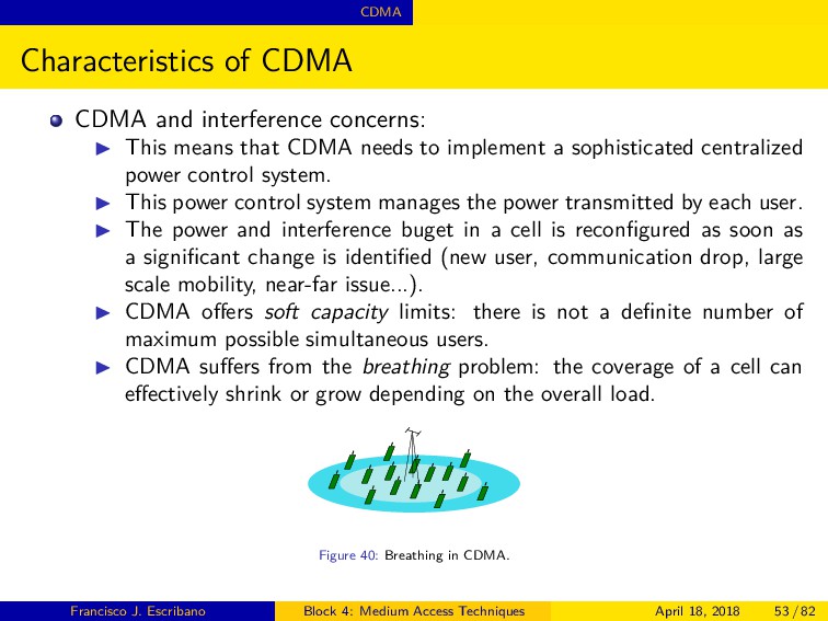
means that CDMA needs to implement a sophisticated centralized power control system. ◮ This power control system manages the power transmitted by each user. ◮ The power and interference buget in a cell is reconfigured as soon as a significant change is identified (new user, communication drop, large scale mobility, near-far issue...). ◮ CDMA offers soft capacity limits: there is not a definite number of maximum possible simultaneous users. ◮ CDMA suffers from the breathing problem: the coverage of a cell can effectively shrink or grow depending on the overall load. Figure 40: Breathing in CDMA. Francisco J. Escribano Block 4: Medium Access Techniques April 18, 2018 53 / 82
at least a SNR after despreading of (Eb /N0 ) min . The power received is Pk for k-th communication, for a total L active communica- tions. The scheme uses BPSK modulation and DSSS. The chip rate is fixed for the system, Rch , while the service offers a Rb data rate, with a so-called activity factor3 0 < ν ≤ 1: Rch / (Rb · ν) is the effective PG. The total interference + noise affecting the communication at the receiver is IT . Eb N0 min ≤ Pk ·Rch Rb·ν·(IT −Pk ) , Lk = Pk IT NFR = 1 − L k=1 Lk −1 Lk is the load factor, and NFR, the total near-far ratio, which measures the quality of the service inside the cell. An NFR of 5dB is the upper practical limit. This kind of calculation has to be extended over all the possible services, and for the uplink and downlink separately. The final result allows the adjustement of the power and interference bugdet of the cell. 3 E.g. 1 for data, 0.67 for voice. Francisco J. Escribano Block 4: Medium Access Techniques April 18, 2018 54 / 82
N0 Dl Eb N0 type (kpbs) kind (Km/h) (dB) (dB) Voice 8 Interior A 3 4.8 6.7 Voice 8 Pedestrian A 3 4.8 6.8 RT Data 64 Interior A 3 2.3 1.9 RT Data 64 Pedestrian A 3 2.4 1.9 RT Data 64 Vehicular A 120 3.8 3.7 NRT Data 144 Vehicular A 120 3.0 2.9 NRT Data 384 Pedestrian A 3 0.4 0.1 Table 1: Example of quality parameters for different services in UMTS [9]. RT: real time; NRT: non-real time. Chip rate in UMTS is Rch = 3.84 Mcps. Calculations should also take into account modulation effiency and channel coding rate. The real scope is providing a limited BER for each service/user. All these principles, plus traffic requirements, lead to CDMA network planning. Francisco J. Escribano Block 4: Medium Access Techniques April 18, 2018 55 / 82
can accommodate more users per MHz of bandwidth than any other technology, excepting OFDM. ◮ Has no built-in limit to the number of concurrent users (soft capacity). ◮ Consumes less power: able to produce a communication of reasonable quality with lower signal levels. ◮ Soft hand-off reduces the likelihood of dropped calls. ◮ High flexibility to accommodate different services (different spreading factors). ◮ It can resist narrowband jammers (interferers). ◮ It can counteract multipath (rake receiver) and better resist frequency- selective fading. Francisco J. Escribano Block 4: Medium Access Techniques April 18, 2018 56 / 82
of spread spectrum: breathing, near-far problem. ◮ Because CDMA towers interfere with themselves, they are normally in- stalled on much shorter towers. ◮ CDMA may not perform well in rugged terrain due to the lower tower height. ◮ Strict need of a centralized and burdensome power control system. ◮ Difficult-to-manage coverage, quality, power, interference tradeoffs. A CDMA-based system offers high degree of flexibility, but at the cost of more complicated hardware, methods and protocols. Francisco J. Escribano Block 4: Medium Access Techniques April 18, 2018 57 / 82
in DS mode: ◮ IS-95 (also known as CdmaOne), 2G American standard. ◮ UMTS (Universal Mobile Telecommunications System), 3G standard: it employs WCDMA (Wideband-CDMA) [9]. ◮ Cdma2000, 3G American standard [10]. Used as well in wired standards: ◮ MC-CDMA (Multi-Carrier CDMA), an alternative to known ADSL stan- dards; it is in fact a variant of OFDM, combined with FH spread spectrum [11]. CDMA constitutes one of the access possibilities for satellite commu- nications: ◮ Used in the Globalstar satellite phone network [12]. CDMA as a standalone access technique is not so important nowadays, but spread spectrum is extensively exploited in many state-of-the-art developments. Francisco J. Escribano Block 4: Medium Access Techniques April 18, 2018 58 / 82
understood under the concept of Multicarrier Modulation. ◮ We have considered FDMA/FDM, TDMA/TDM and CDMA as tech- niques where a variety of users share the resources of the transmitting medium. Each of these schemes, from the point of view of the xDMA user, resorts so Single-Carried Modulation. ◮ The user data modulates a given carrier, located at a specific frequency, following the rules of the xDMA scheme applied. We may think of driving a set of (sub)carriers, occupying a contiguous spectrum, with a single user data, multiplying the resources allocated for the transmission. ◮ This may be seen as an instance of multiplexing (FDM). ◮ Signal / spectrum management has to be done in such a way as to avoid interferences among subcarriers. ◮ We have to guarantee unhindered data recovery at the receiver. Francisco J. Escribano Block 4: Medium Access Techniques April 18, 2018 60 / 82
Multi- plexing), a multicarrier modulation scheme. OFDM builds a signal by plugging a block of modulated symbols into different subcarriers by means of the inverse discrete Fourier transform (IDFT) [13]. ◮ Let’s assume a sequence of baseband modulated symbols {Xn } (ASK, PSK, QAM, etc.), where Xn = XI n + j · XQ n . ◮ We perform an IDFT of order N over each block of N modulated sym- bols. vk = 1 √ N N−1 n=0 Xnej 2πkn N , k = 0, · · · , N − 1 The new sequence vk can be seen in the spectral domain as comprising a group of N orthogonal subcarriers, ej2πkn/N . ◮ Orthogonality: N−1 n=0 ej2πkn/N e−j2πmn/N = 0 for k = m. The n-th subcarrier ej2πkn/N delivers the modulated data given by the n-th symbol Xn along a duration k of N samples (subcarrier mapping). Francisco J. Escribano Block 4: Medium Access Techniques April 18, 2018 61 / 82
symbols OFDM symbols I channel Q channel output frame - cos (2πfc t) sin (2πfc t) Σ v(t) X0 X1 X2 XN−1 v0 v1 v2 vN−1 Figure 41: OFDM transmitter. The modulated data is blockwise processed and mapped into subcarriers, the OFDM symbols are converted into an analog signal v(t) with symbol period T, and trans- ferred to a carrier frequency fc . v(t) = 1 √ T N−1 n=0 Xnej 2πnt T , 0 ≤ t < T The subcarrier spacing 1/T guarantees the orthogonality. As a difference with FSK, no bank of oscillators is needed. Francisco J. Escribano Block 4: Medium Access Techniques April 18, 2018 62 / 82
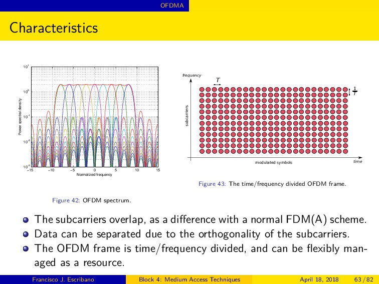
10−2 10−1 100 101 Normalized frequency Power spectral density Figure 42: OFDM spectrum. time frequency subcarriers modulated symbols T 1 T Figure 43: The time/frequency divided OFDM frame. The subcarriers overlap, as a difference with a normal FDM(A) scheme. Data can be separated due to the orthogonality of the subcarriers. The OFDM frame is time/frequency divided, and can be flexibly man- aged as a resource. Francisco J. Escribano Block 4: Medium Access Techniques April 18, 2018 63 / 82
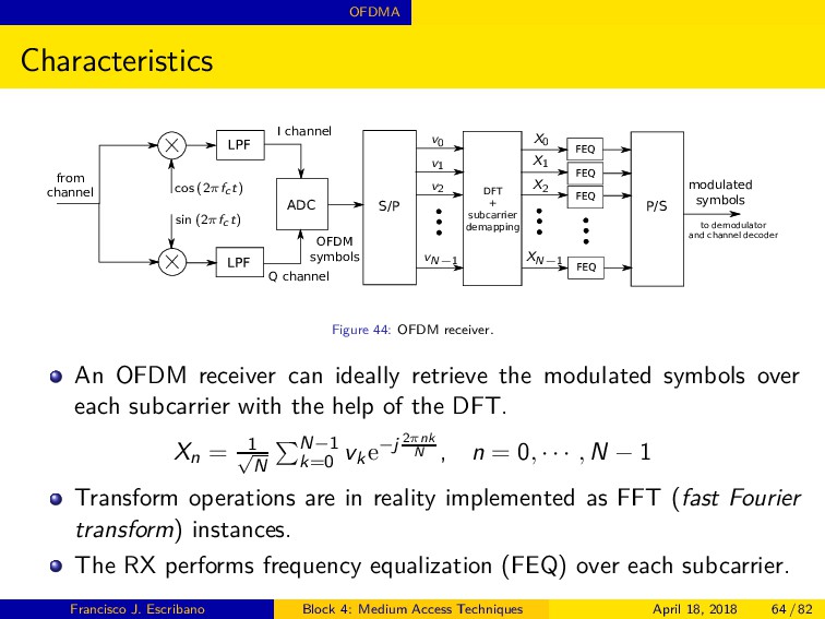
symbols OFDM symbols I channel Q channel opq opq ruv ruv ruv ruv to demodulator and channel decoder from channel cos (2πfc t) sin (2πfc t) X0 X1 X2 XN−1 v0 v1 v2 vN−1 Figure 44: OFDM receiver. An OFDM receiver can ideally retrieve the modulated symbols over each subcarrier with the help of the DFT. Xn = 1 √ N N−1 k=0 vke−j 2πnk N , n = 0, · · · , N − 1 Transform operations are in reality implemented as FFT (fast Fourier transform) instances. The RX performs frequency equalization (FEQ) over each subcarrier. Francisco J. Escribano Block 4: Medium Access Techniques April 18, 2018 64 / 82
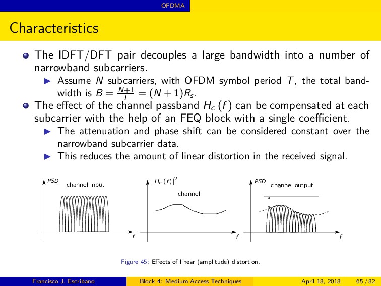
a number of narrowband subcarriers. ◮ Assume N subcarriers, with OFDM symbol period T, the total band- width is B = N+1 T = (N + 1)Rs . The effect of the channel passband Hc (f ) can be compensated at each subcarrier with the help of an FEQ block with a single coefficient. ◮ The attenuation and phase shift can be considered constant over the narrowband subcarrier data. ◮ This reduces the amount of linear distortion in the received signal. PSD PSD channel input channel channel output f f f |Hc (f )|2 Figure 45: Effects of linear (amplitude) distortion. Francisco J. Escribano Block 4: Medium Access Techniques April 18, 2018 65 / 82
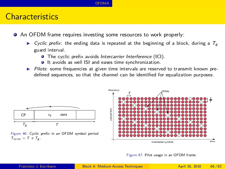
work properly: ◮ Cyclic prefix: the ending data is repeated at the beginning of a block, during a Tg guard interval. The cyclic prefix avoids Intercarrier Interference (ICI). It avoids as well ISI and eases time synchronization. ◮ Pilots: some frequencies at given time intervals are reserved to transmit known pre- defined sequences, so that the channel can be identified for equalization purposes. CP data vk Tg T Figure 46: Cyclic prefix in an OFDM symbol period T sym = T + Tg . time frequency subcarriers modulated symbols Pilots T 1 T Figure 47: Pilot usage in an OFDM frame. Francisco J. Escribano Block 4: Medium Access Techniques April 18, 2018 66 / 82
Assume the channel has taps hc [l], for l = 0, · · · , L−1, for an impulse response of length L. During an OFDM symbol transmission, data is represented by d [m], m = 0, · · · , N +Ng −1, where Ng is the length in samples of the cyclic prefix, and d [m] = v(m+N−Ng ) mod N The convolution r [m] = L−1 l=0 d [m − l]·hc [l], L−1 ≤ m ≤ N+Ng −1, becomes circular convolution if Ng ≥ L, and, under the DFT DFT {r [m]} = Hc [n] · Xn , 0 ≤ m ≤ N − 1 where Hc [n] is the DFT of the channel impulse response. If CP is long enough, it is guaranteed that the channel effect on mod- ulated data Xn can be compensated with a single coefficient. Francisco J. Escribano Block 4: Medium Access Techniques April 18, 2018 67 / 82
scheme. ◮ A given communication can be assigned a number of subcarriers during given symbol intervals. ◮ The frequency hopping scheme fits quite naturally into an OFDM frame. ◮ All this flexibility comes at the cost of more refined protocols and sig- naling overhead. time frequency subcarriers modulated symbols Pilots T 1 T Figure 48: Frequency/symbol assignment along an OFDMA frame. Francisco J. Escribano Block 4: Medium Access Techniques April 18, 2018 68 / 82
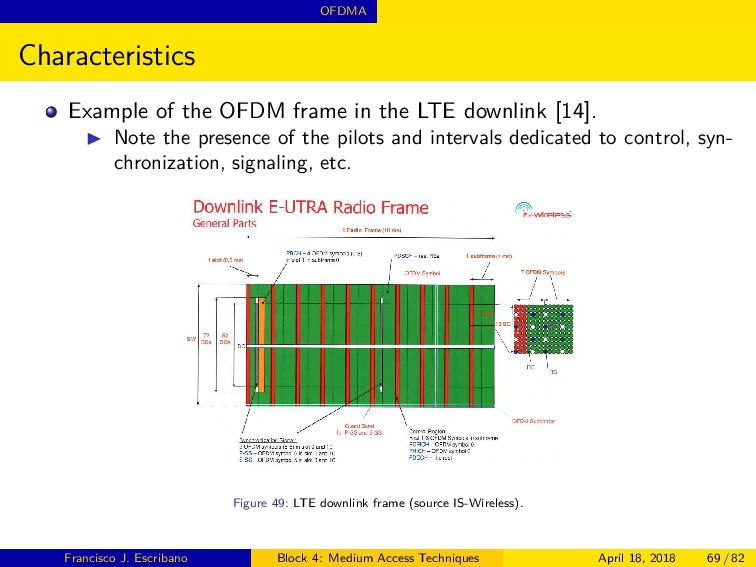
downlink [14]. ◮ Note the presence of the pilots and intervals dedicated to control, syn- chronization, signaling, etc. Figure 49: LTE downlink frame (source IS-Wireless). Francisco J. Escribano Block 4: Medium Access Techniques April 18, 2018 69 / 82
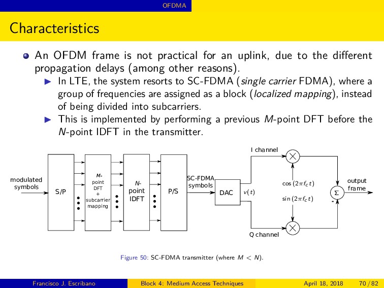
uplink, due to the different propagation delays (among other reasons). ◮ In LTE, the system resorts to SC-FDMA (single carrier FDMA), where a group of frequencies are assigned as a block (localized mapping), instead of being divided into subcarriers. ◮ This is implemented by performing a previous M-point DFT before the N-point IDFT in the transmitter. S/P P/S DAC point DFT + subcarrier mapping modulated symbols SC-FDMA symbols I channel Q channel output frame - point IDFT wx N- cos (2πfc t) sin (2πfc t) Σ v(t) Figure 50: SC-FDMA transmitter (where M < N). Francisco J. Escribano Block 4: Medium Access Techniques April 18, 2018 70 / 82
uplink [14]. ◮ Note the differences with respect to the OFDM downlink frame. ◮ Data have to be time/frequency aligned. Figure 51: LTE uplink frame (source IS-Wireless). Francisco J. Escribano Block 4: Medium Access Techniques April 18, 2018 71 / 82
a cyclic prefix with duration Tg , and N useful subcarriers. The efficiency of the modulation is k bits per symbol. Assume Np pilot frequencies (out of N) reserved each Nd symbol pe- riods. The effective data rate to be shared is: Rs = N T+Tg · Nd −1 Nd + N−Np T+Tg · 1 Nd Rb = k · Rs Note how the usage of the CP and pilot frequencies affect the overall rate. All this have to be taken into account when calculating the effective Eb /N0 and BER. Francisco J. Escribano Block 4: Medium Access Techniques April 18, 2018 72 / 82
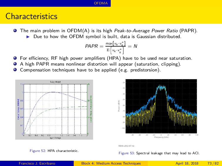
Peak-to-Average Power Ratio (PAPR). ◮ Due to how the OFDM symbol is built, data is Gaussian distributed. PAPR = max[vk ·v∗ k ] E vk ·v∗ k = N For efficiency, RF high power amplifiers (HPA) have to be used near saturation. A high PAPR means nonlinear distortion will appear (saturation, clipping). Compensation techniques have to be applied (e.g. predistorsion). Figure 52: HPA characteristic. Frequency (kHz) Power (dBW) −80 −60 −40 −20 0 20 40 60 80 100 −100 −90 −80 −70 −60 −50 −40 −30 −20 RBW=292.97 Hz Figure 53: Spectral leakage that may lead to ACI. Francisco J. Escribano Block 4: Medium Access Techniques April 18, 2018 73 / 82
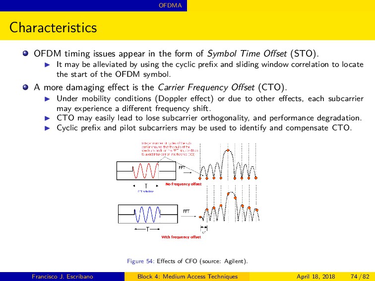
Symbol Time Offset (STO). ◮ It may be alleviated by using the cyclic prefix and sliding window correlation to locate the start of the OFDM symbol. A more damaging effect is the Carrier Frequency Offset (CTO). ◮ Under mobility conditions (Doppler effect) or due to other effects, each subcarrier may experience a different frequency shift. ◮ CTO may easily lead to lose subcarrier orthogonality, and performance degradation. ◮ Cyclic prefix and pilot subcarriers may be used to identify and compensate CTO. Figure 54: Effects of CFO (source: Agilent). Francisco J. Escribano Block 4: Medium Access Techniques April 18, 2018 74 / 82
severe channel conditions without com- plex equalization. ◮ Robust to narrow-band co-channel interference. ◮ Robust to inter-symbol interference and fading caused by multipath prop- agation. ◮ High spectral efficiency. ◮ Efficient implementation (FFTs are highly optimized in hardware). ◮ Low sensitivity to time synchronization errors. ◮ Tuned sub-channel receiver filters are not required (unlike conventional FDMA). ◮ Enables the deployment of single frequency networks for broadcasting. ◮ High flexibility to accomodate different rates/services into subcarriers. Francisco J. Escribano Block 4: Medium Access Techniques April 18, 2018 75 / 82
to manage reception under mobility conditions. ◮ Sensitive to frequency synchronization problems (carrier offset). Dedicated algorithms and extra redundancy are needed to compensate for this, adding to the complexity and the loss of efficiency of the scheme. ◮ Tones on the edges have to be spared to comply with spectral masks. Side lobes do not fall steep enough in standard OFDM. ◮ Inefficient transmitter power consumption. HPA + high PAPR require operation in the linear region. Unavoided nonlinear distortion creates spectral leakages. SC-FDMA solves in part this issue (single carrier scheme!). Francisco J. Escribano Block 4: Medium Access Techniques April 18, 2018 76 / 82
usage. ◮ Digital audio systems EUREKA 147, Digital Radio Mondiale, HD Radio, T-DMB and ISDB-TSB. ◮ The terrestrial digital TV systems DVB-T, DVB-H, T-DMB and ISDB-T. In two-way wireless comms, OFDM is becoming dominant. ◮ Pre-4G and 4G systems: the IEEE 802.16 or WiMax Wireless MAN standard and the 3GPP LTE (Long Term Evolution) standard [14]. ◮ The IEEE 802.20 or Mobile Broadband Wireless Access (MBWA) stan- dard. ◮ IEEE 802.11a and 802.11g Wireless LANs. ◮ The Flash-OFDM cellular system. ◮ Some Ultra wideband (UWB) systems. ◮ Point-to-point (PtP) and point-to-multipoint (PtMP) wireless applica- tions. In cable systems, we can find also important examples. ◮ ADSL and VDSL broadband access via telephone network copper wires. ◮ Power line communications (PLC). Francisco J. Escribano Block 4: Medium Access Techniques April 18, 2018 77 / 82
access domain. ◮ Medium access, multiple access, multiplexing, duplexing. The different methods put the stress over a given signal axis. ◮ Frequency, time, space, code. The classification is not exclusive. ◮ Different methods can be used at the same time (e.g. SDMA and TDMA in GSM). ◮ Putting the stress over one given axis does not imply that the system forgets about the rest. Current trend goes towards the assimilation of different techniques on a single system. ◮ This leads to a progressive increase in control demands and complexity (recall LTE). Medium access is performed at the PHY level, but naturally involves higher communication layers, as it is controlled by the MAC sublayer. Francisco J. Escribano Block 4: Medium Access Techniques April 18, 2018 79 / 82
Digital Communications over Fading Channels. New Jersey: John Wiley & Sons, Inc., 2005. [2] A. Goldsmith, Wireless Communications. New York: Cambridge University Press, 2005. [3] E. Krouk and S. Semenov, Modulation and coding techniques in wireless communications. Chichester: Wiley, 2011. [4] Eutelsat Company Web Site, “SMS QPSK/FDMA System Specification,” EESS 501 G Issue 3. [Online]. Available: http://www.eutelsat.com/files/contributed/satellites/pdf/eess501.pdf [5] A. Khanifar, Satellite Communication Systems. Boca Rat´ on: CRC Press LLC, 2000. [6] 3rd Generation Partnership Project, “Physical layer on the radio path,” Technical Specification Group GSM/EDGE Radio Access Network. [Online]. Available: http://www.3gpp.org/DynaReport/45001.htm [7] A. S. Oei, R. J. Colby, R. Parthasarathy, and A. L. Stimson, “Alignment, testing and maintenance principles in the intelsat tdma/dsi network,” International Journal of Satellite Communications, vol. 3, no. 1-2, pp. 161–166, 1985. [Online]. Available: http://dx.doi.org/10.1002/sat.4600030118 [8] ITU-R.G.9960, “Unified high-speed wireline-based home networking transceivers - System architecture and physical layer spec- ification,” International Telecommunication Union. [Online]. Available: http://www.itu.int/rec/T-REC-G.9960/en [9] 3G TS.25.212 V3.3.0 (2000-06), “Multiplexing and Channel Coding (FDD),” Technical Specification Group Radio Access Network, 3rd Generation Partnership Project. [10] 3GPP2 C.S0002-D Version 1.0, “Physical Layer Standard for cdma2000 Spread Spectrum Systems, Revision D,” Third Generation Partnership Project 2 (3GGP2). [11] K. Fazel and S. Kaiser, Multi-Carrier and Spread Spectrum Systems: From OFDM and MC-CDMA to LTE and WiMAX. New York: John Wiley & Sons, 2008. Francisco J. Escribano Block 4: Medium Access Techniques April 18, 2018 81 / 82
Monte, “The Globalstar cellular satellite system,” Antennas and Propagation, IEEE Transac- tions on, vol. 46, no. 6, pp. 935–942, 1998. [13] Y. S. Cho, J. Kim, W. Y. Yang, and C. G. Kang, MIMO-OFDM Wireless Communications with MATLAB. Singapore: John Wiley & Sons, 2010. [14] 3GPP TS 36.211, “Evolved Universal Terrestrial Radio Access (E-UTRA); Physical channels and modulation,” Technical Specification Group Radio Access Network, 3rd Generation Partnership Project. Francisco J. Escribano Block 4: Medium Access Techniques April 18, 2018 82 / 82
![TDMA Characteristics Figure 18: GSM TDMA frame [6]. See that](https://files.speakerdeck.com/presentations/00e822a698a346fda1ca3f49dfbbc124/slide_26.jpg)
![TDMA Characteristics Figure 19: INTELSAT system TDMA frame [7]. Reference](https://files.speakerdeck.com/presentations/00e822a698a346fda1ca3f49dfbbc124/slide_27.jpg)
![References Bibliography I [1] M. K. Simon and M.-S. Alouini,](https://files.speakerdeck.com/presentations/00e822a698a346fda1ca3f49dfbbc124/slide_80.jpg)
![References Bibliography II [12] F. Dietrich, P. Metzen, and P.](https://files.speakerdeck.com/presentations/00e822a698a346fda1ca3f49dfbbc124/slide_81.jpg)