Saint Petersburg, 2018 Российский государственный геологоразведочный университет имени Серго Орджоникидзе D.N. Gorobtsov, I.K. Fomenko, V.V. Pendin, M.E. Nikulina
the main terms connected with sliding surface types in quantity stability assessment of rock slopes; 2. to pose the main slant on the modelling; 3. to show the examples and application instructions of Swedge, Slide and RS units in quantity stability assessment of rock slopes. Consideration of landslides that are formed in rock soils and quantity assessment of rock slopes stability using the Rocscience program suite. The main aim of the work
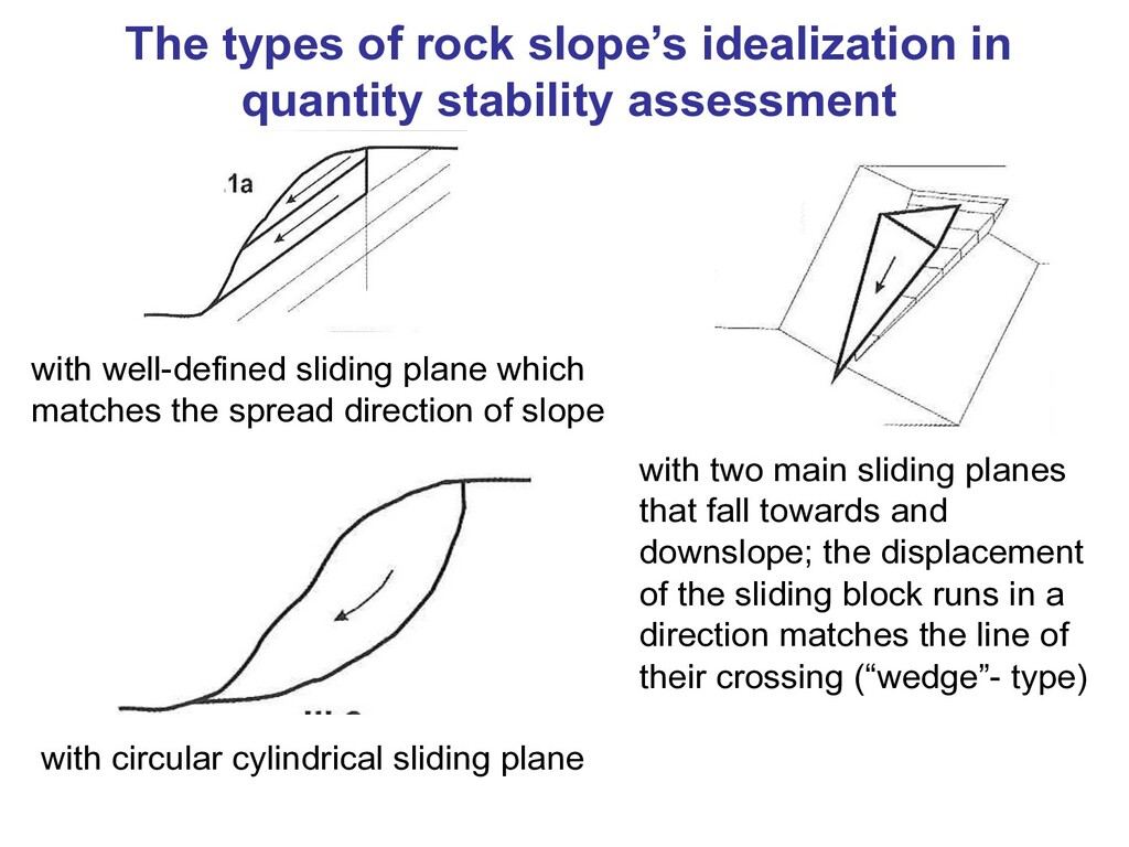
with well-defined sliding plane which matches the spread direction of slope with two main sliding planes that fall towards and downslope; the displacement of the sliding block runs in a direction matches the line of their crossing (“wedge”- type) with circular cylindrical sliding plane
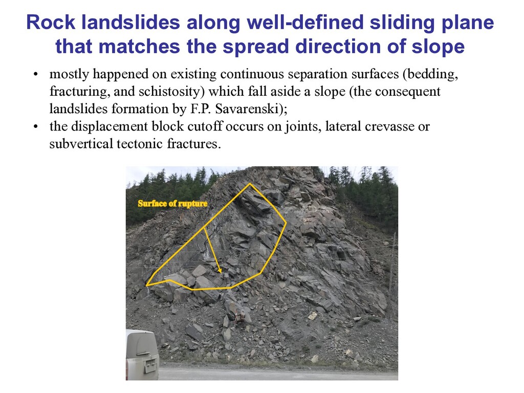
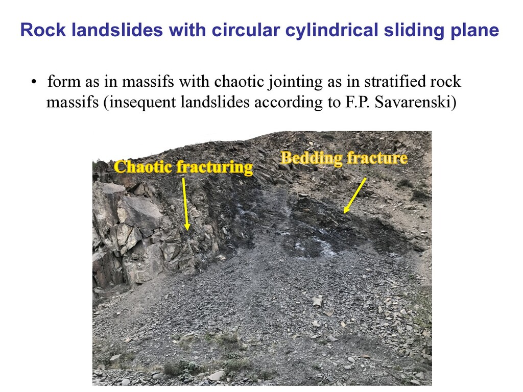
direction of slope • mostly happened on existing continuous separation surfaces (bedding, fracturing, and schistosity) which fall aside a slope (the consequent landslides formation by F.P. Savarenski); • the displacement block cutoff occurs on joints, lateral crevasse or subvertical tectonic fractures.
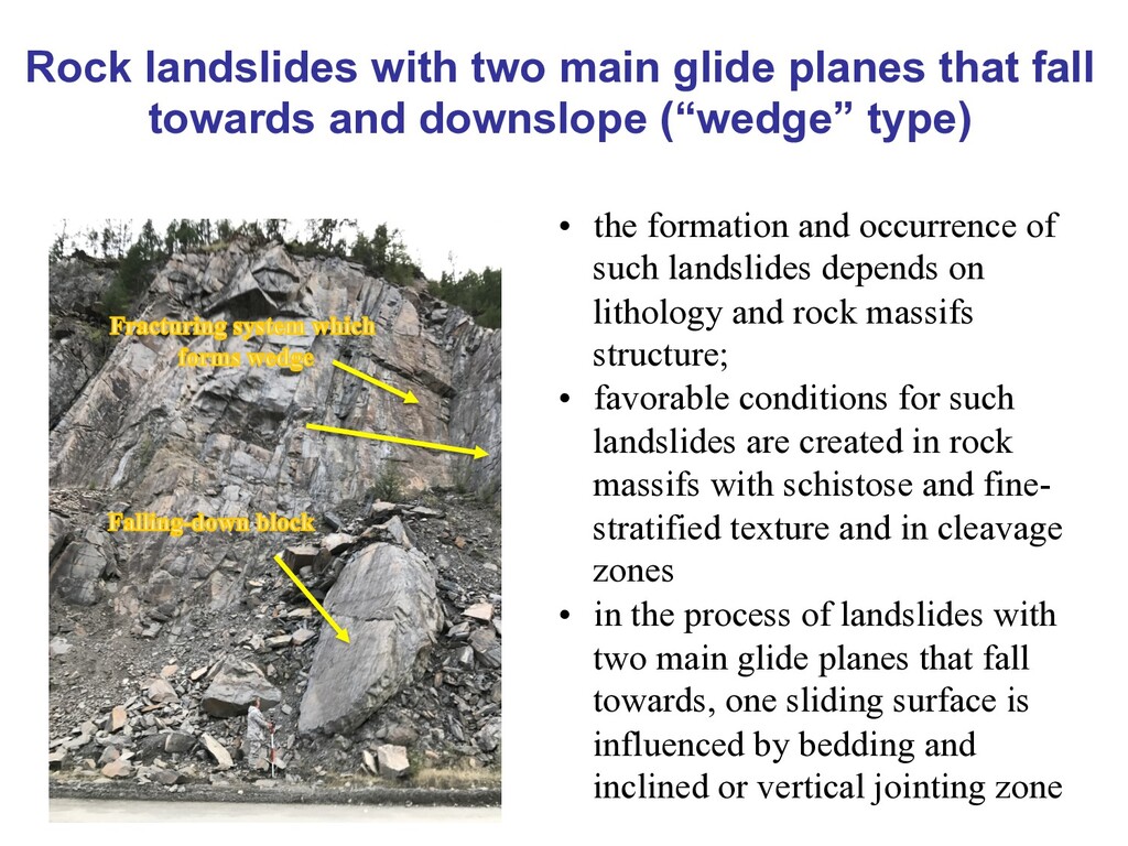
and downslope (“wedge” type) • the formation and occurrence of such landslides depends on lithology and rock massifs structure; • favorable conditions for such landslides are created in rock massifs with schistose and fine- stratified texture and in cleavage zones • in the process of landslides with two main glide planes that fall towards, one sliding surface is influenced by bedding and inclined or vertical jointing zone
were chosen to perform the stability assessment: 1. variants which solve the rock landslides stability assessment problem in case of circular cylindrical sliding plane (without existing surface of separation straight): - method of limit equilibrium group which includes Morgenstern- Price, simplified Bishop’s and Janby’s methods [5]; - finite elements method which represent numerical method class. 2. variants which assess the stability on the base of existing surface of separation: - method of limit equilibrium group which includes Morgenstern- Price, simplified Bishop’s and Janby’s methods; - finite elements method; - method of volume rock blocks assessment (for the “wedge” type landslides).
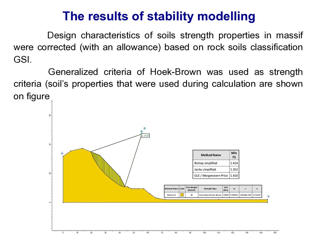
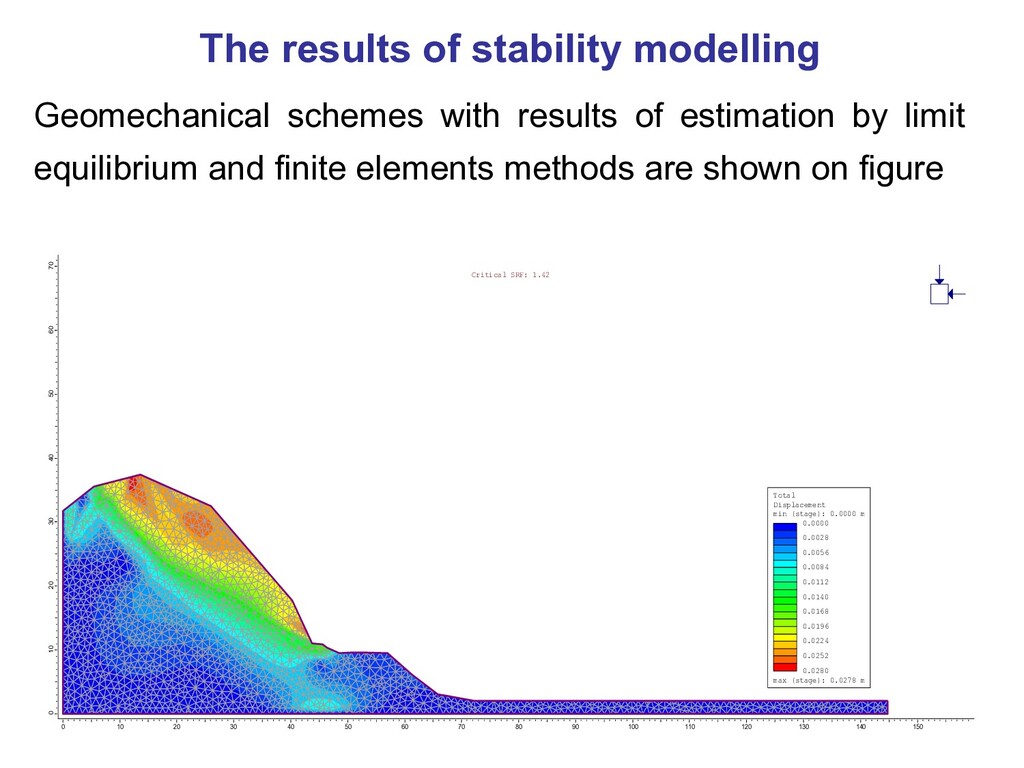
properties in massif were corrected (with an allowance) based on rock soils classification GSI. Generalized criteria of Hoek-Brown was used as strength criteria (soil’s properties that were used during calculation are shown on figure 1.410 1.410 1.410 1.410 1.410 1.410 Method Name Min FS Bishop simplified 1.414 Janbu simplified 1.352 GLE / Morgenstern-Price 1.410 Material Name Color Unit Weight (kN/m3) Strength Type UCS (kPa) m s a Material 1 28 Generalized Hoek-Brown 50000 0.064921 1.90286e-005 0.531267 60 40 20 0 0 10 20 30 40 50 60 70 80 90 100 110 120 130 140 150
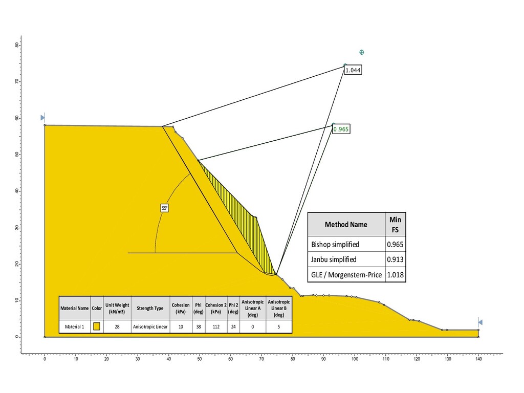
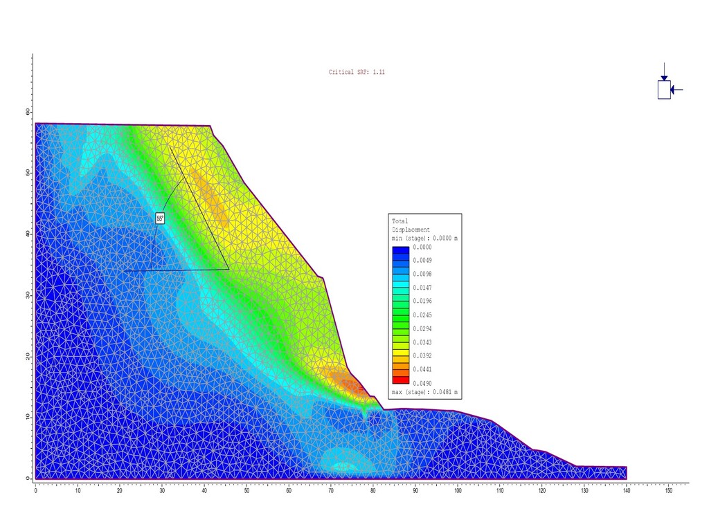
slope’s spread direction (dip angle is oriented along the slope) Linear anisotropic criteria was used as strength criteria (Snowden, 2007). Meanwhile as soil’s properties along fracture were chosen cohesion and friction angle (specified on the base of Barton-Bandis criteria [Barton 1990, Hoek E., 2002). In massif as soil’s properties were chosen equivalent cohesion and friction angle values that were calculated by conversion from Hoek-Brown criteria. Geomechanical schemes with results of estimation by limit equilibrium and finite elements methods are shown on next slides.
and downslope (“wedge” type) The sliding block of “wedge” type falling down analysis was organized for observed fracturing systems with the following slope parameters: - slope height 25 m; - dip angle/drop azimuth for slope’s surface - 65/245; - dip angle / drop azimuth for upper slope’s surface - 0/245; Strength properties along fractures: с = 10 kPa, φ = 38°.
other principles than sliding processes in dispersed soils. Calculation shows that on the considered territory may occur rock landslides of following types: 1. fracturing drop azimuth matches the slope’s drop azimuth (fracture falls «in slope»); 2. fracturing system drop azimuth does not match the slope’s drop azimuth. Formation of “wedge” type landslides requires confirmation by the results of kinematic analysis; 3. slope is broken by chaotic oriented fracturing system (the presence of oriented fractures fall «in slope» is allowed).