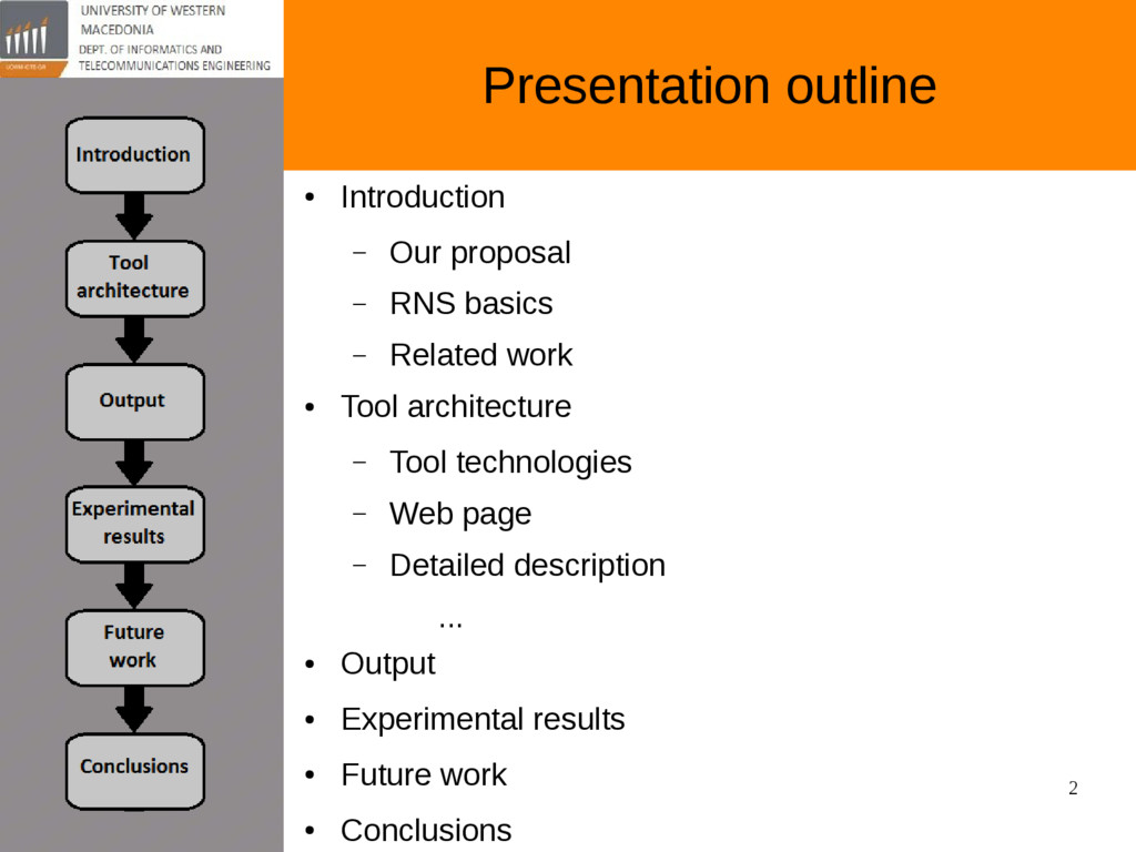
IP blocks converters from a network interface Minas Dasygenis [email protected] Department of Informatics and Telecommunications Engineering University of Western Macedonia, Kozani, Greece Presentation will be on github: • https://github.com/gpetrousov/pci2014_conference
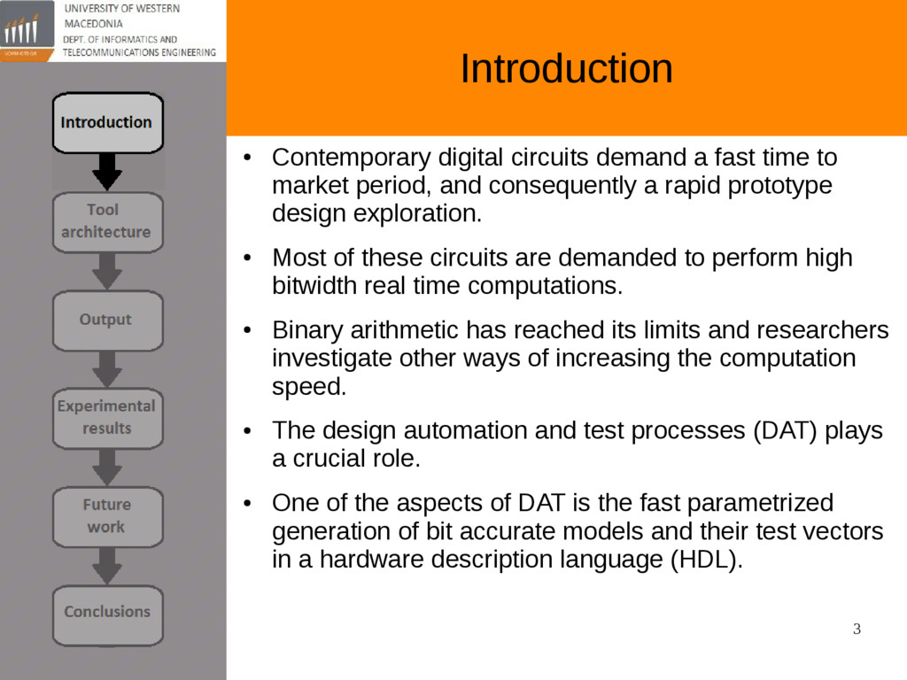
to market period, and consequently a rapid prototype design exploration. • Most of these circuits are demanded to perform high bitwidth real time computations. • Binary arithmetic has reached its limits and researchers investigate other ways of increasing the computation speed. • The design automation and test processes (DAT) plays a crucial role. • One of the aspects of DAT is the fast parametrized generation of bit accurate models and their test vectors in a hardware description language (HDL).
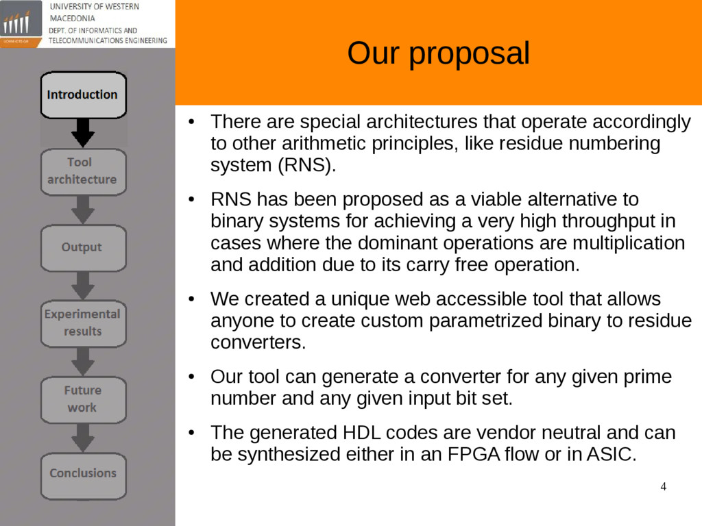
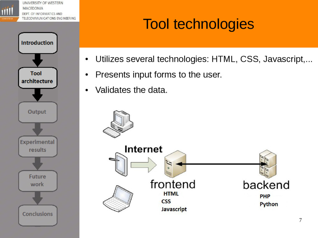
accordingly to other arithmetic principles, like residue numbering system (RNS). • RNS has been proposed as a viable alternative to binary systems for achieving a very high throughput in cases where the dominant operations are multiplication and addition due to its carry free operation. • We created a unique web accessible tool that allows anyone to create custom parametrized binary to residue converters. • Our tool can generate a converter for any given prime number and any given input bit set. • The generated HDL codes are vendor neutral and can be synthesized either in an FPGA flow or in ASIC.
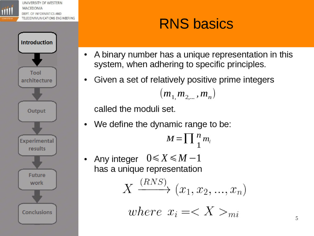
representation in this system, when adhering to specific principles. • Given a set of relatively positive prime integers called the moduli set. • We define the dynamic range to be: • Any integer has a unique representation (m 1, m 2,... ,m n ) 0⩽X⩽M −1 M =∏ n 1 m i
done on Residue Numbering System. • Google Scholar yields more than 2,950,000 results. • To our best knowledge there is no similar tool that accepts parameters and generates optimal synthesizable VHDL architecture.
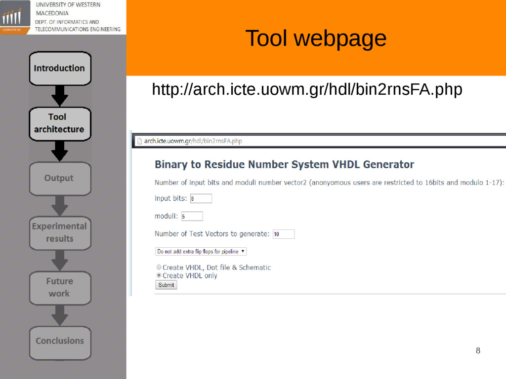
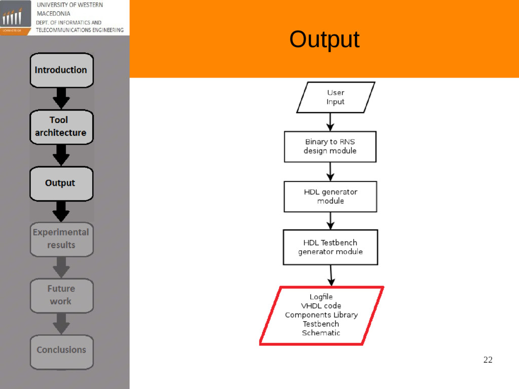
number determines the greatest number our converter will be able to process. • Moduli: any positive prime integer. Must be greater or equal to the greatest formable number above so the user don't get repeating results. • Test vectors: this number determines the amount of random test vectors to be created to test the correctness of the generated converter. • Pipeline: pipeline by a fixed way, by inserting D-flip flops. • VHDL & Schematic: the output can contain only the generated VHDL, or it can contain the code plus a schematic of the converter.
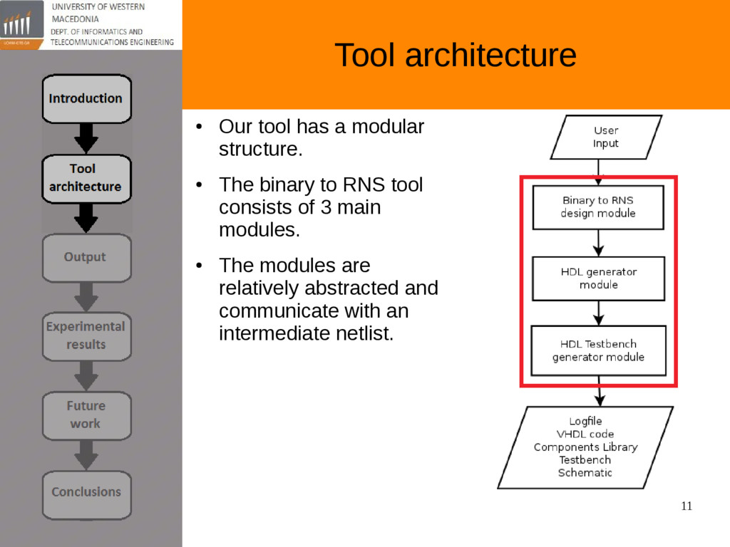
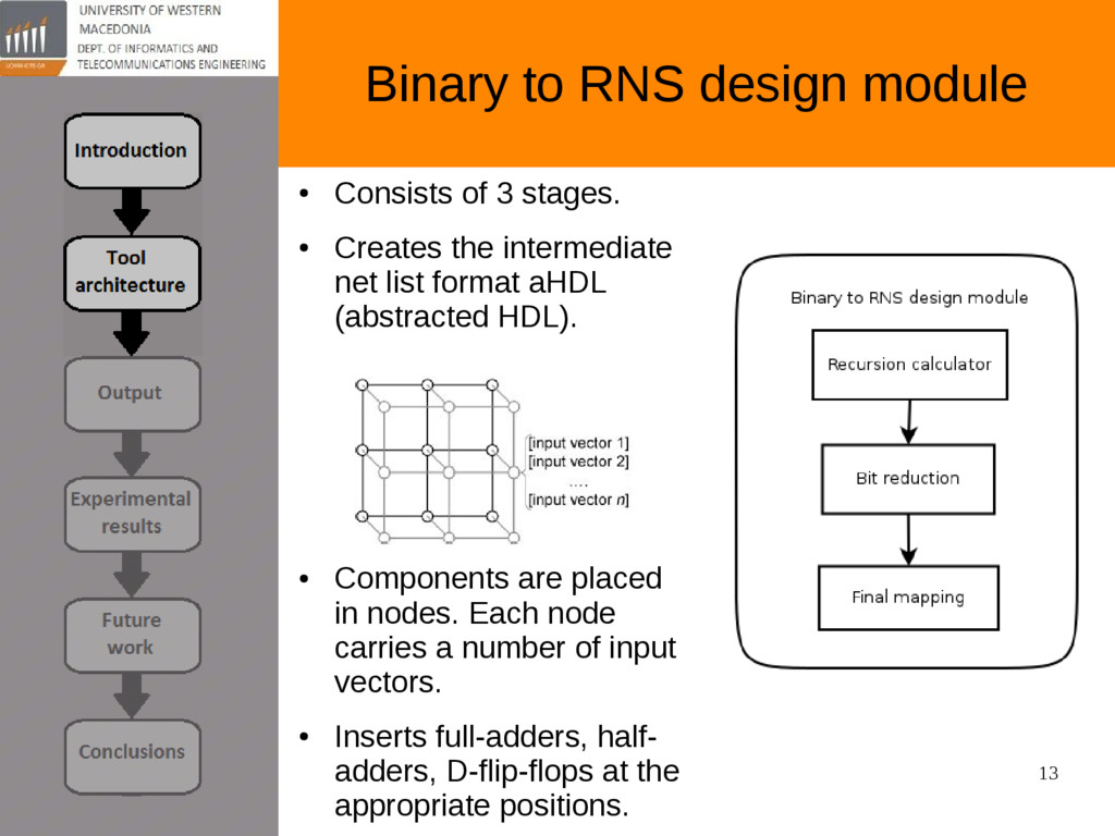
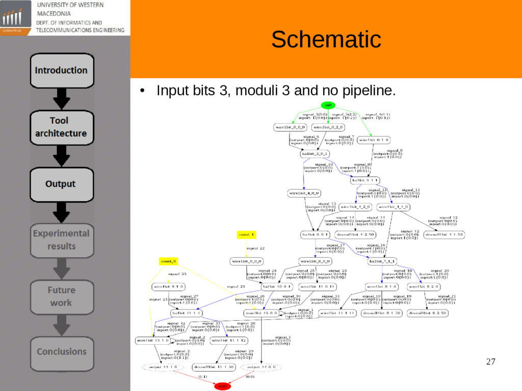
stages. • Creates the intermediate net list format aHDL (abstracted HDL). • Components are placed in nodes. Each node carries a number of input vectors. • Inserts full-adders, half- adders, D-flip-flops at the appropriate positions.
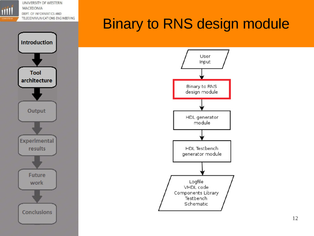
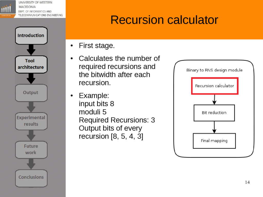
of required recursions and the bitwidth after each recursion. • Example: input bits 8 moduli 5 Required Recursions: 3 Output bits of every recursion [8, 5, 4, 3]
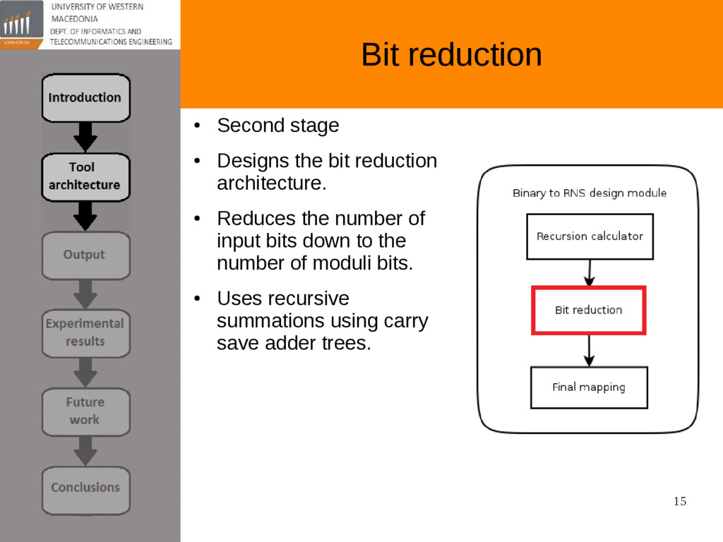
reduction architecture. • Reduces the number of input bits down to the number of moduli bits. • Uses recursive summations using carry save adder trees.
of two paths. • First path is for the case where the output of the previous stage is greater than the moduli. In this case a substruction is performed. • Second path is for the case when no substraction is needed.
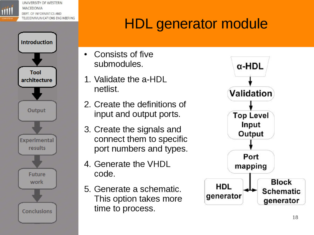
Validate the a-HDL netlist. 2. Create the definitions of input and output ports. 3. Create the signals and connect them to specific port numbers and types. 4. Generate the VHDL code. 5. Generate a schematic. This option takes more time to process.
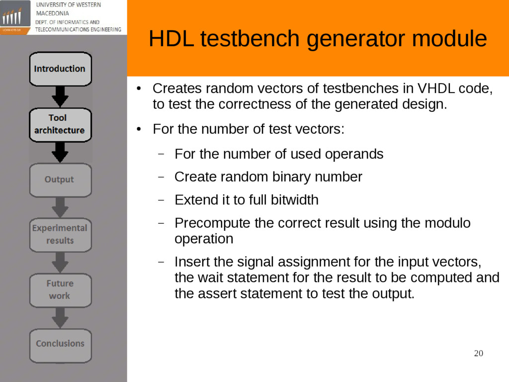
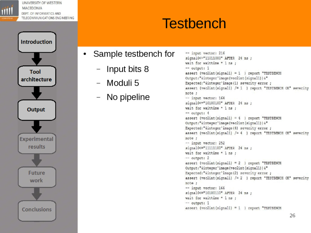
testbenches in VHDL code, to test the correctness of the generated design. • For the number of test vectors: – For the number of used operands – Create random binary number – Extend it to full bitwidth – Precompute the correct result using the modulo operation – Insert the signal assignment for the input vectors, the wait statement for the result to be computed and the assert statement to test the output.
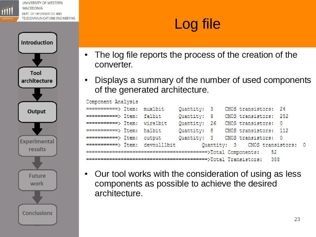
of the creation of the converter. • Displays a summary of the number of used components of the generated architecture. • Our tool works with the consideration of using as less components as possible to achieve the desired architecture.
create custom functions. • Create the rest of the line RNS converters and backward converters, like QRNS, RNS to binary. • Define the number of pipeline stages. • Generate output in other HDL languages, like Verilog. • Create an API so the tool can be used in a machine-to- machine scenario.
finds the most optimal combination of prime numbers to be used in the converter architecture. • This processes becomes computationally intensive for large numbers. • We have also developed the option to generate unique random testvectors for the testbench.
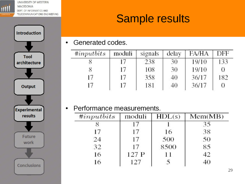
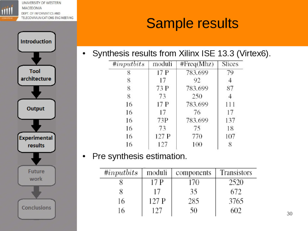
foundation for increasing productivity and achieving fast time-to-market constraints. • We presented the first web accessible tool to create custom binary to residue converters. • Our tool outputs syntactically correct VHDL files, a custom automated testbench, a block schematic and other metrics. • The derived architectures are optimized designs. • Synthesis results indicate the high performance on the Xilinx Virtex 6 FPGA, with operational frequencies up to 783 Mhz. • The generated code is vendor neutral and can be synthesized in FPGA or in ASIC projects.
![1 Ioannis Petrousov [email protected] Designing optimized forward residue number systems](https://files.speakerdeck.com/presentations/06d89457ca504f80b01550b34a374f19/slide_0.jpg)