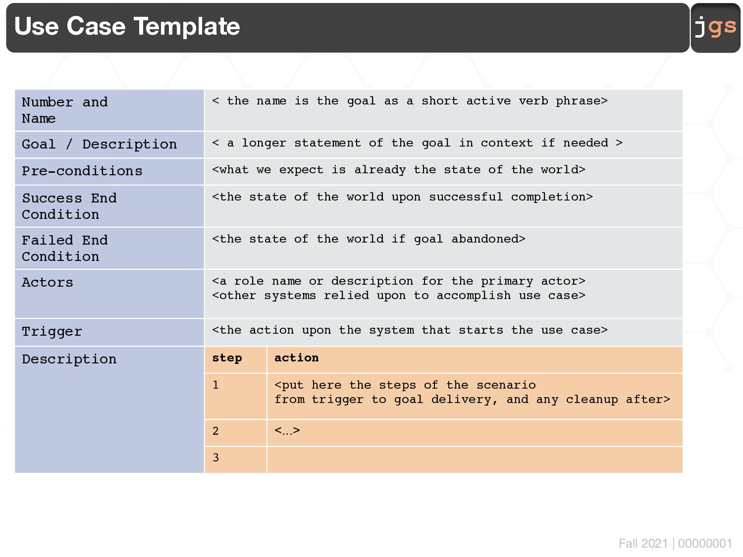
Name < the name is the goal as a short active verb phrase> Goal / Description < a longer statement of the goal in context if needed > Pre-conditions <what we expect is already the state of the world> Success End Condition <the state of the world upon successful completion> Failed End Condition <the state of the world if goal abandoned> Actors <a role name or description for the primary actor> <other systems relied upon to accomplish use case> Trigger <the action upon the system that starts the use case> Description step action 1 <put here the steps of the scenario from trigger to goal delivery, and any cleanup after> 2 <...> 3
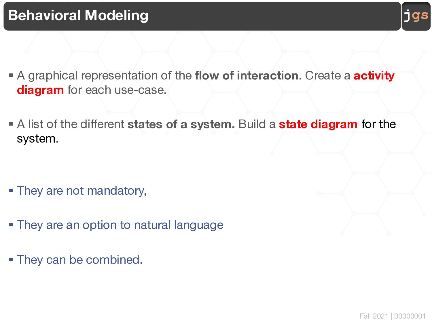
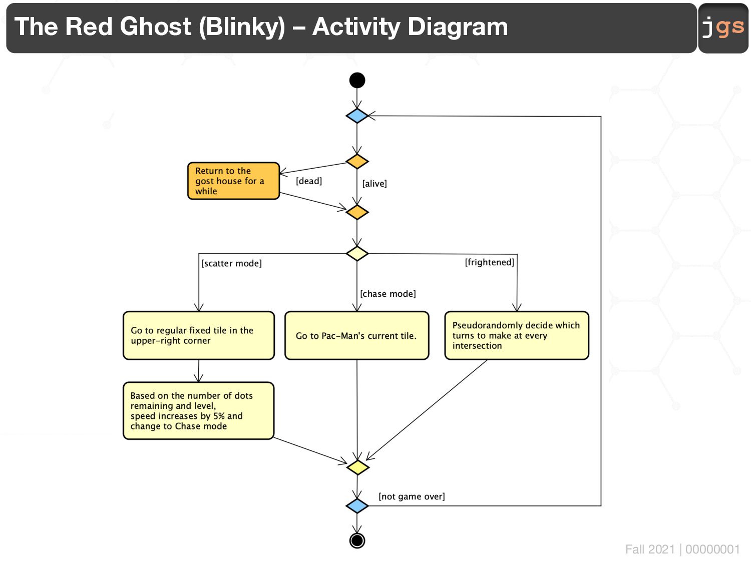
representation of the flow of interaction. Create a activity diagram for each use-case. § A list of the different states of a system. Build a state diagram for the system. § They are not mandatory, § They are an option to natural language § They can be combined.
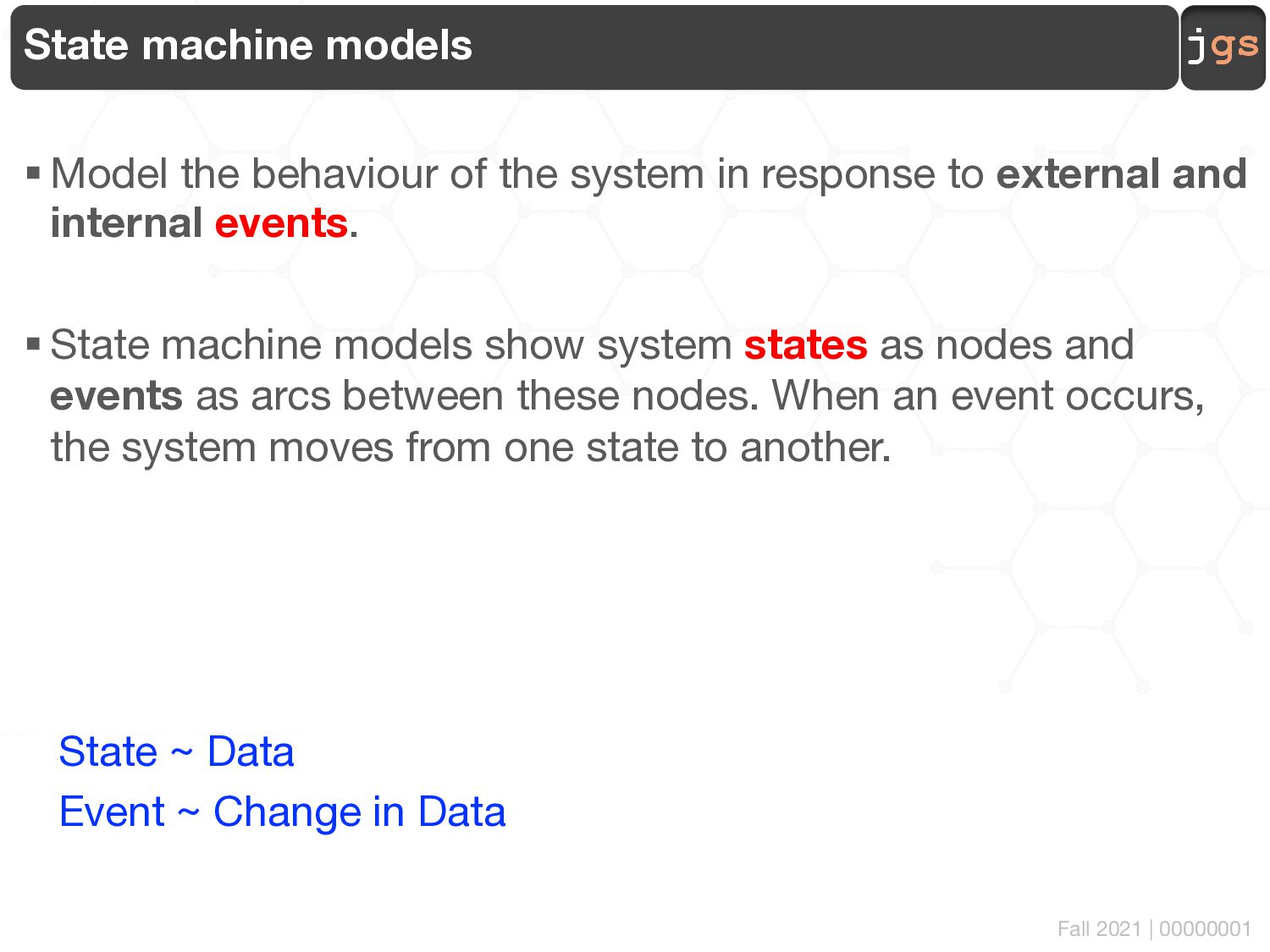
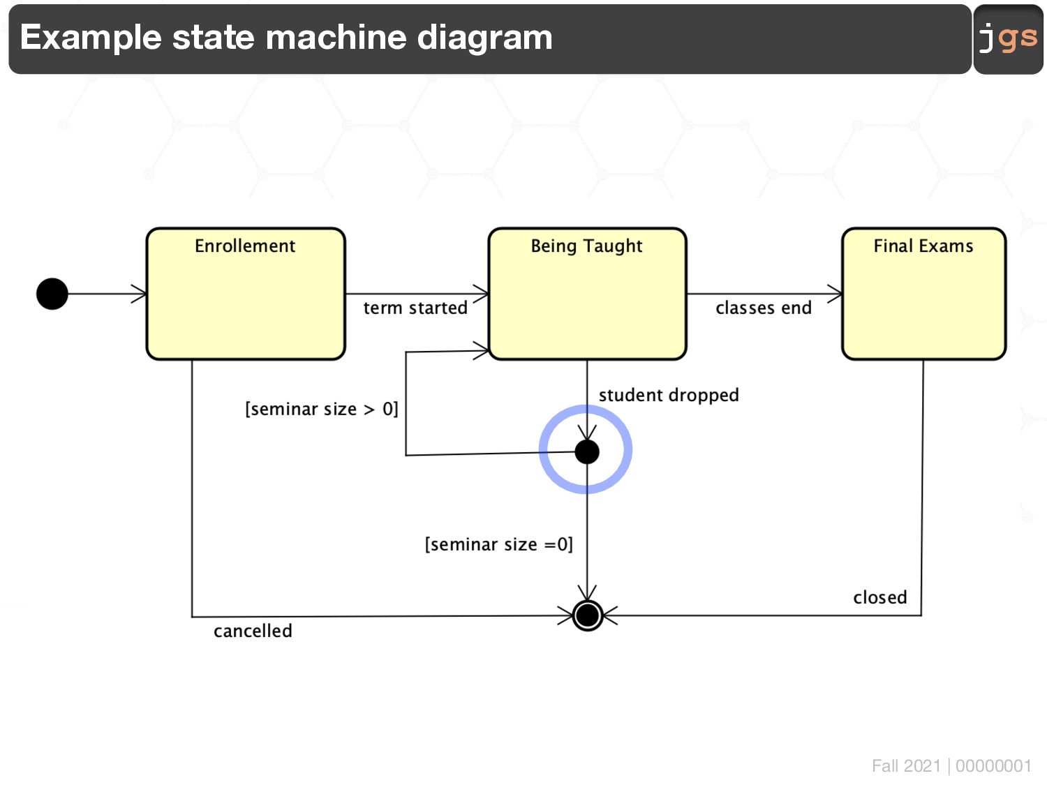
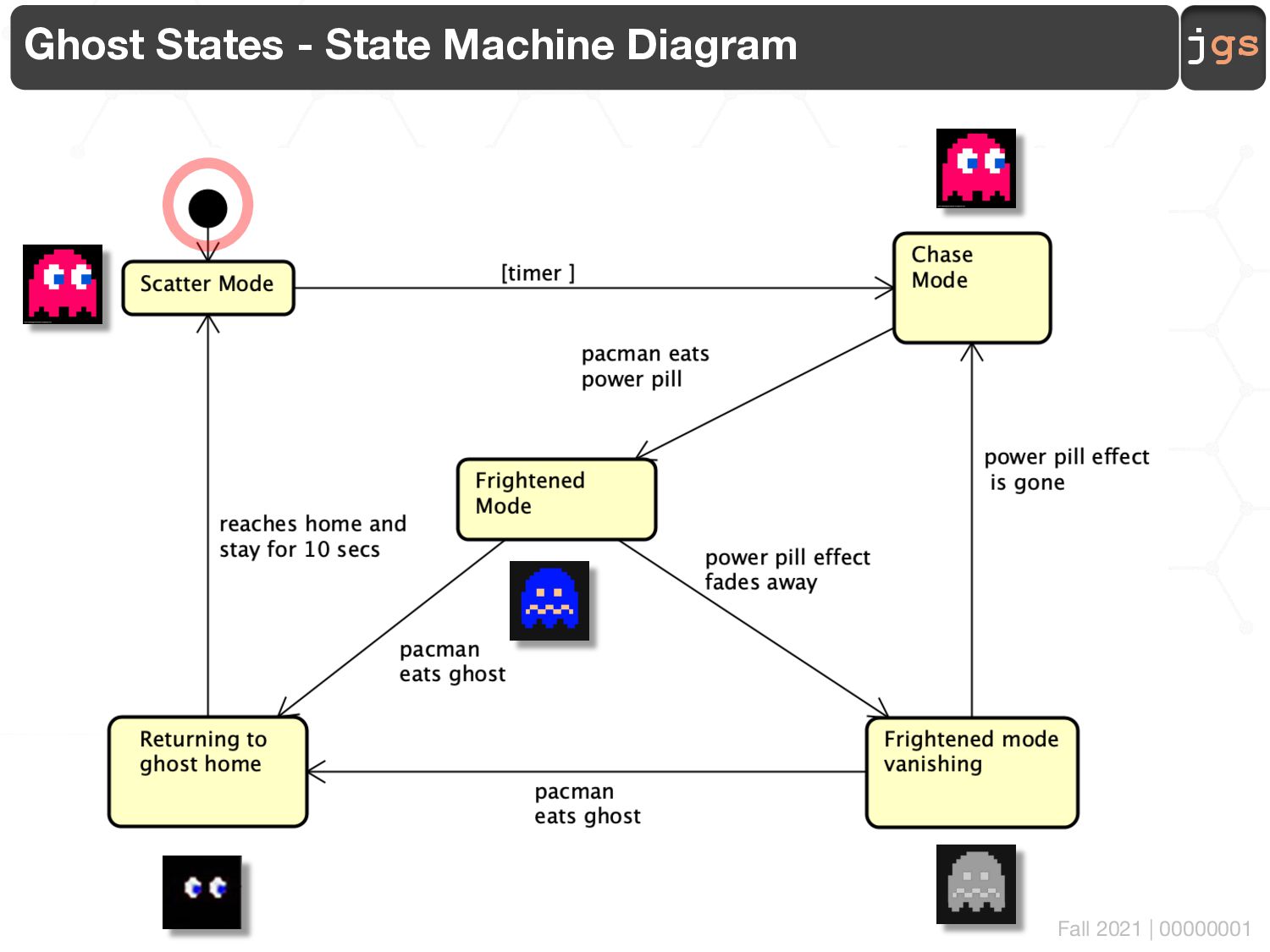
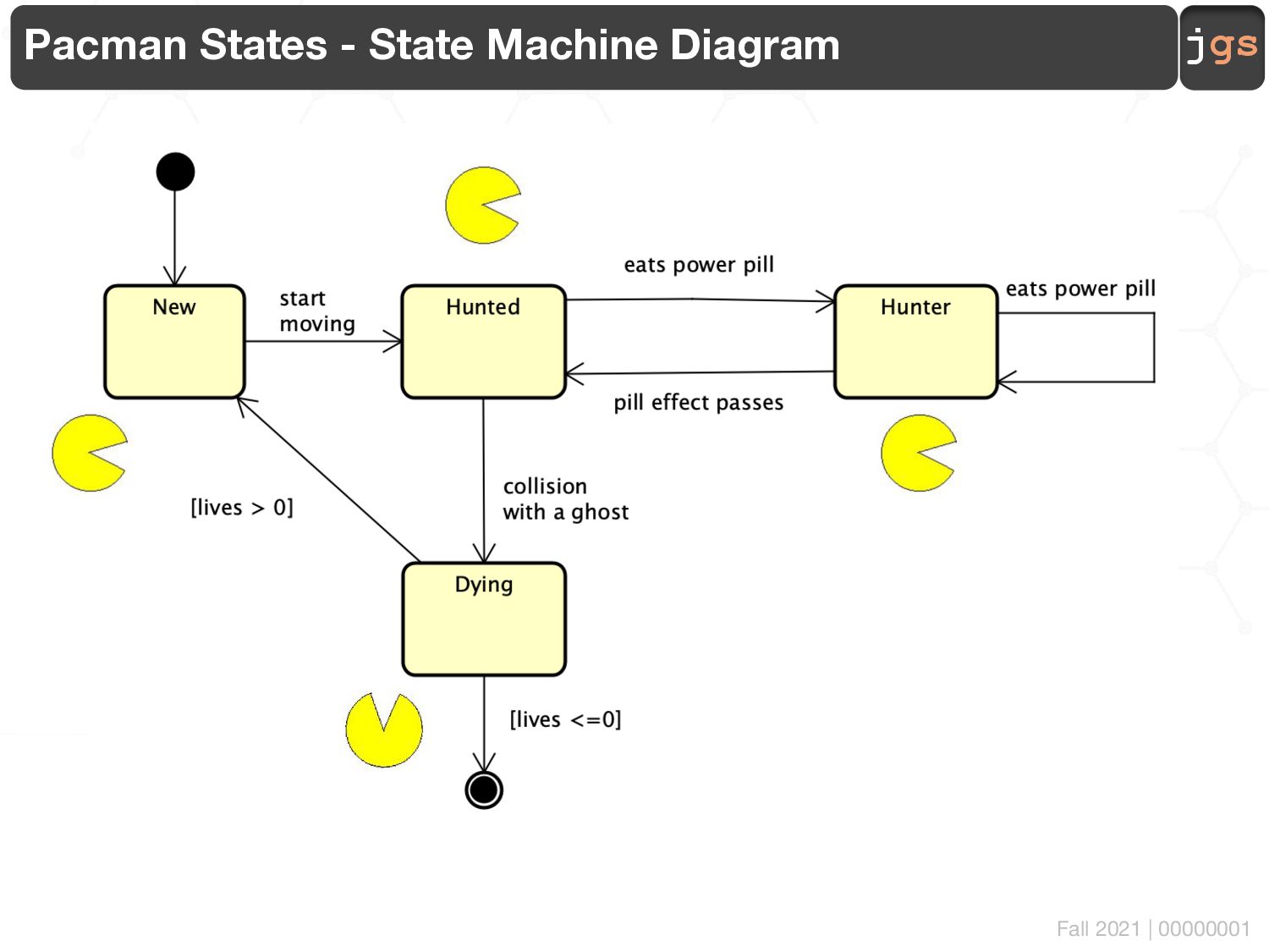
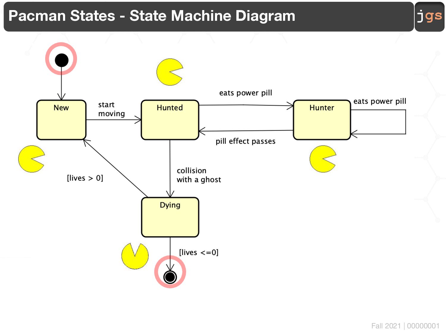
the behaviour of the system in response to external and internal events. § State machine models show system states as nodes and events as arcs between these nodes. When an event occurs, the system moves from one state to another. State ~ Data Event ~ Change in Data
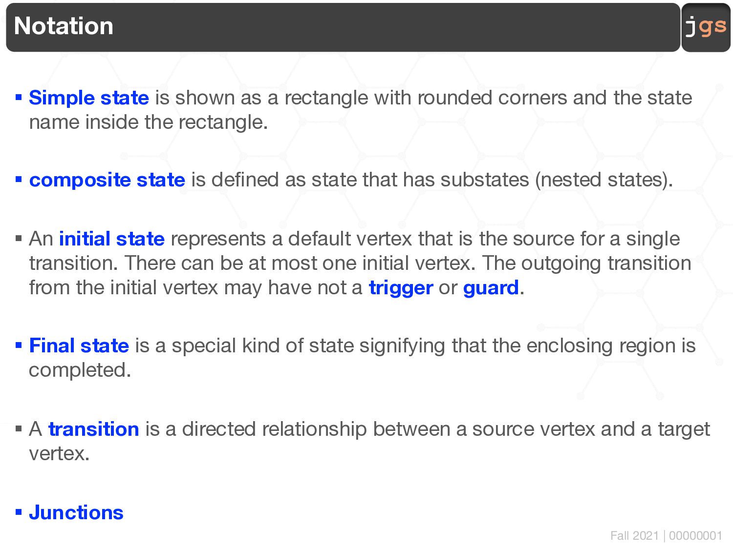
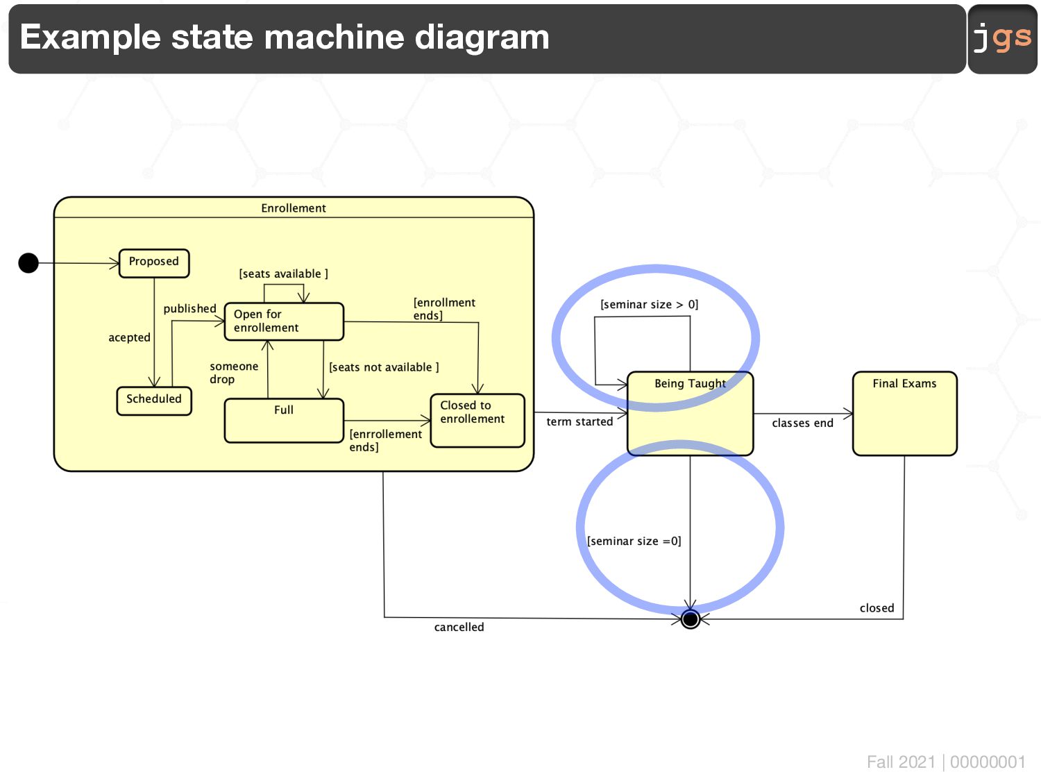
shown as a rectangle with rounded corners and the state name inside the rectangle. § composite state is defined as state that has substates (nested states). § An initial state represents a default vertex that is the source for a single transition. There can be at most one initial vertex. The outgoing transition from the initial vertex may have not a trigger or guard. § Final state is a special kind of state signifying that the enclosing region is completed. § A transition is a directed relationship between a source vertex and a target vertex. § Junctions
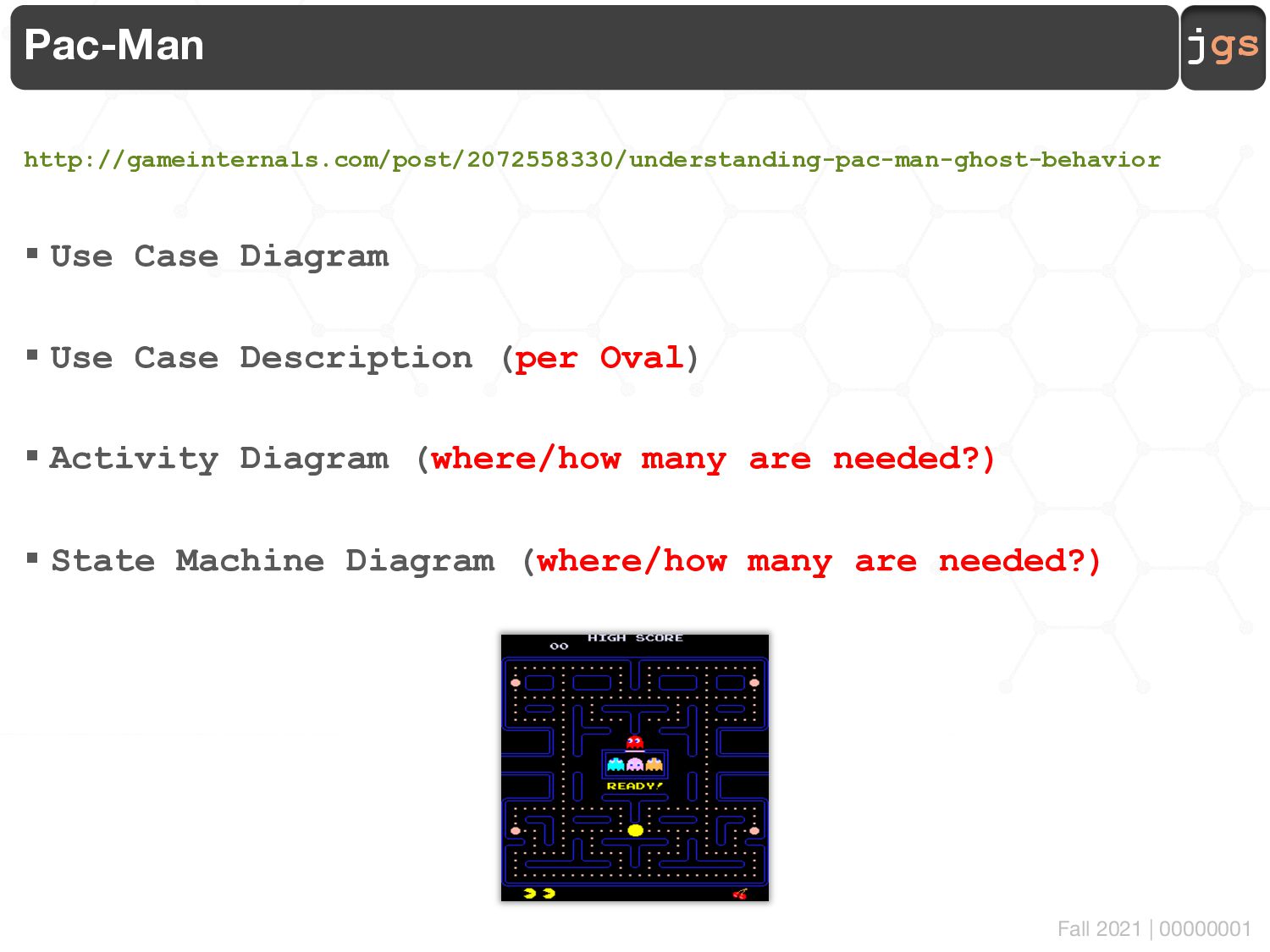
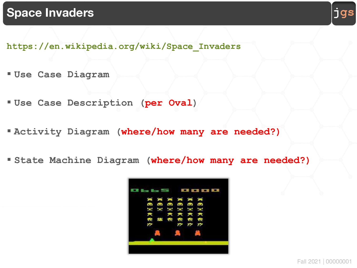
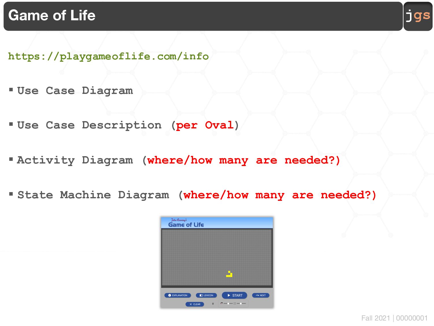
Use Case Diagram § Use Case Description (per Oval) § Activity Diagram (where/how many are needed?) § State Machine Diagram (where/how many are needed?)
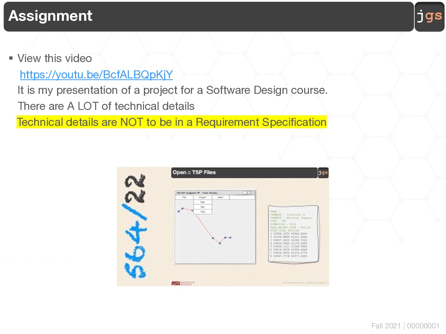
https://youtu.be/BcfALBQpKjY It is my presentation of a project for a Software Design course. There are A LOT of technical details Technical details are NOT to be in a Requirement Specification
Specification including a) Mandatory. A Use Case Diagram (showing all the actors, requirements, and relationships as needed) b) Mandatory. Per each Use Case, complete a Use Case Template. Yes, the one with triggers, pre-conditions, etc. etc. etc. Use all as needed. c) Question (you tell me). Per each Use Case, Do an activity diagram is need here or plain English? When and How to choose one or the other? d) Question (you tell me). Per each Use Case, Do a state machine diagram is need here or plain English? When and How to choose one or the other?
a mixture or Game Of Line and Another Video that I asked you to watch and report before § Hint. TSP (mentioned in the video) is a Technical Concept. User do not know that thing. Should I explain or ignore? If explain where? How? § What is the goal of all this (each diagram and each row in the template)? § How many diagrams? As needed. § How do I know if I have everything? Remember Storyboarding…
file § Due date Friday 11:59 PM AZ Time § Work in a team of 1, 2 or 3. No, more that 3 are not allowed. It is a team assignment for you to have the chance to share ideas and brainstorm a solution § Follow academic integrity policies. Yes, helping friends in need by sharing your work with them IS an academic integrity violation (if they decided to submit what you share as their own)
[email protected] Fall 2021 Copyright. These slides can only be used as study material for the class CSE563 at ASU. They cannot be distributed or used for another purpose.