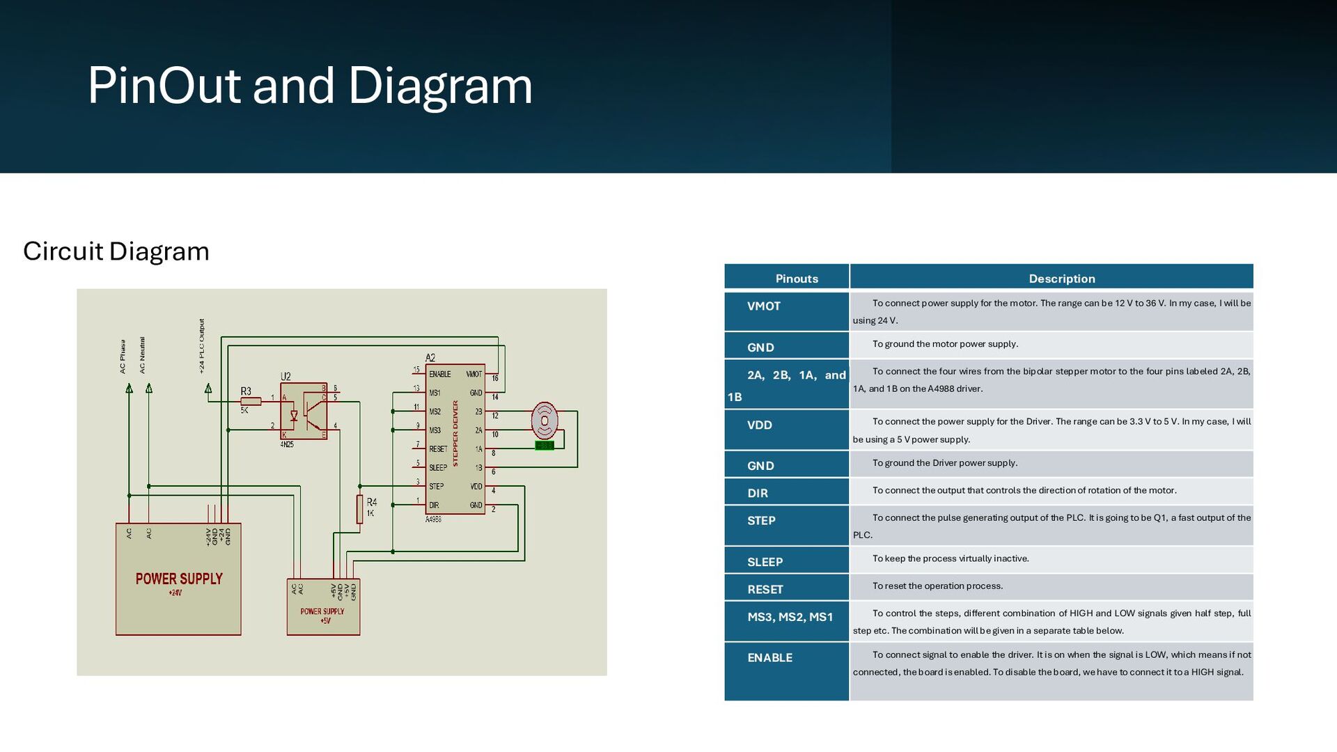
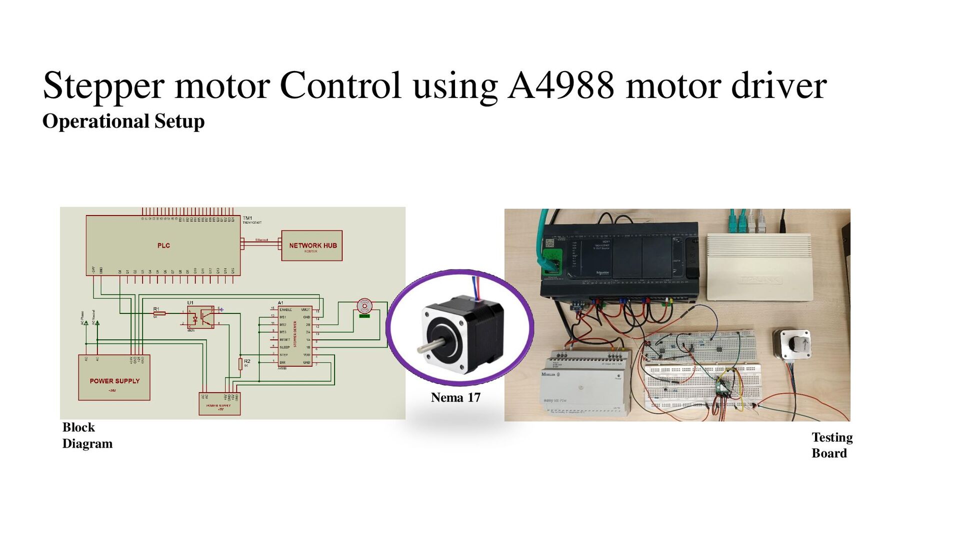
power supply for the motor. The range can be 12 V to 36 V. In my case, I will be using 24 V. GND To ground the motor power supply. 2A, 2B, 1A, and 1B To connect the four wires from the bipolar stepper motor to the four pins labeled 2A, 2B, 1A, and 1B on the A4988 driver. VDD To connect the power supply for the Driver. The range can be 3.3 V to 5 V. In my case, I will be using a 5 V power supply. GND To ground the Driver power supply. DIR To connect the output that controls the direction of rotation of the motor. STEP To connect the pulse generating output of the PLC. It is going to be Q1, a fast output of the PLC. SLEEP To keep the process virtually inactive. RESET To reset the operation process. MS3, MS2, MS1 To control the steps, different combination of HIGH and LOW signals given half step, full step etc. The combination will be given in a separate table below. ENABLE To connect signal to enable the driver. It is on when the signal is LOW, which means if not connected, the board is enabled. To disable the board, we have to connect it to a HIGH signal.
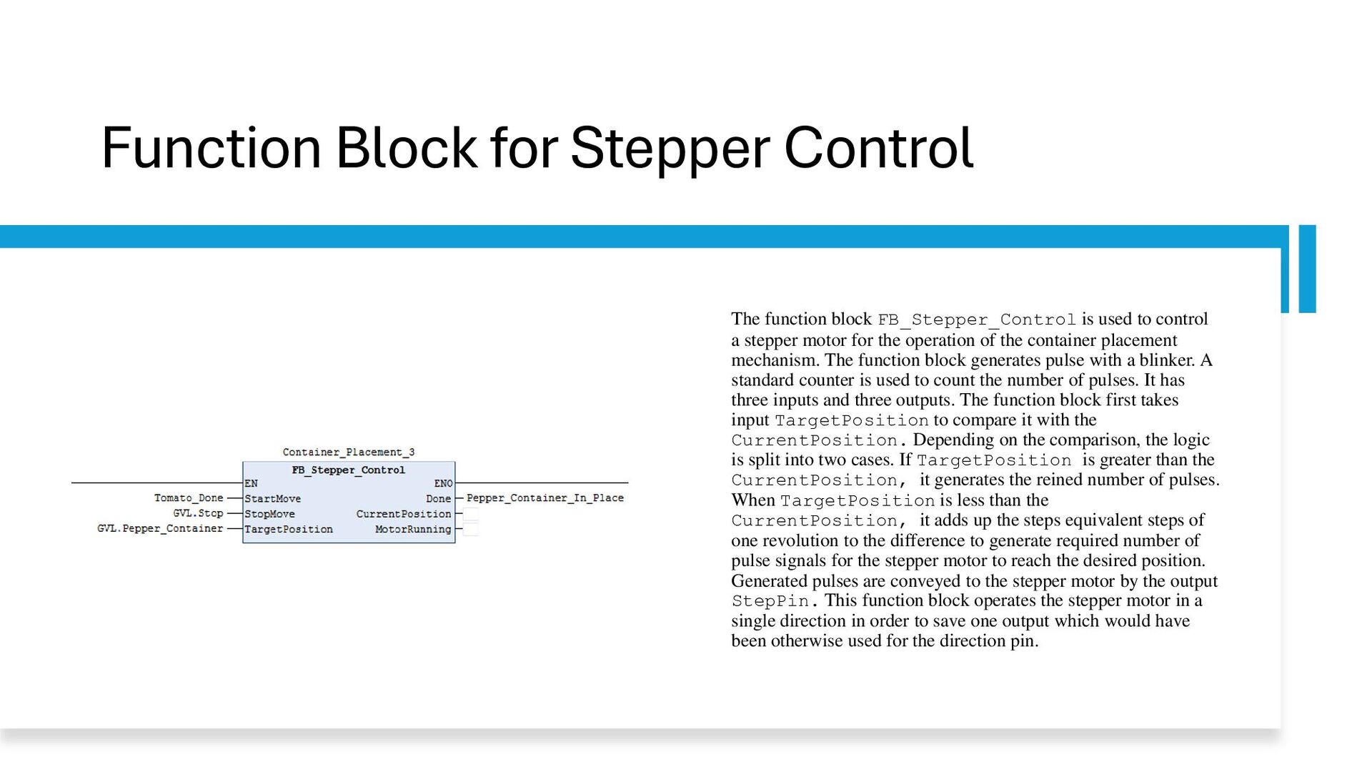
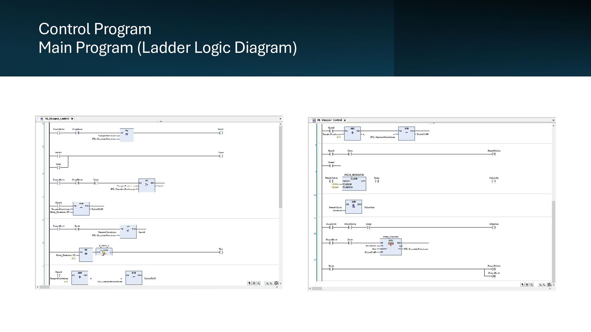
used to control a stepper motor for the operation of the container placement mechanism. The function block generates pulse with a blinker. A standard counter is used to count the number of pulses. It has three inputs and three outputs. The function block first takes input TargetPosition to compare it with the CurrentPosition. Depending on the comparison, the logic is split into two cases. If TargetPosition is greater than the CurrentPosition, it generates the reined number of pulses. When TargetPosition is less than the CurrentPosition, it adds up the steps equivalent steps of one revolution to the difference to generate required number of pulse signals for the stepper motor to reach the desired position. Generated pulses are conveyed to the stepper motor by the output StepPin. This function block operates the stepper motor in a single direction in order to save one output which would have been otherwise used for the direction pin.
• The power supply conversion for the A4988 board was accurate. • The logic level conversion of the pulse signal generated by the PLC was driving the stepper motor. • The generated pulse was enough to drive the motor using A4988 stepper drive. • The stepper motor was stopping at desired places as instructed by the program with accuracy. • The visualization control was working. • The procedure was possible to follow and control the operation using the web-visualization using both computer and mobile device.