Upgrade to Pro — share decks privately, control downloads, hide ads and more …

Inside Raspberry Pi GPIO

Inside Raspberry Pi GPIO

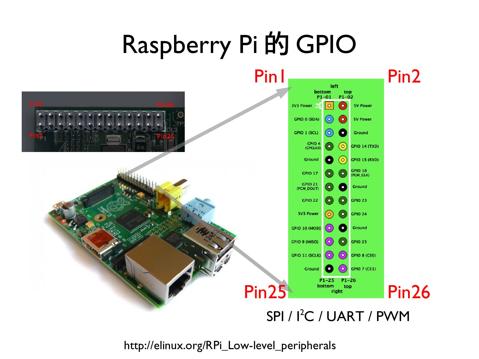
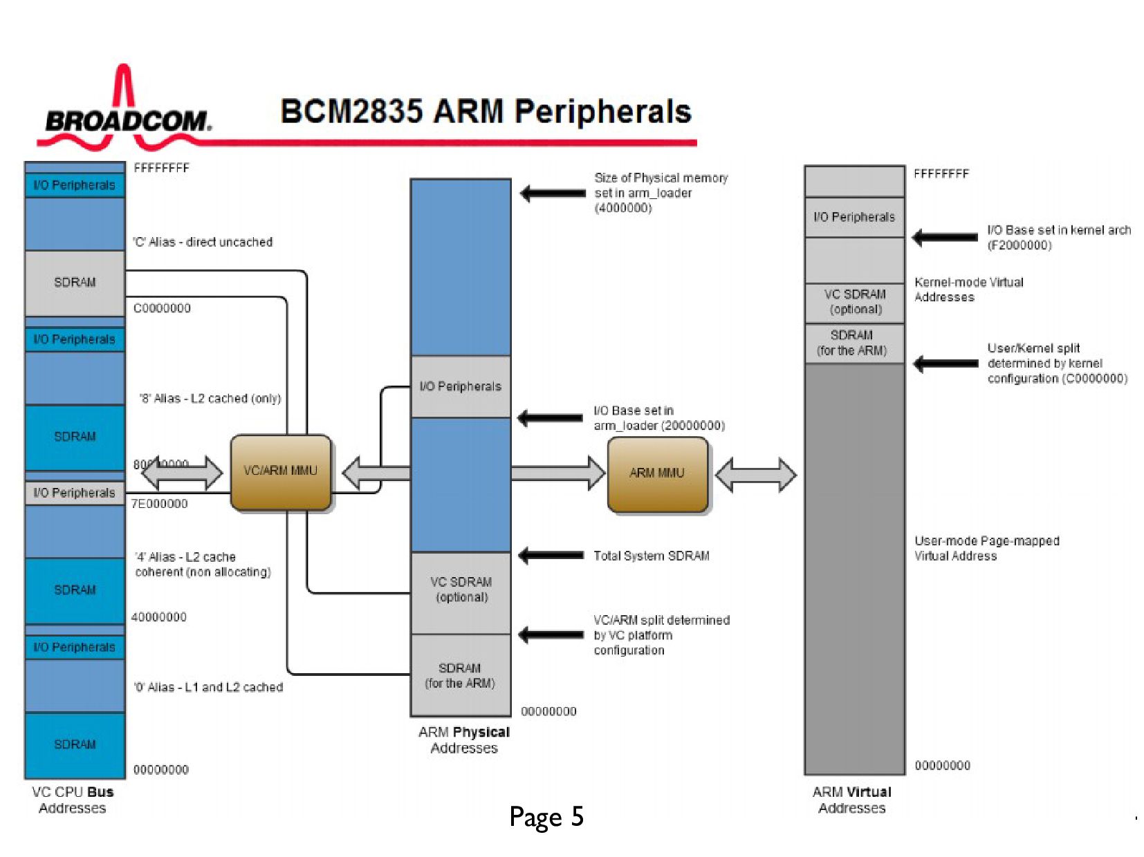
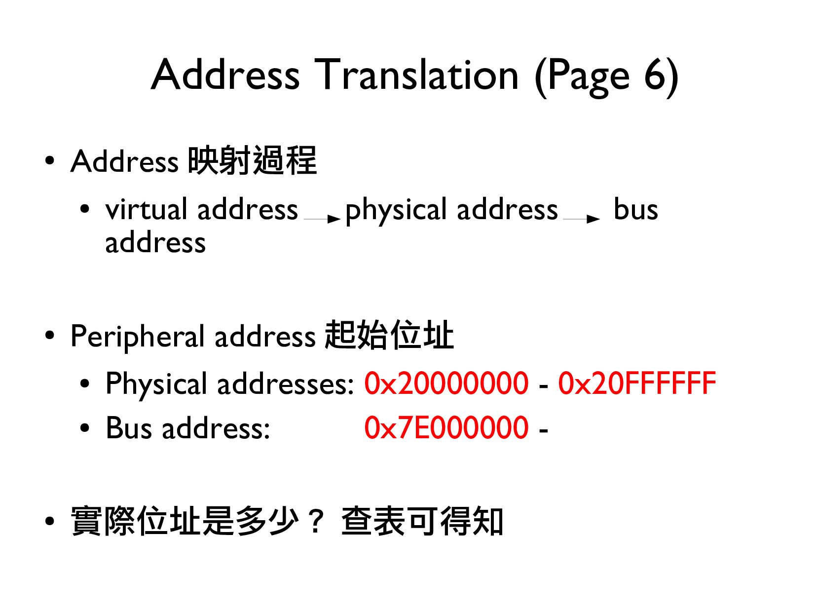
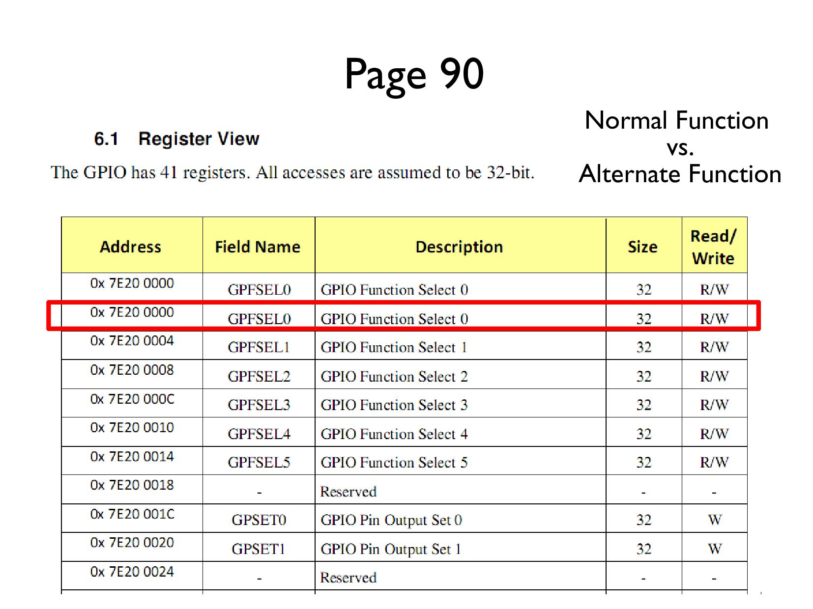
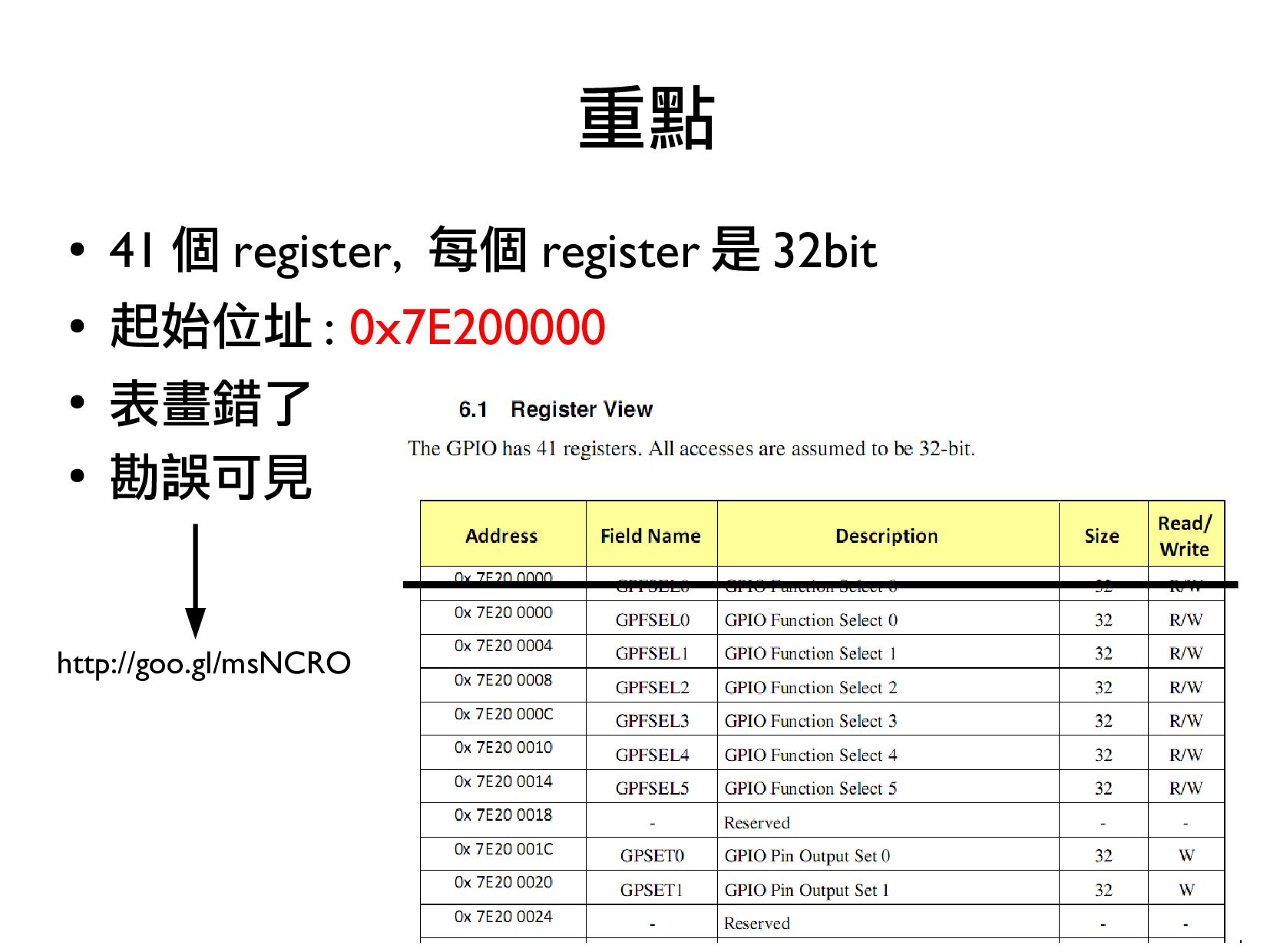
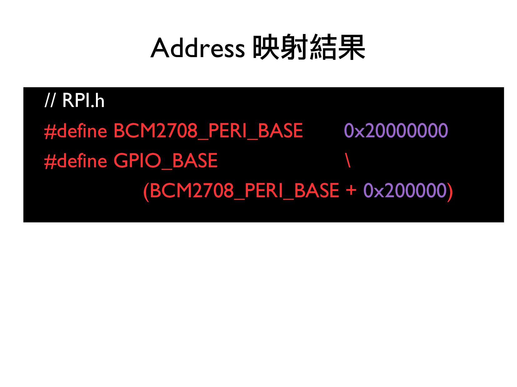
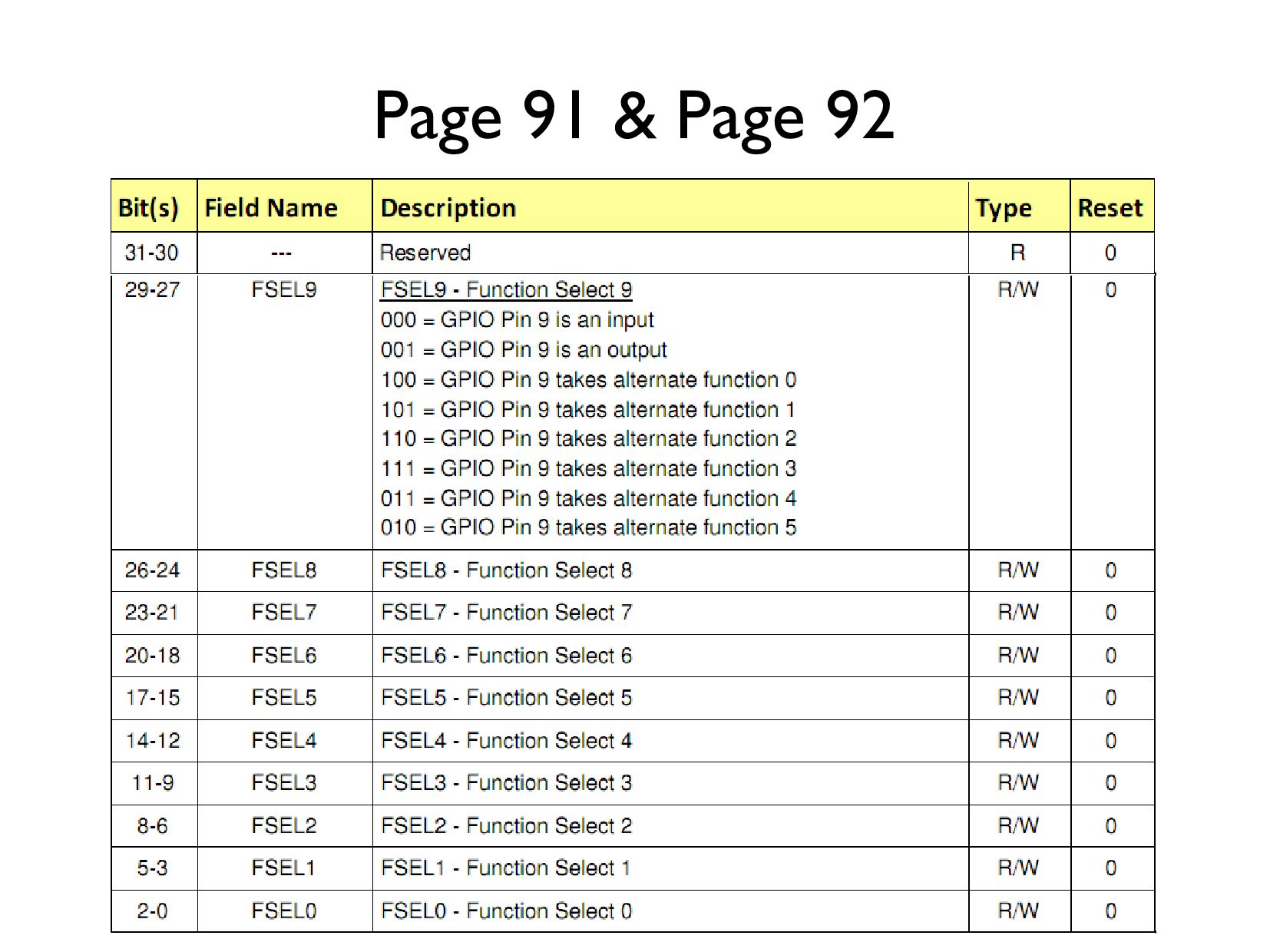
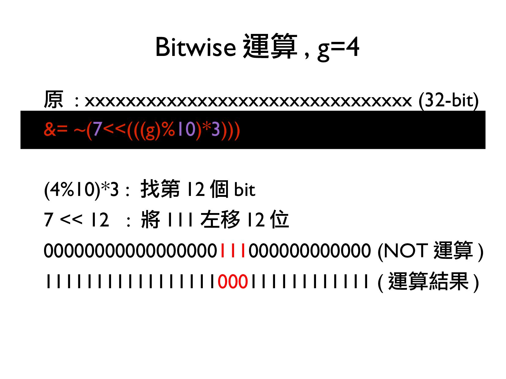
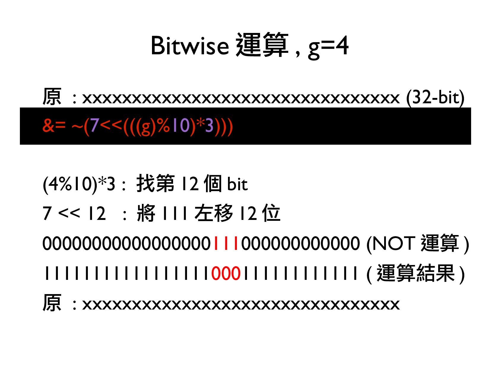
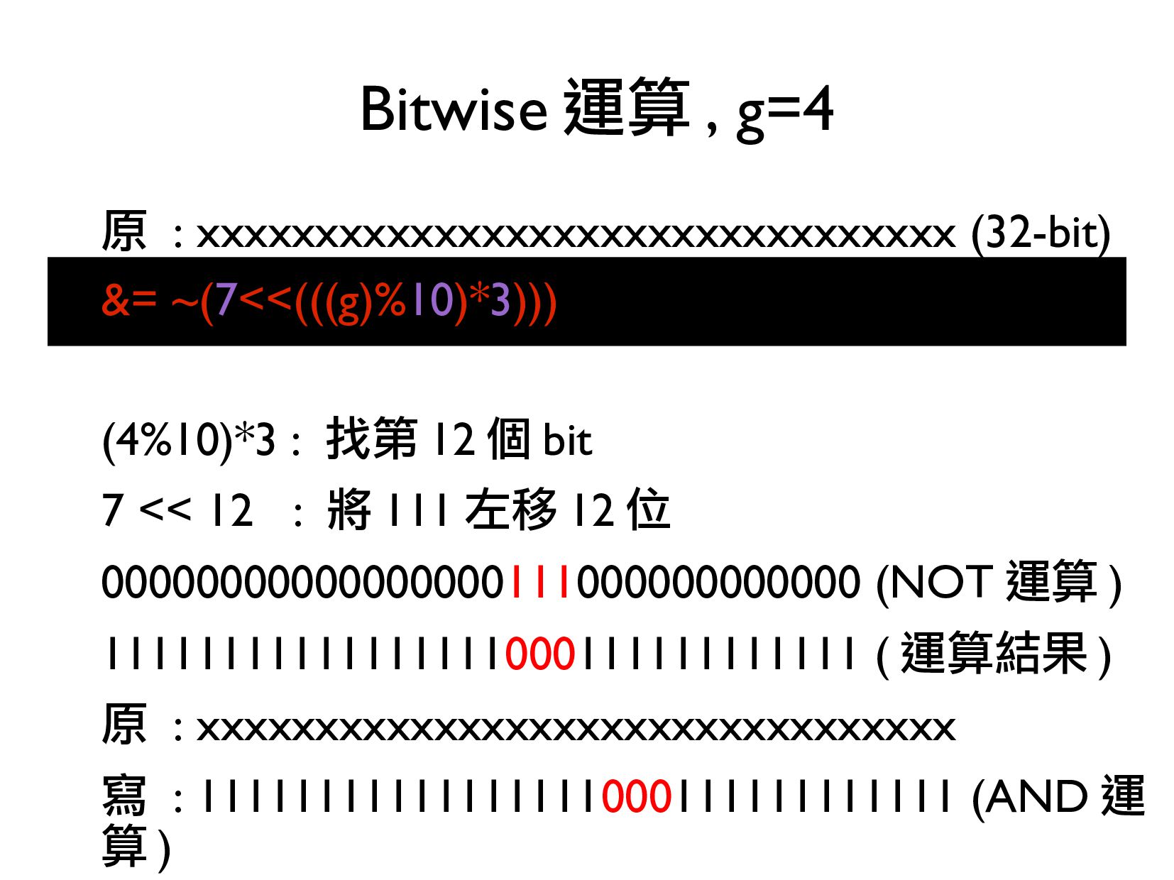
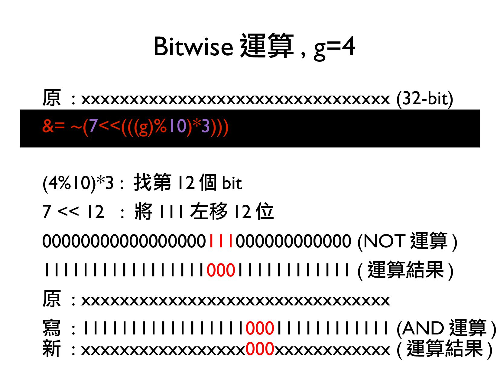
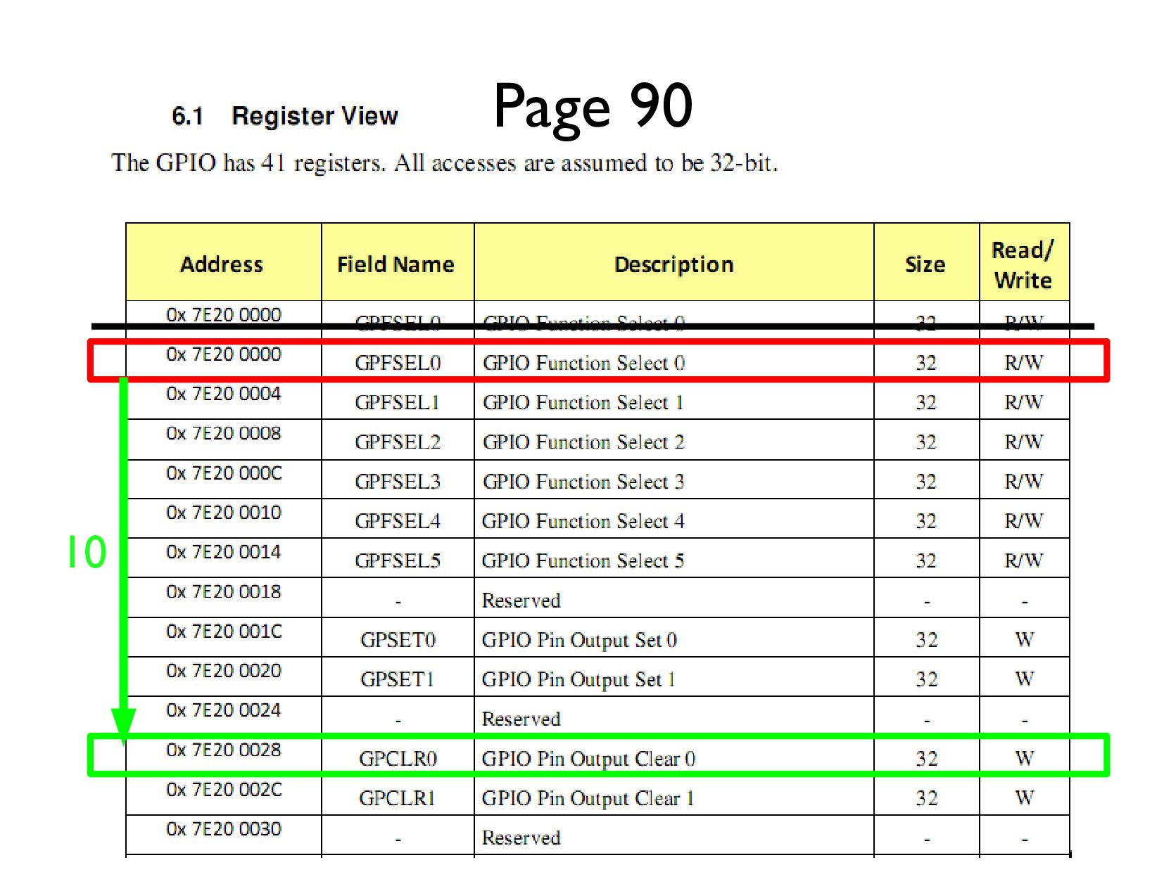
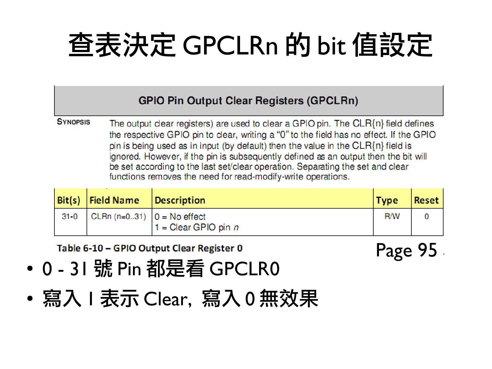
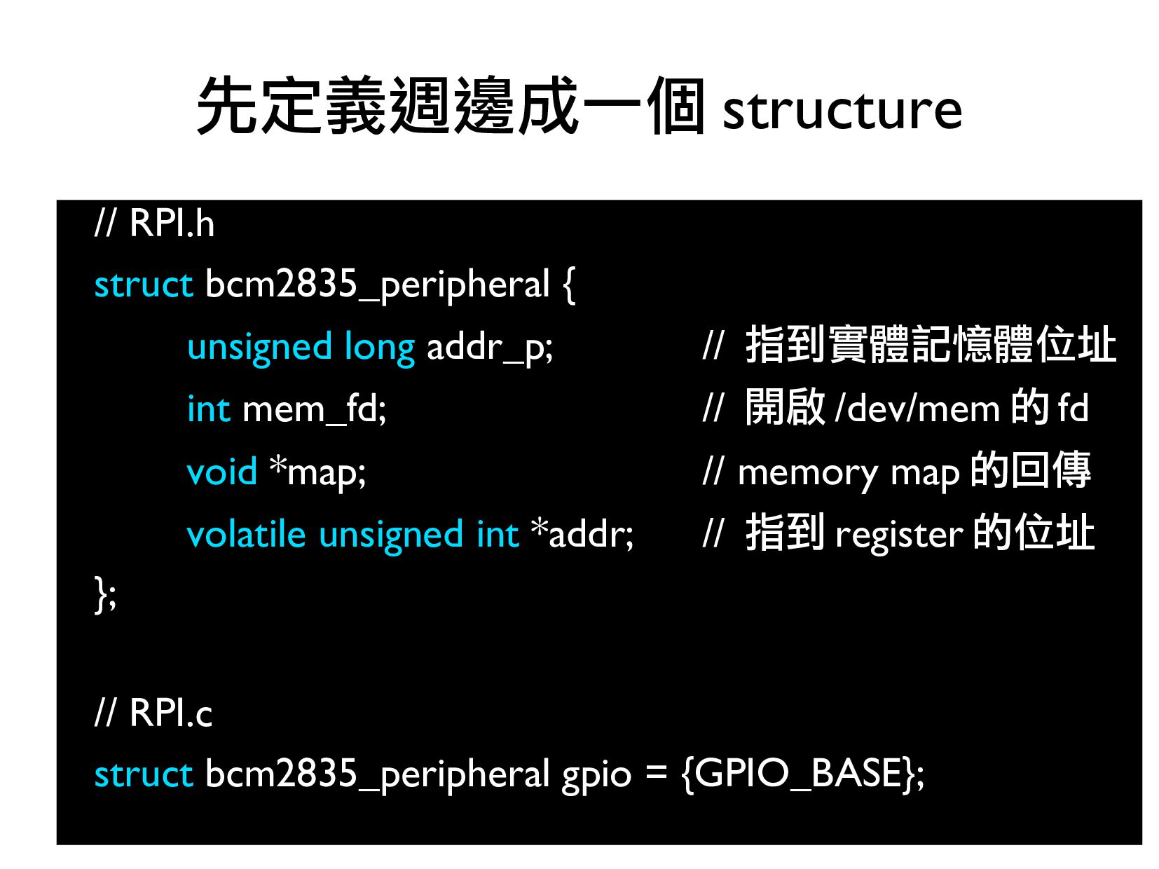
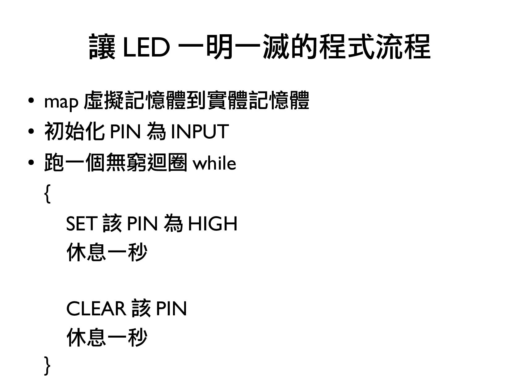
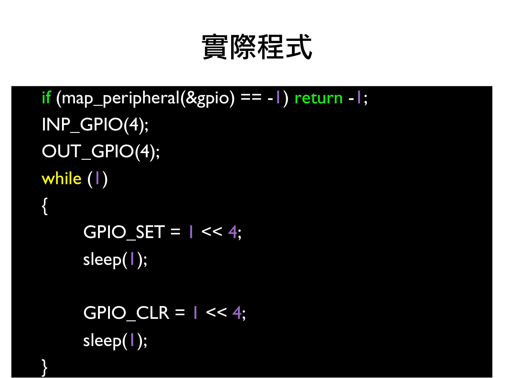
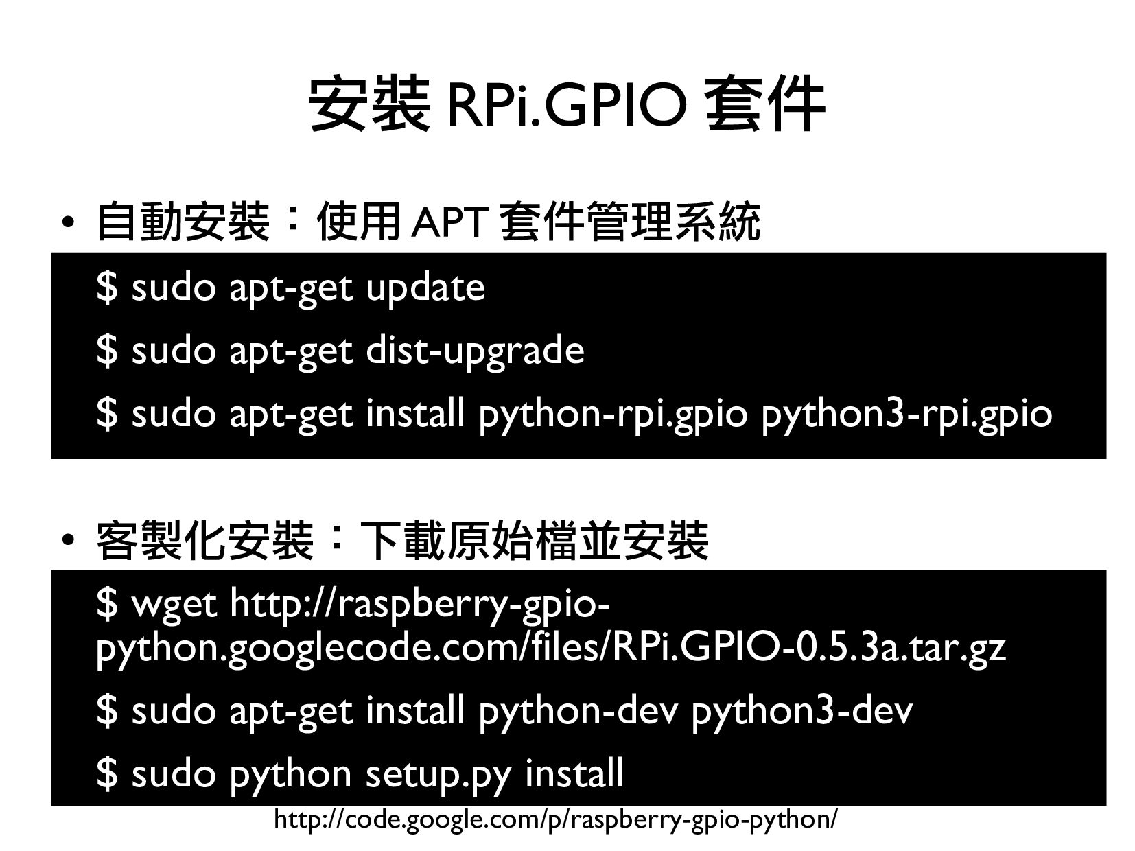
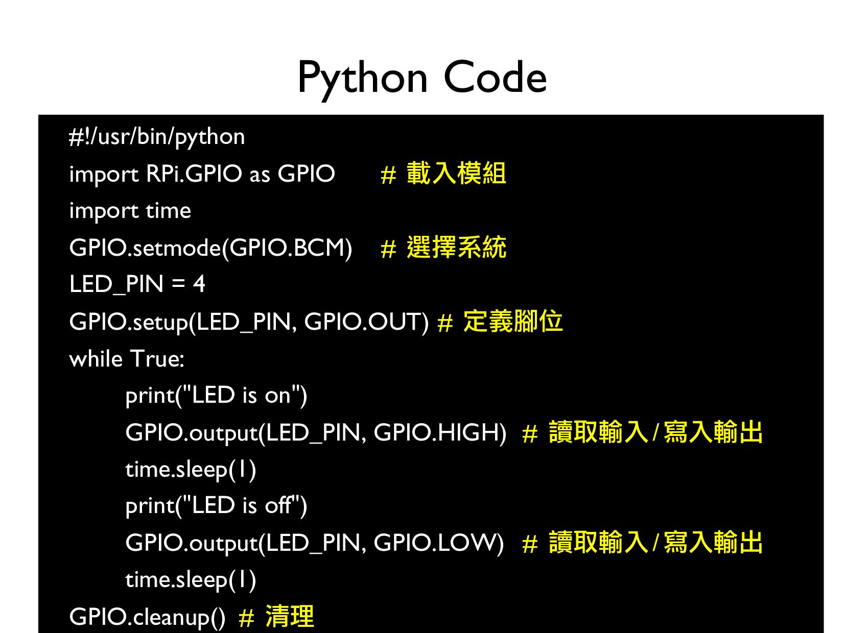
This slide demo the procedure to control Raspberry Pi GPIO with BCM2835 ARM Peripheral document

台灣樹莓派

December 19, 2013
Tweet

More Decks by 台灣樹莓派

Other Decks in Technology

Transcript

  1. • Element14 指定台灣地區 Raspberry Pi 獨家經銷商 • 專注於 Raspberry Pi

    應用與推廣 • Maker Faire 2013, 2013 科學玩意節 • 舉辦台灣第一次 Raspberry Pi 社群聚會 關於台灣樹莓派
  2. • A generic pin on an IC General Purpose Input

    Output(GPIO) http://raspberrypihobbyist.blogspot.tw/2012/09/so-many-inputs-so-few-gpio-pins.html
  3. • 開啟或關閉 GPIO • 決定是 0 激活還是 1 要激活 •

    決定是輸入還是輸出 • 寫值到某根腳位 • 從某根腳位讀值 • 決定是正緣觸發還是負緣觸發 • 等待中斷 (interrupt) 的發生 那軟體做什麼 ?
  4. • 深入 • 用 C 控制 GPIO • 淺出 •

    用 Python 控制 GPIO 深入淺出 GPIO
  5. • Address 映射過程 • virtual address physical address bus address

    • Peripheral address 起始位址 • Physical addresses: 0x20000000 - 0x20FFFFFF • Bus address: 0x7E000000 - • 實際位址是多少 ? 查表可得知 Address Translation (Page 6)
  6. • 41 個 register, 每個 register 是 32bit • 起始位址

    : 0x7E200000 • 表畫錯了 • 勘誤可見 重點 http://goo.gl/msNCRO
  7. // RPI.h #define BCM2708_PERI_BASE 0x20000000 • #define GPIO_BASE \ •

    (BCM2708_PERI_BASE + 0x200000) Address 映射結果
  8. 範例 1 : 將某根 PIN 腳 (g=4) 設成 INPUT 註

    :BCM2835 的 4 號腳位對應到實體腳位 7
  9. 1. 根據 g 找到對應的 GPFSEL table 2. 根據 g 取得對應到的

    FSEL 起始位置 3. 查表決定 FSEL 的 bit 值設定 處理步驟
  10. 每十個 Function Select 為一張表 (g)%10 : 取得第 1 張 GPFSEL

    table 1. 根據 g 找到對應的 GPFSEL table GPIO Register Assignment GPIO Alternate function select register 0
  11. ((g)%10)*3 : 取得第 4 個 FSEL 起始位置 2. 根據 g

    取得對應到的 FSEL 起始位置 GPIO Alternate function select register 0
  12. 000 表示 INPUT • 將 000 寫到原 register 中第 12-14

    個 bit 3. 查表決定 FSEL 的 bit 值設定
  13. 原 : xxxxxxxxxxxxxxxxxxxxxxxxxxxxxxxx (32-bit) &= ~(7<<(((g)%10)*3))) (4%10)*3 : 找第 12

    個 bit 7 << 12 : 將 111 左移 12 位 Bitwise 運算 , g=4
  14. 原 : xxxxxxxxxxxxxxxxxxxxxxxxxxxxxxxx (32-bit) &= ~(7<<(((g)%10)*3))) (4%10)*3 : 找第 12

    個 bit 7 << 12 : 將 111 左移 12 位 00000000000000000111000000000000 (NOT 運算 ) Bitwise 運算 , g=4
  15. 原 : xxxxxxxxxxxxxxxxxxxxxxxxxxxxxxxx (32-bit) &= ~(7<<(((g)%10)*3))) (4%10)*3 : 找第 12

    個 bit 7 << 12 : 將 111 左移 12 位 00000000000000000111000000000000 (NOT 運算 ) 11111111111111111000111111111111 ( 運算結果 ) Bitwise 運算 , g=4
  16. 原 : xxxxxxxxxxxxxxxxxxxxxxxxxxxxxxxx (32-bit) &= ~(7<<(((g)%10)*3))) (4%10)*3 : 找第 12

    個 bit 7 << 12 : 將 111 左移 12 位 00000000000000000111000000000000 (NOT 運算 ) 11111111111111111000111111111111 ( 運算結果 ) 原 : xxxxxxxxxxxxxxxxxxxxxxxxxxxxxxxx Bitwise 運算 , g=4
  17. 原 : xxxxxxxxxxxxxxxxxxxxxxxxxxxxxxxx (32-bit) &= ~(7<<(((g)%10)*3))) (4%10)*3 : 找第 12

    個 bit 7 << 12 : 將 111 左移 12 位 00000000000000000111000000000000 (NOT 運算 ) 11111111111111111000111111111111 ( 運算結果 ) 原 : xxxxxxxxxxxxxxxxxxxxxxxxxxxxxxxx 寫 : 11111111111111111000111111111111 (AND 運 算 ) Bitwise 運算 , g=4
  18. 原 : xxxxxxxxxxxxxxxxxxxxxxxxxxxxxxxx (32-bit) &= ~(7<<(((g)%10)*3))) (4%10)*3 : 找第 12

    個 bit 7 << 12 : 將 111 左移 12 位 00000000000000000111000000000000 (NOT 運算 ) 11111111111111111000111111111111 ( 運算結果 ) 原 : xxxxxxxxxxxxxxxxxxxxxxxxxxxxxxxx 寫 : 11111111111111111000111111111111 (AND 運算 ) 新 : xxxxxxxxxxxxxxxxx000xxxxxxxxxxxx ( 運算結果 ) Bitwise 運算 , g=4
  19. 001 表示 INPUT • 將 001 寫到原 register 中第 12-14

    個 bit 查表決定 FSEL 的 bit 值設定
  20. 原 : xxxxxxxxxxxxxxxxxxxxxxxxxxxxxxxx (32-bit) |= (1<<(((g)%10)*3))) (4%10)*3 : 找第 12

    個 bit 1 << 12 : 將 001 左移 12 位 原 : xxxxxxxxxxxxxxxxxxxxxxxxxxxxxxxx 寫 : 00000000000000000001000000000000 (OR 運算 ) 新 : xxxxxxxxxxxxxxxxxxx1xxxxxxxxxxxx ( 結果 ) Bitwise 運算 , g=4
  21. • 0 - 31 號 Pin 都是看 GPSET0 • 寫入

    1 表示 Set, 寫入 0 無效果 查表決定 GPSETn 的 bit 值設定 Page 95
  22. • 0 - 31 號 Pin 都是看 GPCLR0 • 寫入

    1 表示 Clear, 寫入 0 無效果 查表決定 GPCLRn 的 bit 值設定 Page 95
  23. // RPI.h struct bcm2835_peripheral { unsigned long addr_p; // 指到實體記憶體位址

    int mem_fd; // 開啟 /dev/mem 的 fd void *map; // memory map 的回傳 volatile unsigned int *addr; // 指到 register 的位址 }; // RPI.c struct bcm2835_peripheral gpio = {GPIO_BASE}; 先定義週邊成一個 structure
  24. • map 虛擬記憶體到實體記憶體 • 初始化 PIN 為 INPUT • 跑一個無窮迴圈

    while { SET 該 PIN 為 HIGH 休息一秒 CLEAR 該 PIN 休息一秒 } 讓 LED 一明一滅的程式流程
  25. if (map_peripheral(&gpio) == -1) return -1; INP_GPIO(4); OUT_GPIO(4); while (1)

    { GPIO_SET = 1 << 4; sleep(1); GPIO_CLR = 1 << 4; sleep(1); } 實際程式
  26. • 自動安裝:使用 APT 套件管理系統 $ sudo apt-get update $ sudo

    apt-get dist-upgrade $ sudo apt-get install python-rpi.gpio python3-rpi.gpio • 客製化安裝:下載原始檔並安裝 $ wget http://raspberry-gpio- python.googlecode.com/files/RPi.GPIO-0.5.3a.tar.gz $ sudo apt-get install python-dev python3-dev $ sudo python setup.py install 安裝 RPi.GPIO 套件 http://code.google.com/p/raspberry-gpio-python/
  27. • 載入模組 (Import module) • 選擇系統 (Define pin numbering) •

    定義腳位 (Setup up a channel) • 讀取輸入 / 寫入輸出 (Input/Output) • 清理 (Cleanup) Python Code http://code.google.com/p/raspberry-gpio-python/wiki/BasicUsage
  28. #!/usr/bin/python import RPi.GPIO as GPIO # 載入模組 import time GPIO.setmode(GPIO.BCM)

    # 選擇系統 LED_PIN = 4 GPIO.setup(LED_PIN, GPIO.OUT) # 定義腳位 while True: print("LED is on") GPIO.output(LED_PIN, GPIO.HIGH) # 讀取輸入/寫入輸出 time.sleep(1) print("LED is off") GPIO.output(LED_PIN, GPIO.LOW) # 讀取輸入/寫入輸出 time.sleep(1) GPIO.cleanup() # 清理 Python Code
  29. • RPi Low-level peripherals • http://elinux.org/RPi_Low-level_peripherals • Raspberry Pi |

    Wiring | Gordons Projects • https://projects.drogon.net/raspberry-pi/wiringpi/ • Low Level Programming of the Raspberry Pi in C • http://www.pieter-jan.com/node/15 參考資料