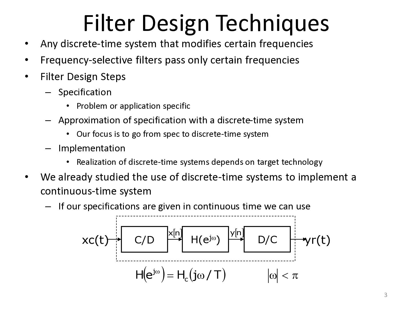
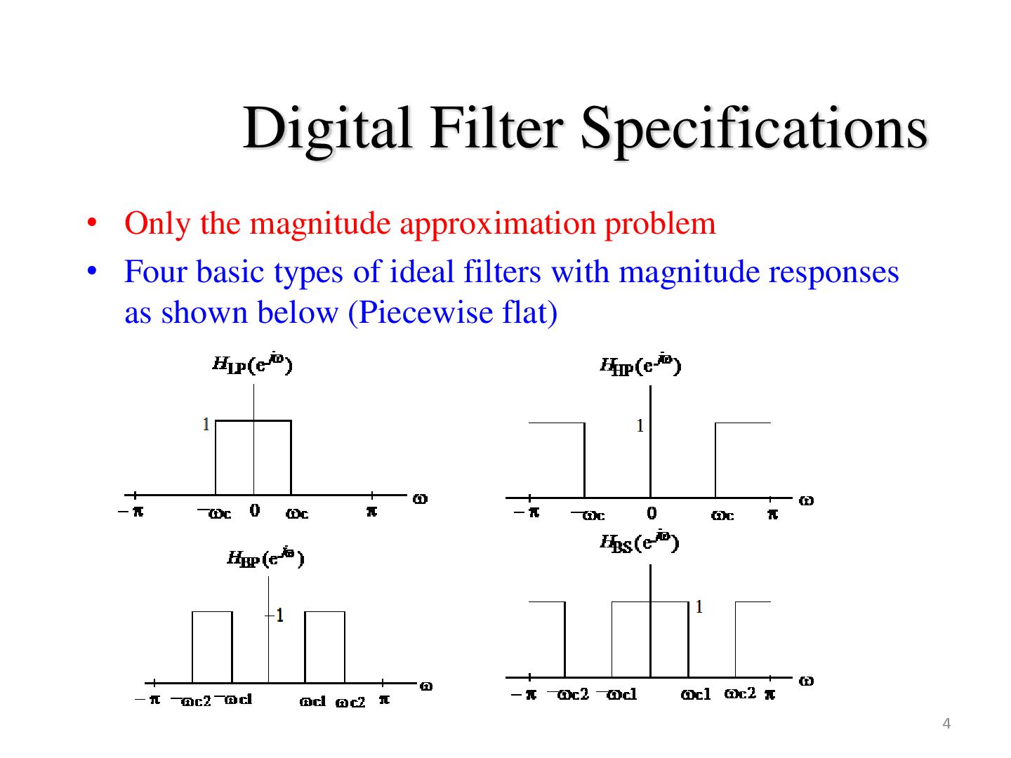
modifies certain frequencies Frequency-selective filters pass only certain frequencies Filter Design Steps – Specification • Problem or application specific – Approximation of specification with a discrete-time system • Our focus is to go from spec to discrete-time system – Implementation • Realization of discrete-time systems depends on target technology • We already studied the use of discrete-time systems to implement a continuous-time system – If our specifications are given in continuous time we can use xc(t) C/D xn H(ej) H ej Hc j / T yn D/C yr(t) 3
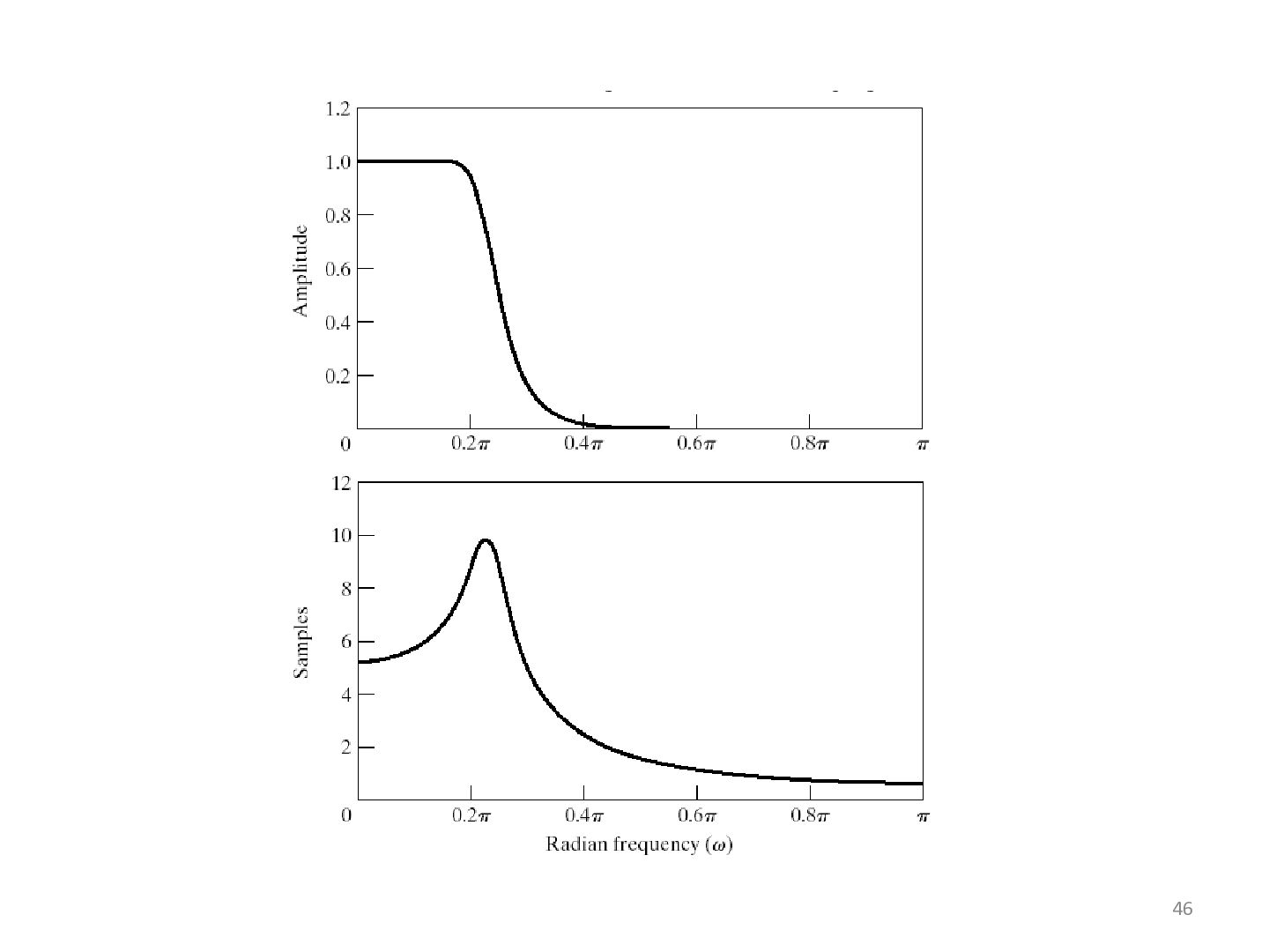
of the following is sufficient) – their impulse responses infinitely long noncausal – Their amplitude responses cannot be equal to a constant over a band of frequencies Another perspective that provides some understanding can be obtained by looking at the ideal amplitude squared. 5
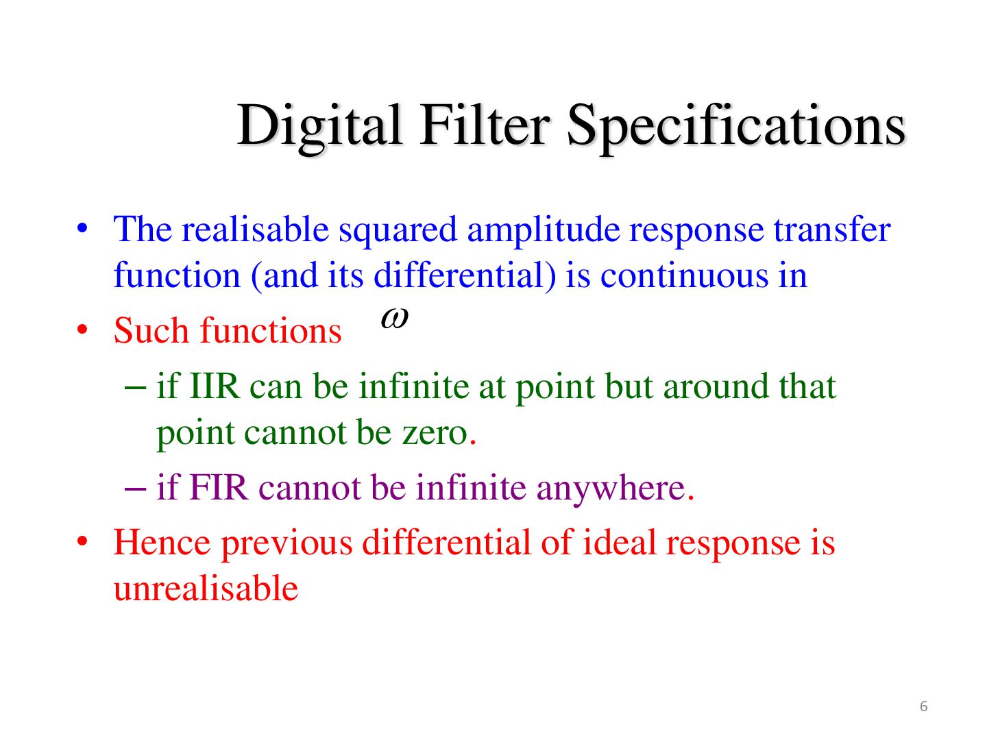
function (and its differential) is continuous in • Such functions – if IIR can be infinite at point but around that point cannot be zero. – if FIR cannot be infinite anywhere. • Hence previous differential of ideal response is unrealisable 6
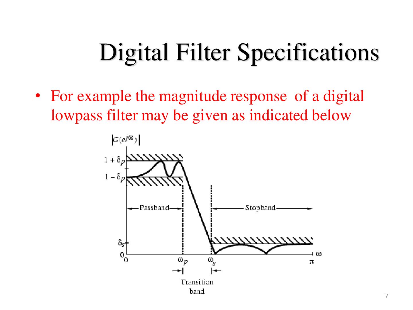
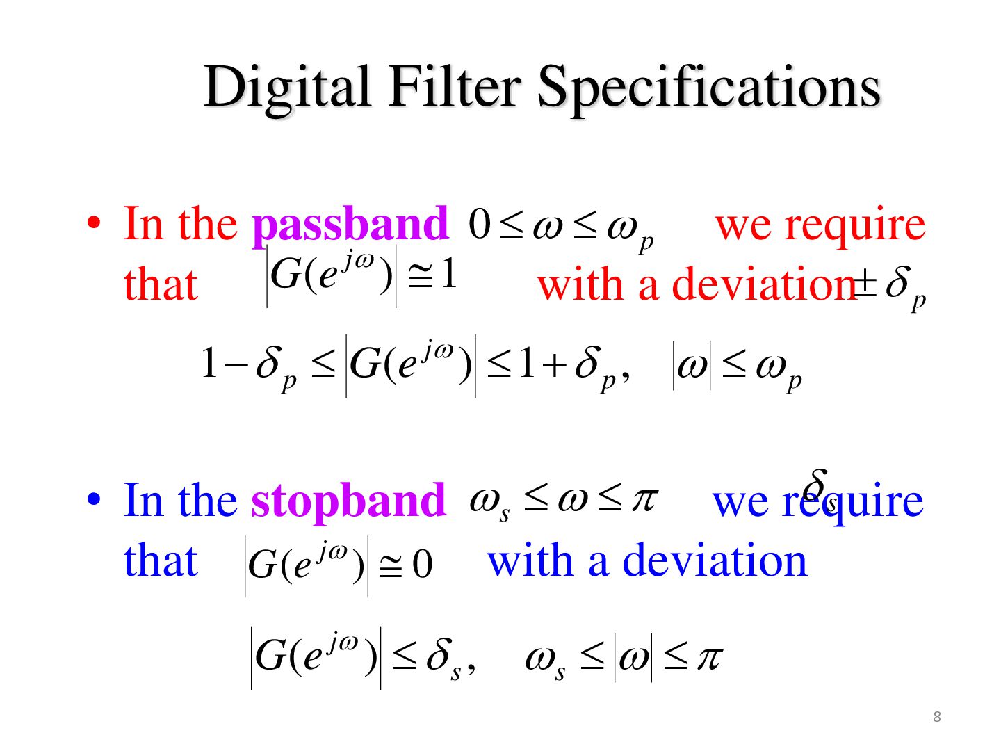
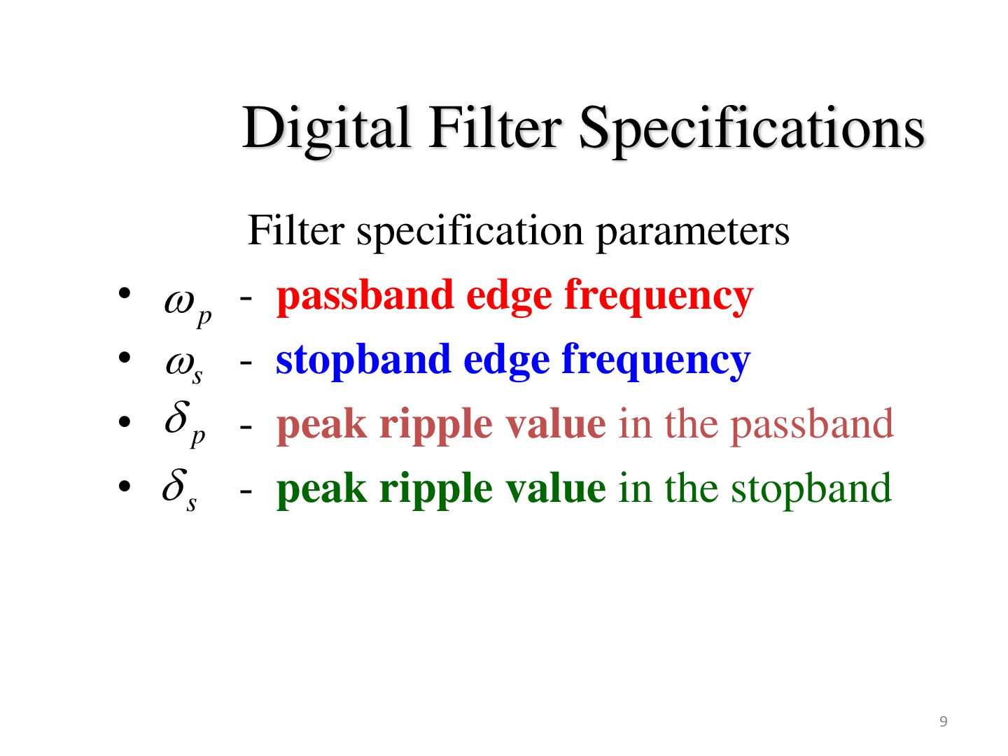
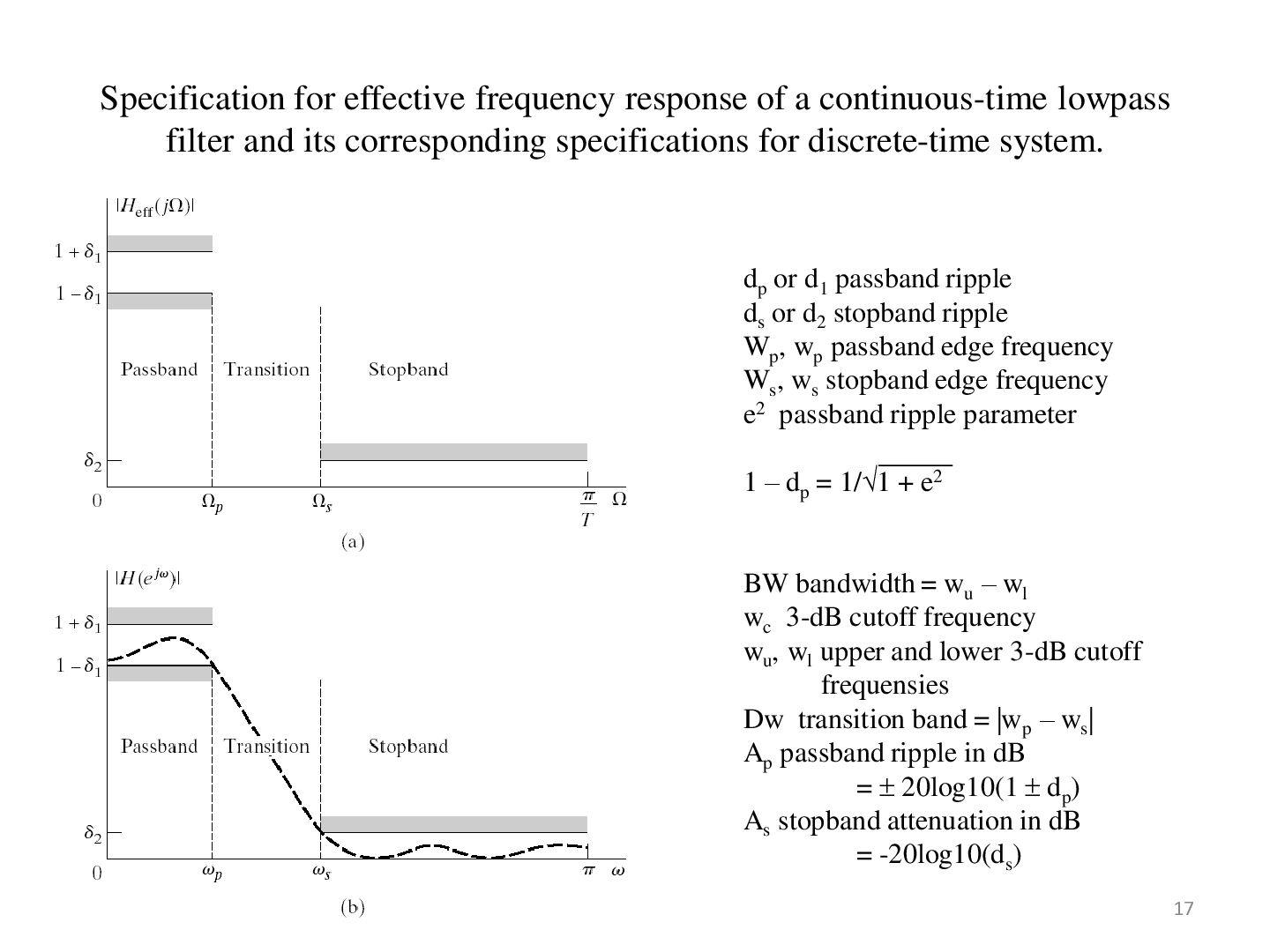
p we require j G ( e ) 1 that with a deviation p 1 p G(e j ) 1 p , p s • In the stopband s we require that G (e j ) 0 with a deviation j G (e ) s , s 8
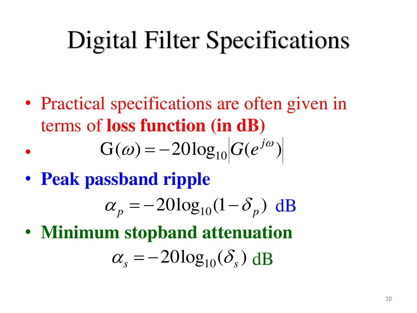
terms of loss function (in dB) j G ( ) 20 log G ( e ) • 10 • Peak passband ripple p 20 log10 (1 p ) dB • Minimum stopband attenuation s 20 log10 ( s ) dB 10
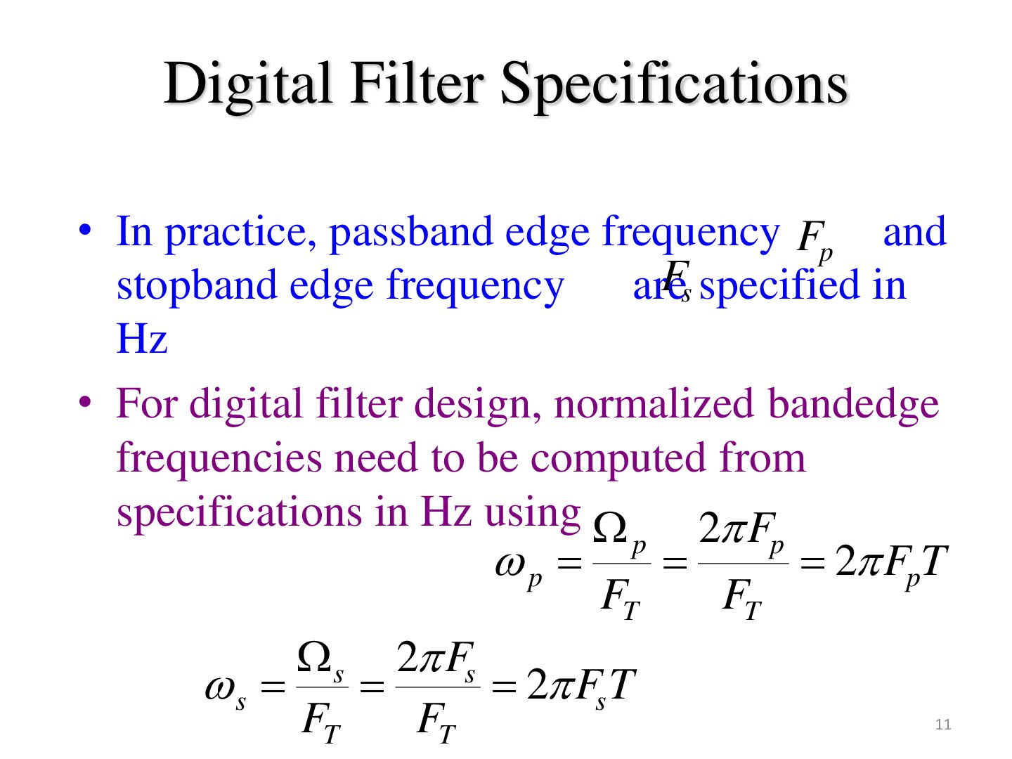
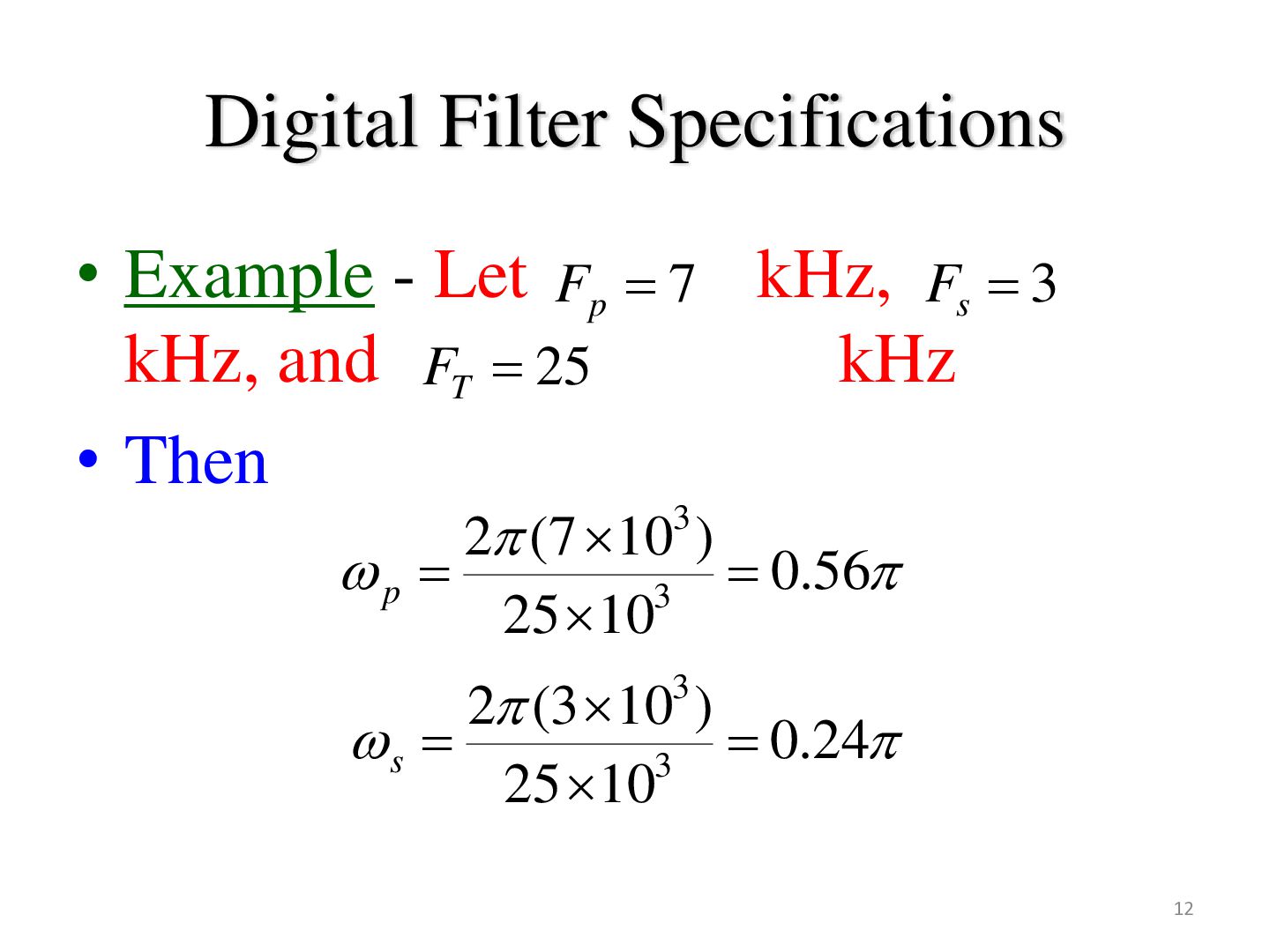
and Fs specified in stopband edge frequency are Hz • For digital filter design, normalized bandedge frequencies need to be computed from specifications in Hz using 2 Fp p p 2 FpT FT FT s 2 Fs s 2 Fs T FT FT 11
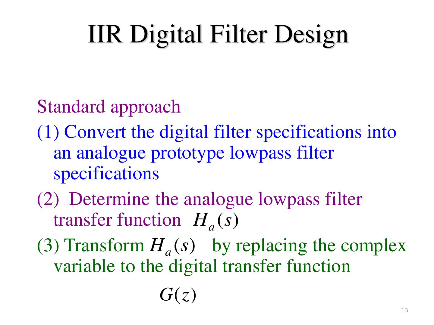
filter specifications into an analogue prototype lowpass filter specifications (2) Determine the analogue lowpass filter transfer function H a (s) (3) Transform H a (s) by replacing the complex variable to the digital transfer function G (z ) 13
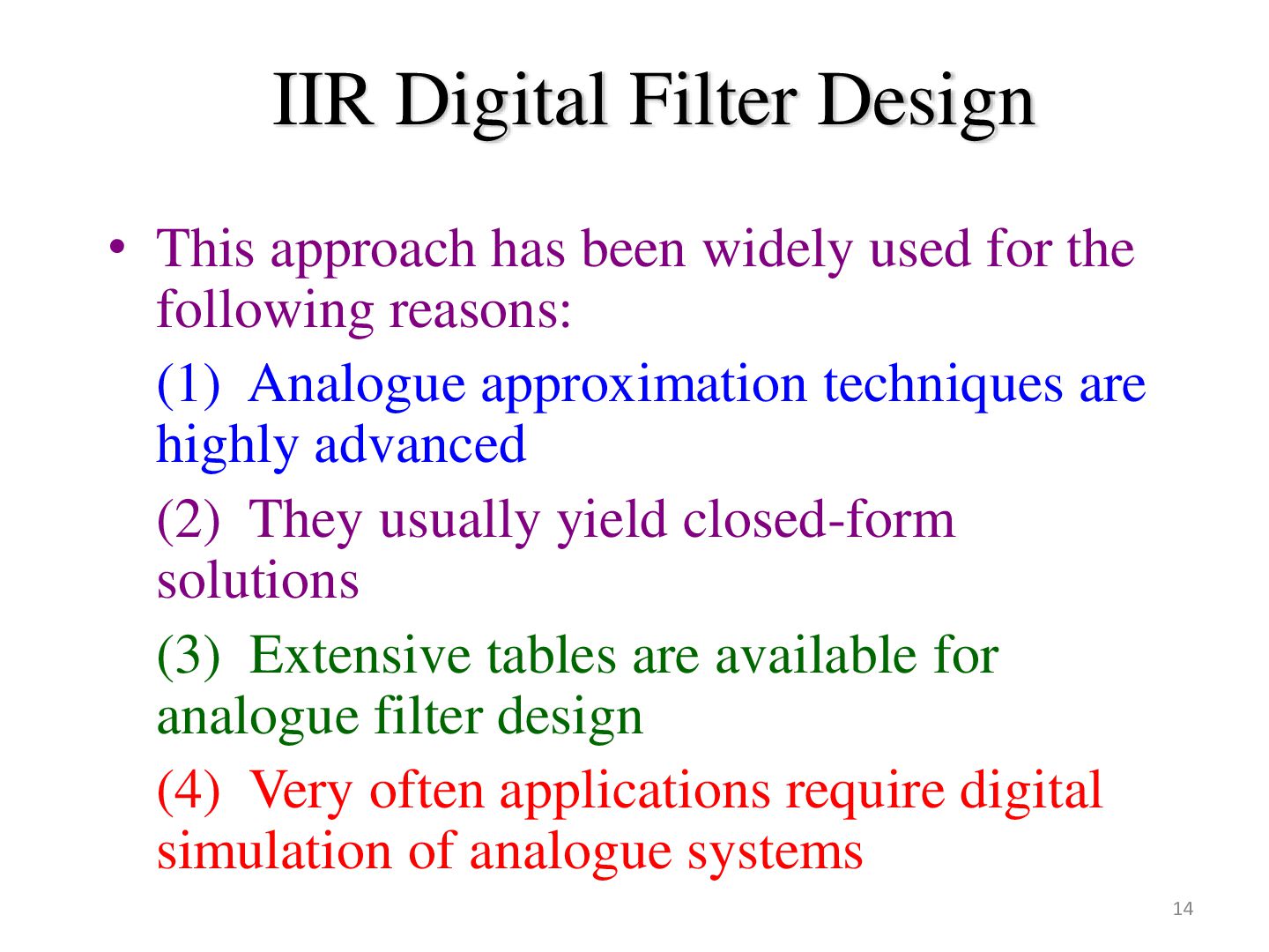
used for the following reasons: (1) Analogue approximation techniques are highly advanced (2) They usually yield closed-form solutions (3) Extensive tables are available for analogue filter design (4) Very often applications require digital simulation of analogue systems 14
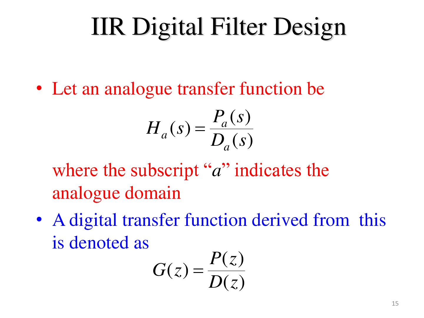
be Pa ( s ) H a (s) Da ( s ) where the subscript “a” indicates the analogue domain • A digital transfer function derived from this is denoted as P( z ) G( z) D( z ) 15
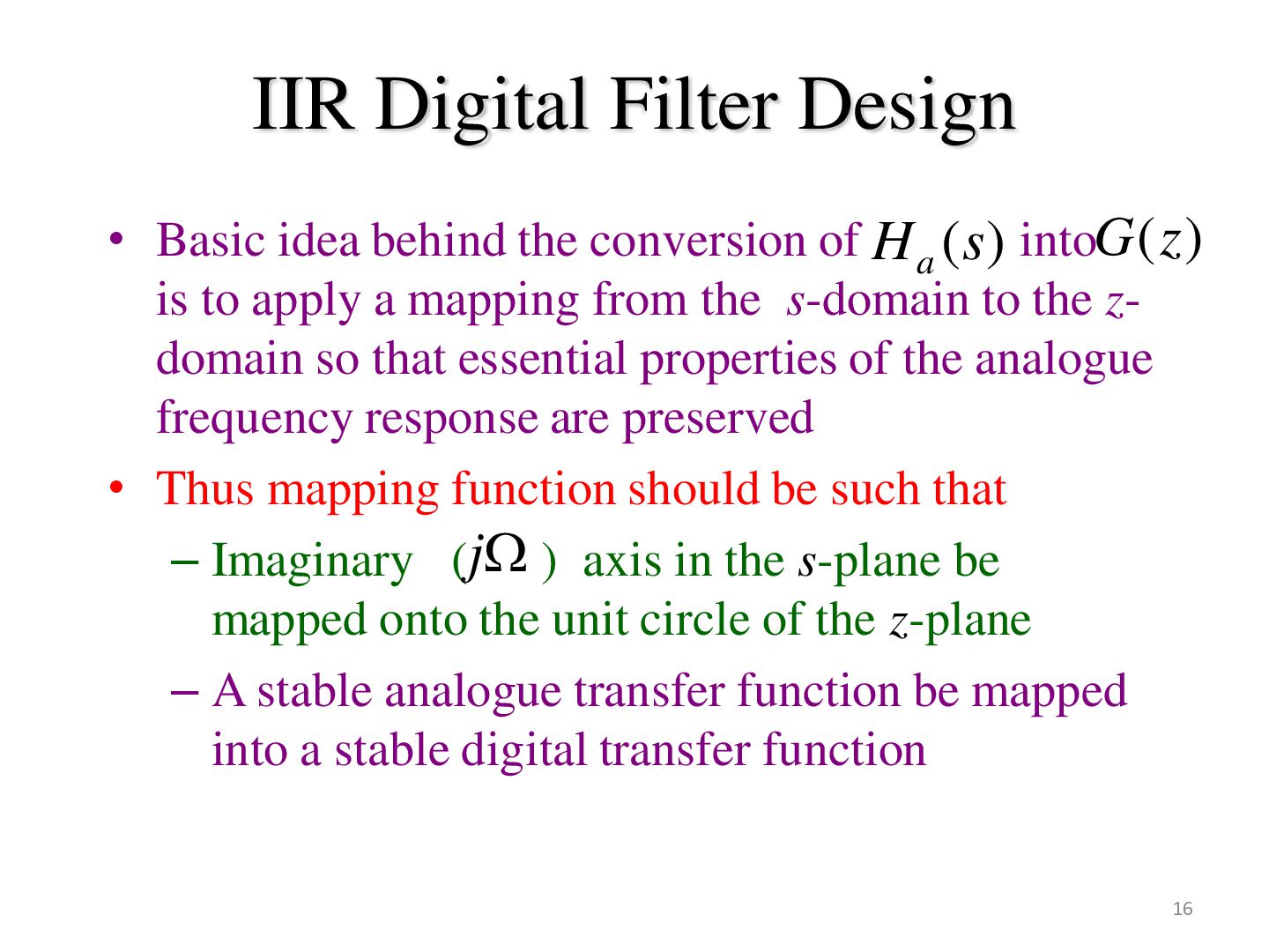
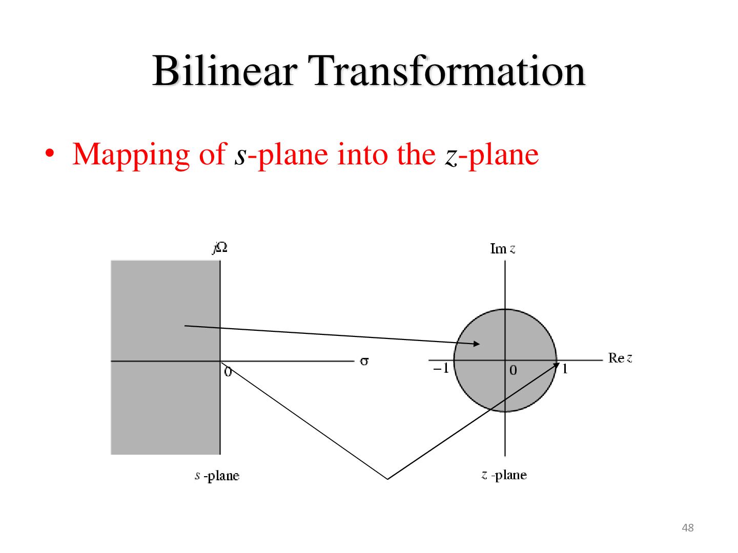
of H a (s) intoG (z ) is to apply a mapping from the s-domain to the zdomain so that essential properties of the analogue frequency response are preserved • Thus mapping function should be such that – Imaginary (j ) axis in the s-plane be mapped onto the unit circle of the z-plane – A stable analogue transfer function be mapped into a stable digital transfer function 16
• The art of continuous-time IIR filter design is highly advanced and, since useful results can be achieved, it is advantageous to use the design procedures already developed for continuous-time filters. • Many useful continuous-time IIR design methods have relatively simple closed-form design formulas. Therefore, discrete-time IIR filter design methods based on such standard continuous-time design formulas are rather simple to carry out. • The standard approximation methods that work well for continuoustime IIR filters do not lead to simple closed-form design formulas when these methods are applied directly to the discrete-time IIR case. 19
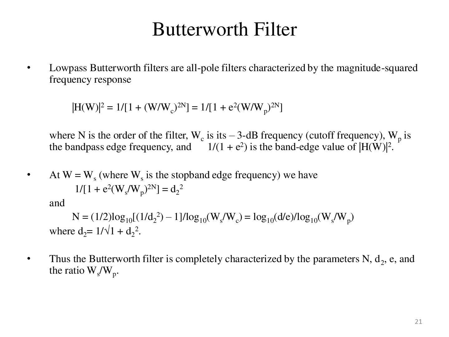
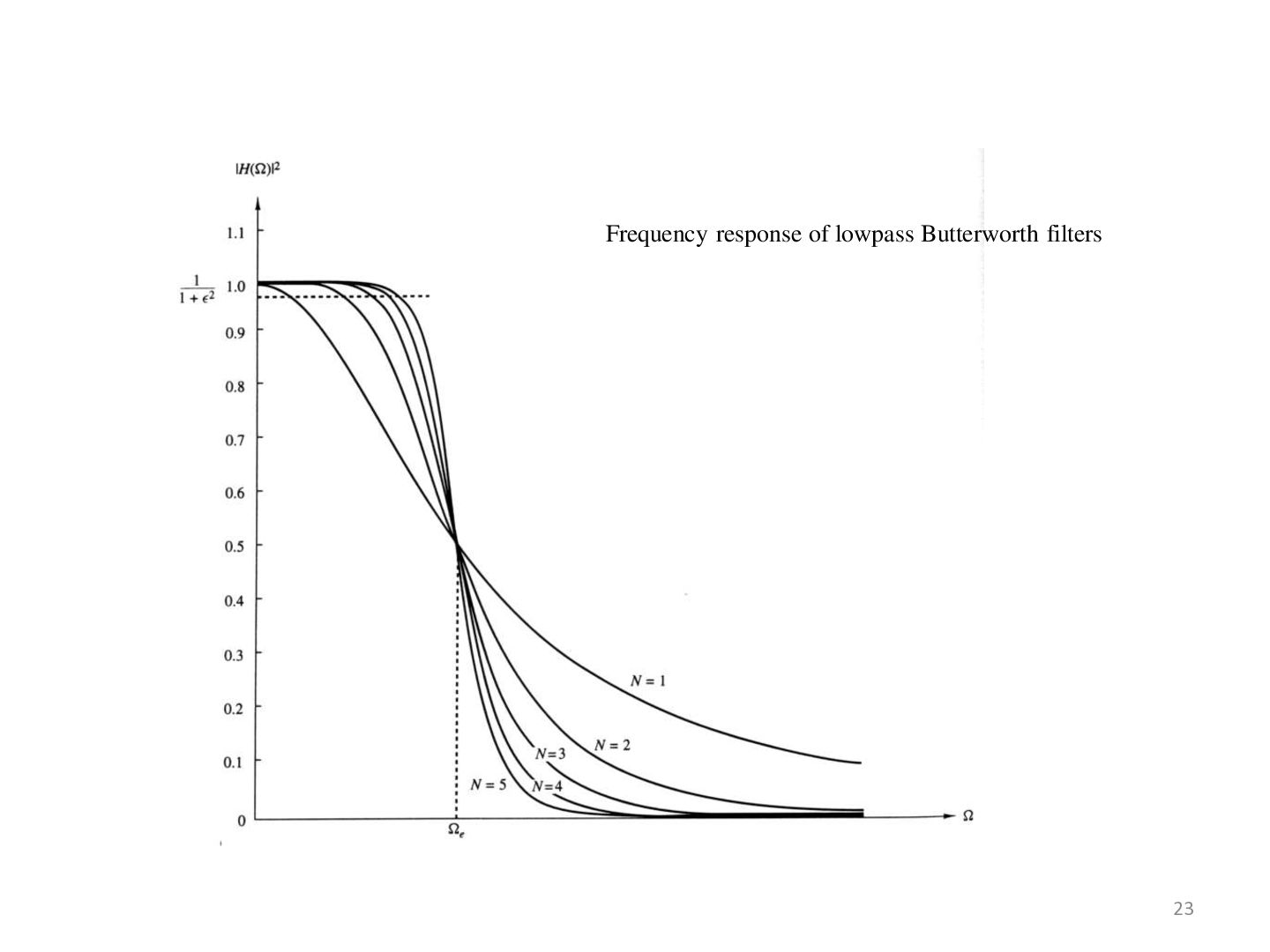
by the magnitude-squared frequency response |H(W)|2 = 1/[1 + (W/Wc)2N] = 1/[1 + e2(W/Wp)2N] where N is the order of the filter, Wc is its – 3-dB frequency (cutoff frequency), Wp is the bandpass edge frequency, and 1/(1 + e2) is the band-edge value of |H(W)|2. • At W = Ws (where Ws is the stopband edge frequency) we have 1/[1 + e2(Ws/Wp)2N] = d22 and N = (1/2)log10[(1/d22) – 1]/log10(Ws/Wc) = log10(d/e)/log10(Ws/Wp) where d2= 1/1 + d22. • Thus the Butterworth filter is completely characterized by the parameters N, d 2, e, and the ratio Ws/Wp. 21
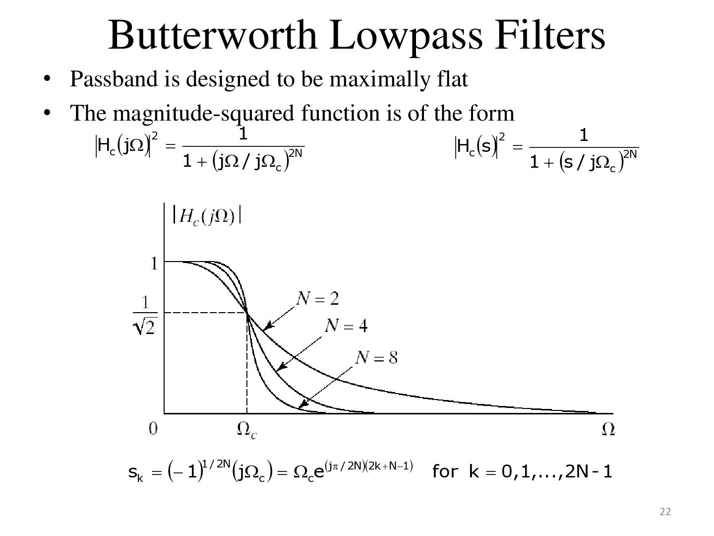
flat • The magnitude-squared function is of the form 2 1 2 1 Hc j H s c 2N 2N 1 j / jc 1 s / jc sk 1 1 / 2N jc cej / 2N2k N1 for k 0,1,...,2N - 1 22
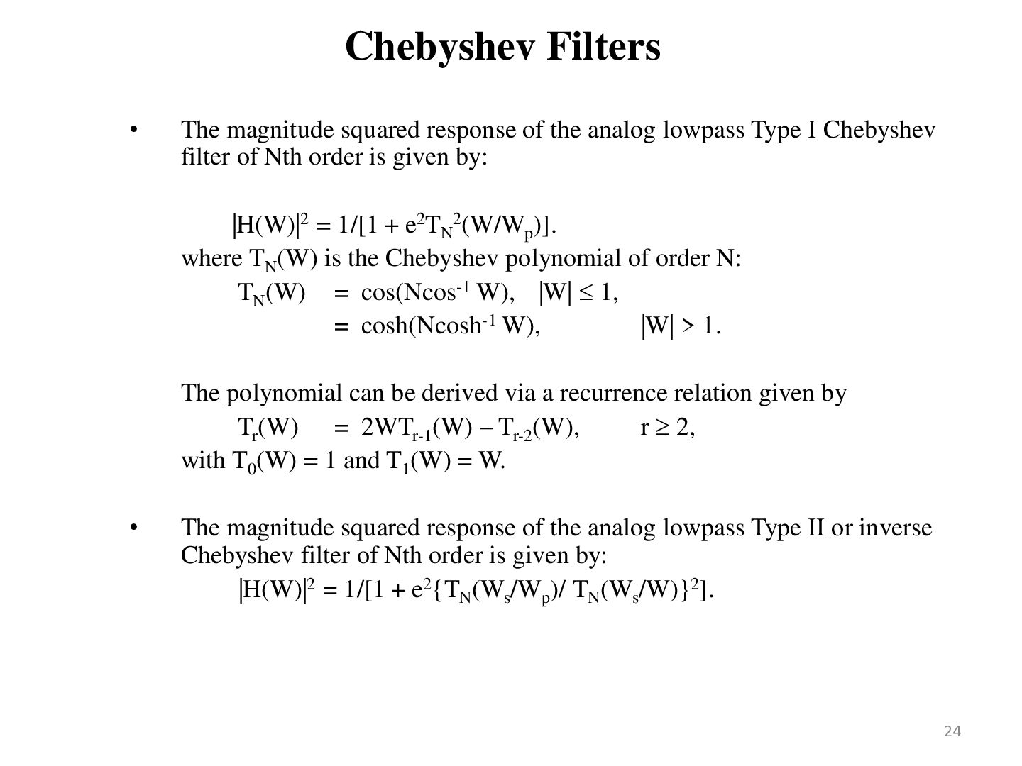
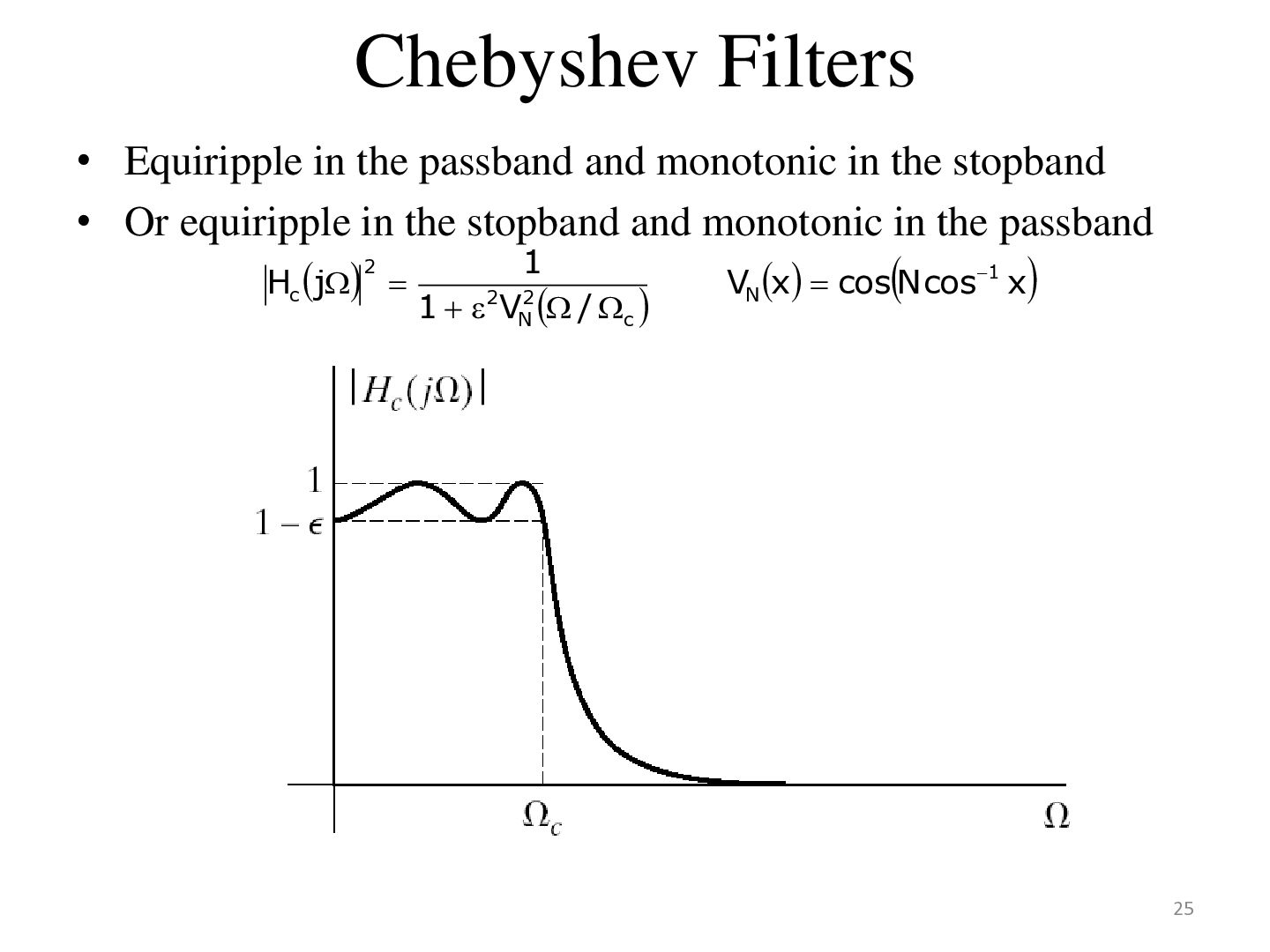
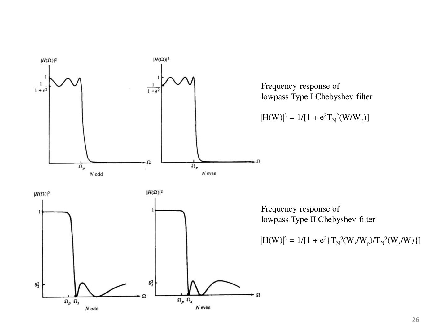
lowpass Type I Chebyshev filter of Nth order is given by: |H(W)|2 = 1/[1 + e2TN2(W/Wp)]. where TN(W) is the Chebyshev polynomial of order N: TN(W) = cos(Ncos-1 W), |W| 1, = cosh(Ncosh-1 W), |W| > 1. The polynomial can be derived via a recurrence relation given by Tr(W) = 2WTr-1(W) – Tr-2(W), r 2, with T0(W) = 1 and T1(W) = W. • The magnitude squared response of the analog lowpass Type II or inverse Chebyshev filter of Nth order is given by: |H(W)|2 = 1/[1 + e2{TN(Ws/Wp)/ TN(Ws/W)}2]. 24
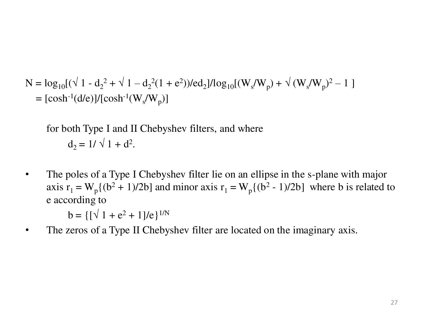
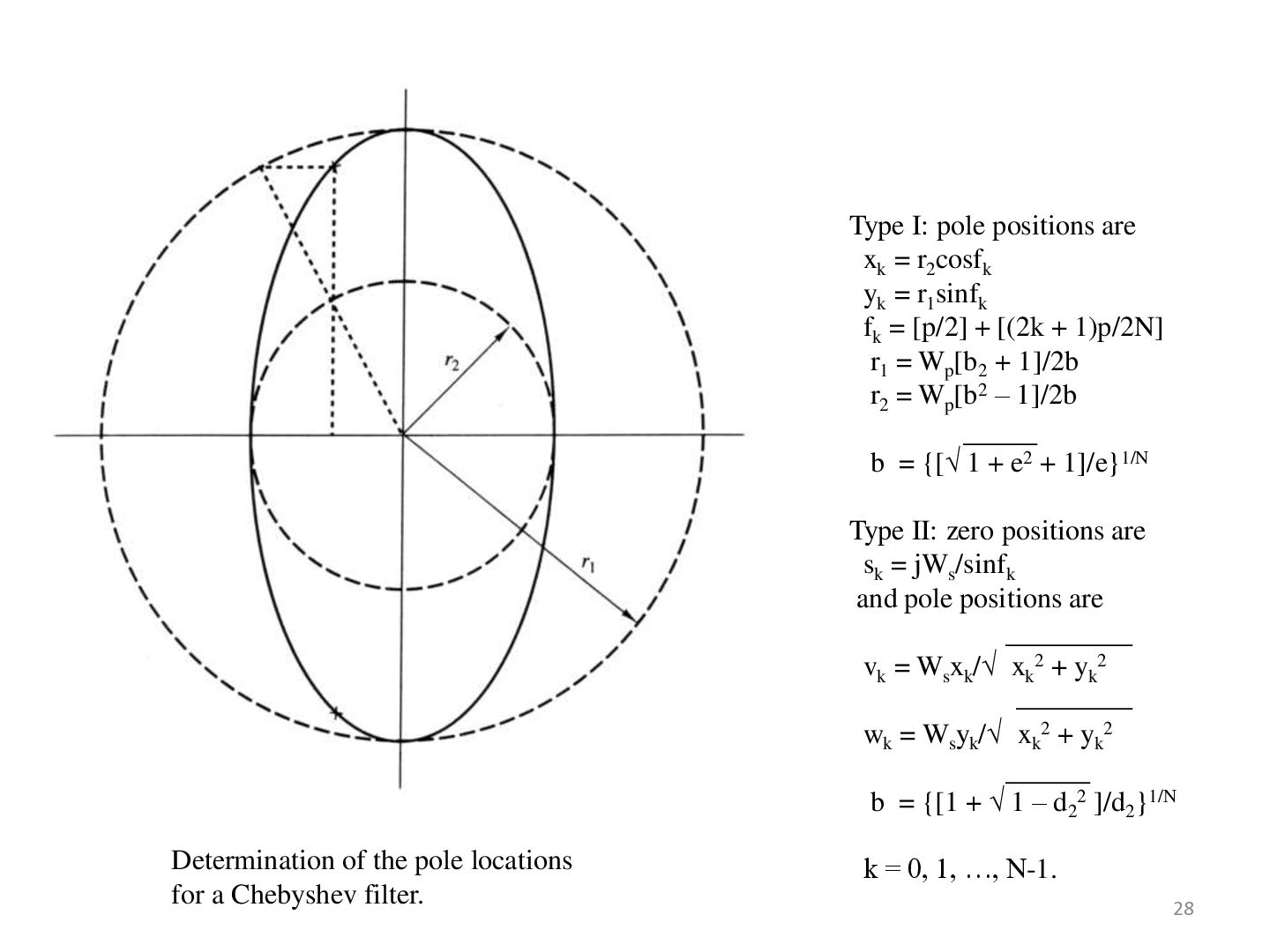
d22(1 + e2))/ed2]/log10[(Ws/Wp) + (Ws/Wp)2 – 1 ] = [cosh-1(d/e)]/[cosh-1(Ws/Wp)] for both Type I and II Chebyshev filters, and where d2 = 1/ 1 + d2. • • The poles of a Type I Chebyshev filter lie on an ellipse in the s-plane with major axis r1 = Wp{(b2 + 1)/2b] and minor axis r1 = Wp{(b2 - 1)/2b] where b is related to e according to b = {[ 1 + e2 + 1]/e}1/N The zeros of a Type II Chebyshev filter are located on the imaginary axis. 27
r1sinfk fk = [p/2] + [(2k + 1)p/2N] r1 = Wp[b2 + 1]/2b r2 = Wp[b2 – 1]/2b b = {[ 1 + e2 + 1]/e}1/N Type II: zero positions are sk = jWs/sinfk and pole positions are vk = Wsxk/ xk2 + yk2 wk = Wsyk/ xk2 + yk2 b = {[1 + 1 – d22 ]/d2}1/N Determination of the pole locations for a Chebyshev filter. k = 0, 1, …, N-1. 28
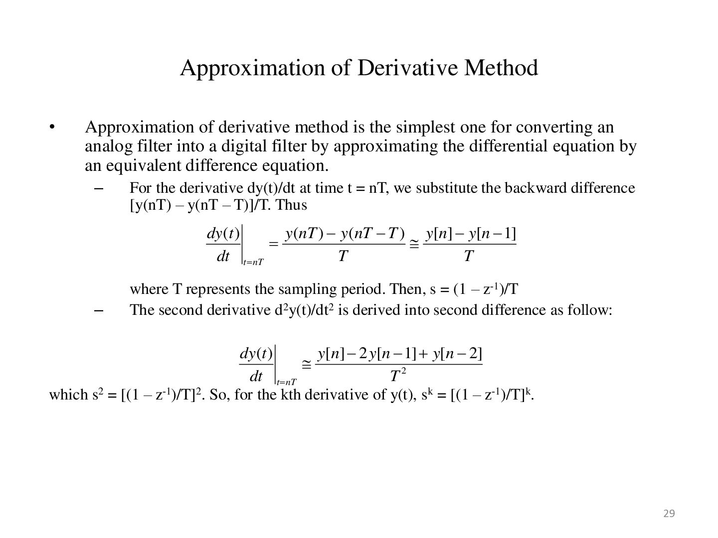
the simplest one for converting an analog filter into a digital filter by approximating the differential equation by an equivalent difference equation. – For the derivative dy(t)/dt at time t = nT, we substitute the backward difference [y(nT) – y(nT – T)]/T. Thus dy (t ) y (nT ) y (nT T ) y[n] y[n 1] dt t nT T T – where T represents the sampling period. Then, s = (1 – z-1)/T The second derivative d2y(t)/dt2 is derived into second difference as follow: dy(t ) y[n] 2 y[n 1] y[n 2] dt t nT T2 which s2 = [(1 – z-1)/T]2. So, for the kth derivative of y(t), sk = [(1 – z-1)/T]k. 29
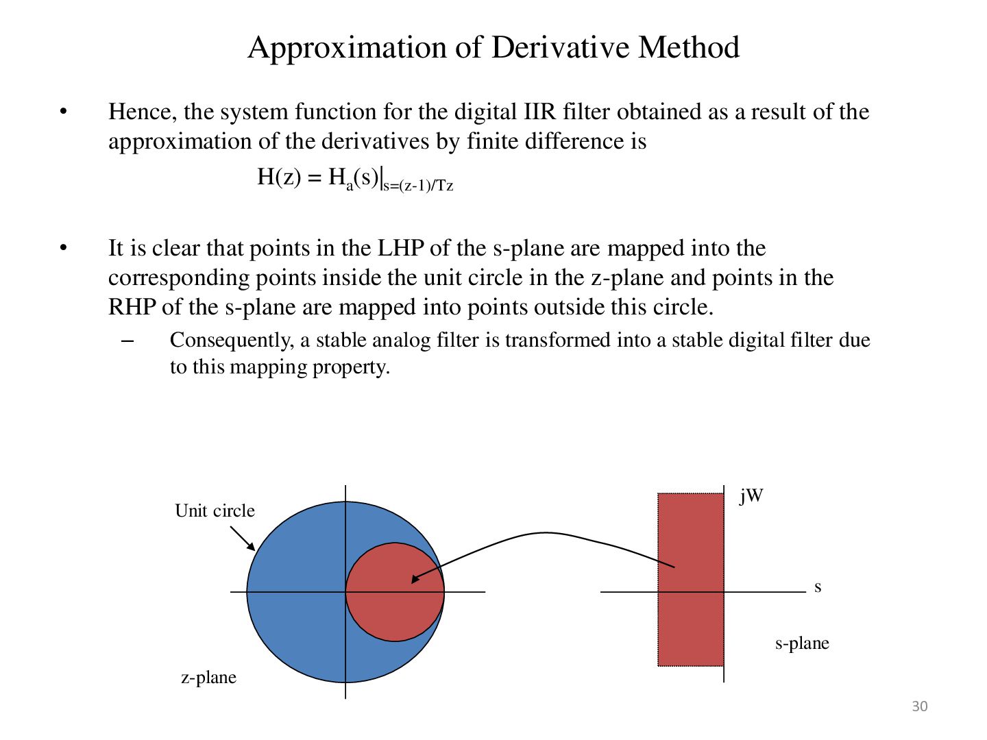
the digital IIR filter obtained as a result of the approximation of the derivatives by finite difference is H(z) = Ha(s)|s=(z-1)/Tz • It is clear that points in the LHP of the s-plane are mapped into the corresponding points inside the unit circle in the z-plane and points in the RHP of the s-plane are mapped into points outside this circle. – Consequently, a stable analog filter is transformed into a stable digital filter due to this mapping property. Unit circle jW s s-plane z-plane 30
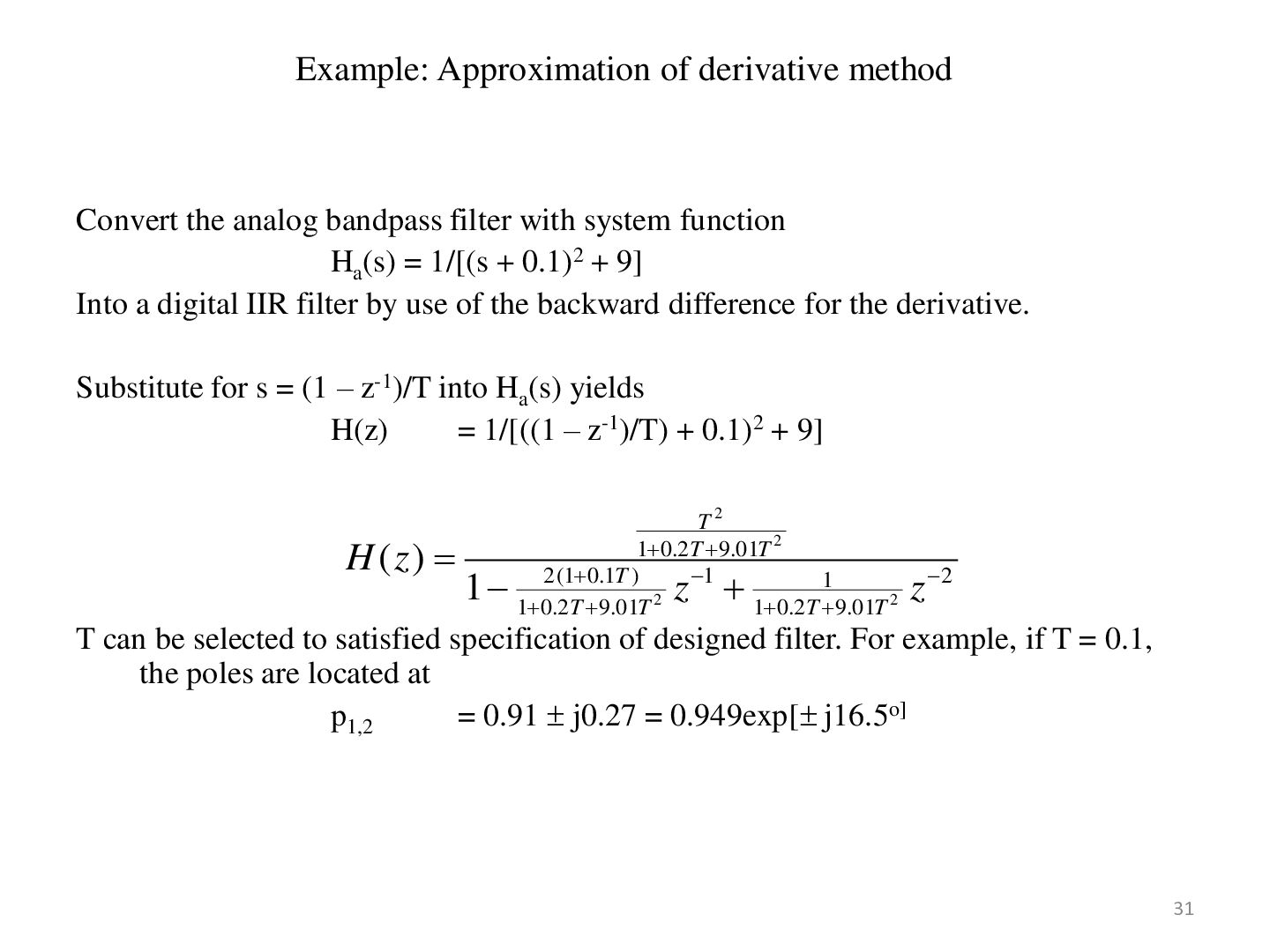
with system function Ha(s) = 1/[(s + 0.1)2 + 9] Into a digital IIR filter by use of the backward difference for the derivative. Substitute for s = (1 – z-1)/T into Ha(s) yields H(z) = 1/[((1 – z-1)/T) + 0.1)2 + 9] H ( z) 1 T2 1 0.2T 9.01T 2 1 2 (1 0.1T ) 1 2 1 0.2T 9.01T 1 0.2T 9.01T 2 z z 2 T can be selected to satisfied specification of designed filter. For example, if T = 0.1, the poles are located at p1,2 = 0.91 j0.27 = 0.949exp[ j16.5o] 31
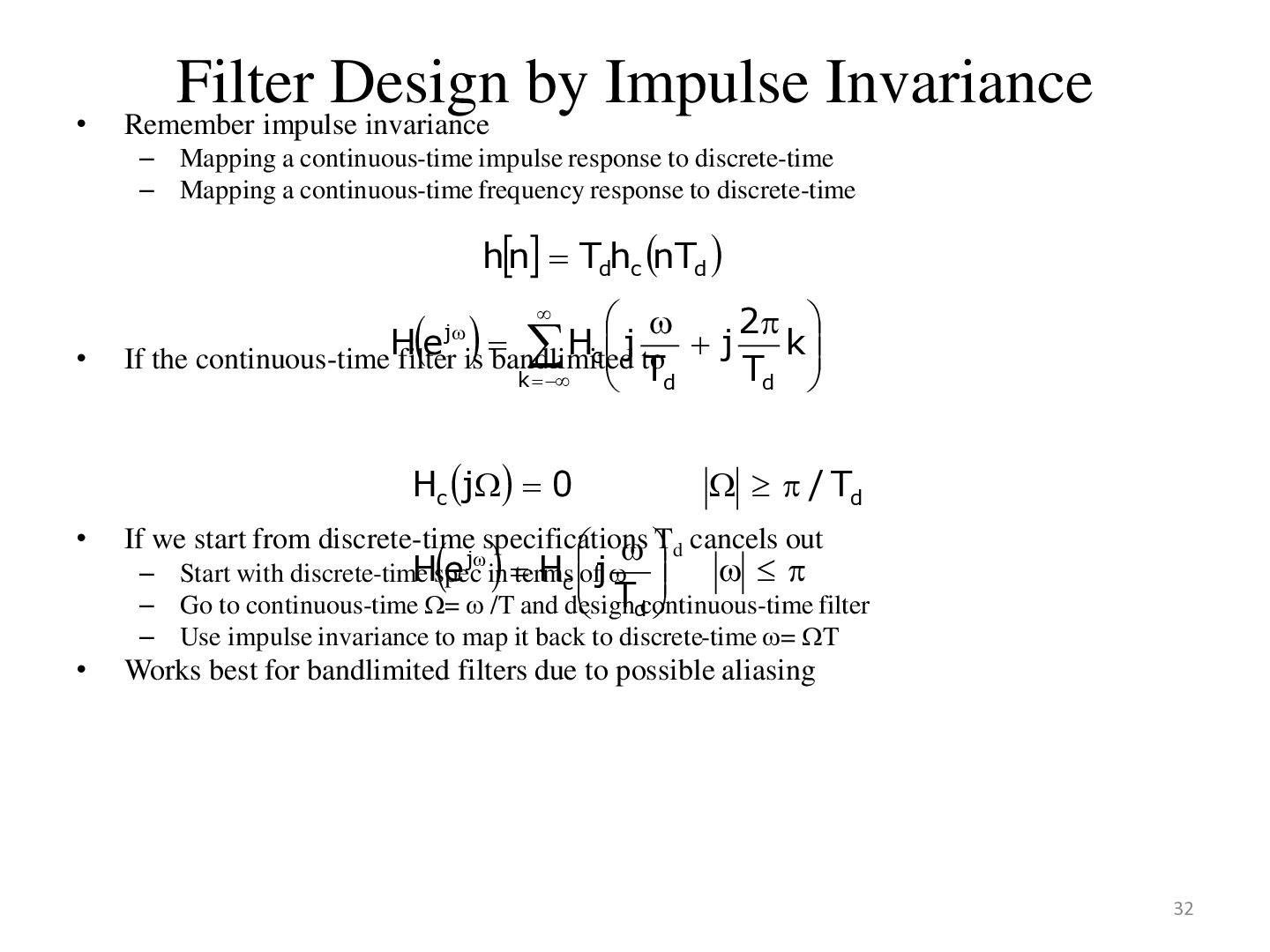
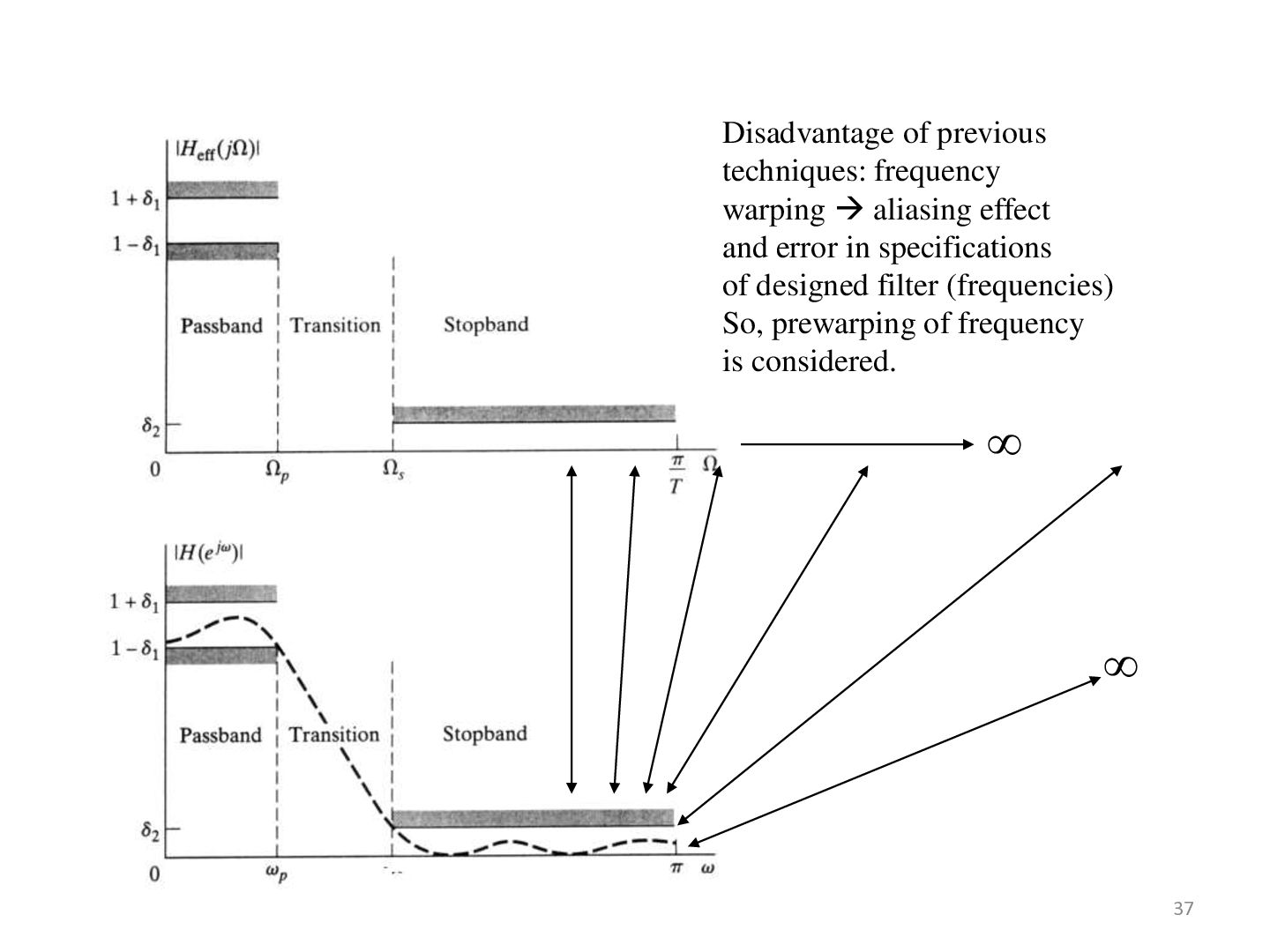
Mapping a continuous-time impulse response to discrete-time – Mapping a continuous-time frequency response to discrete-time hn Tdhc nTd • 2 e is bandlimited Hc j to j k If the continuous-timeH filter Td k Td j Hc j 0 / Td • If we start from discrete-time specifications Td cancels out • Works best for bandlimited filters due to possible aliasing Hspec e in terms Hc ofj – Start with discrete-time – Go to continuous-time = /T and design filter Tdcontinuous-time – Use impulse invariance to map it back to discrete-time = T j 32
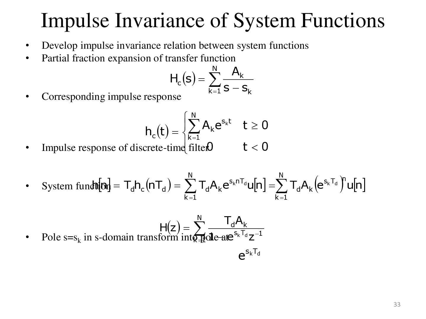
relation between system functions Partial fraction expansion of transfer function Ak k 1 s sk N Hc s • Corresponding impulse response • N Ak esk t hc t k 1 Impulse response of discrete-time filter0 N • hn Tdhc nTd TdAk e System function k 1 t0 t0 sknTd N un TdAk esk Td un n k 1 TdAk sk Td 1 Pole s=sk in s-domain transform intok pole z 1 1 ate N • Hz esk Td 33
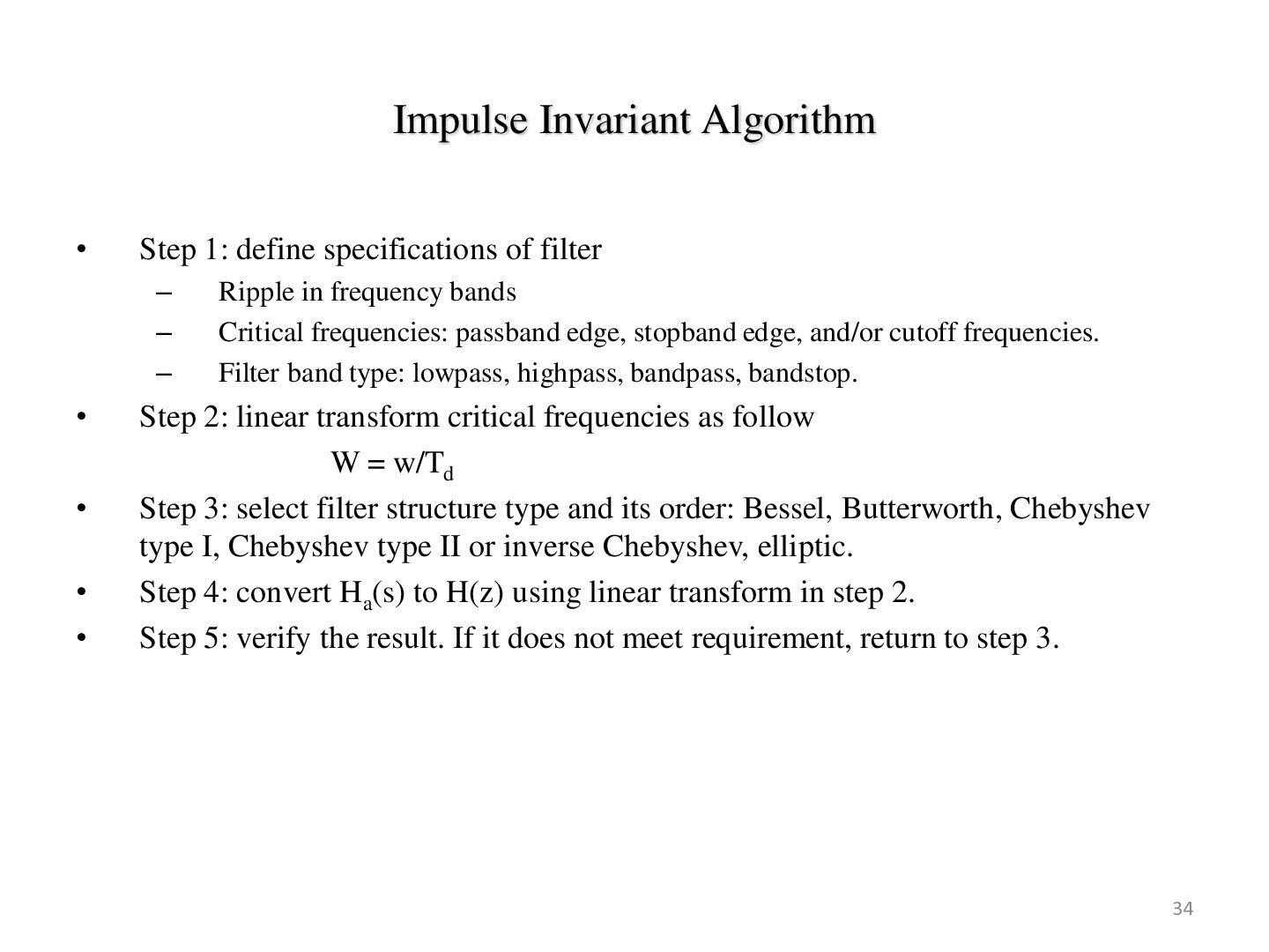
– – – • • • • Ripple in frequency bands Critical frequencies: passband edge, stopband edge, and/or cutoff frequencies. Filter band type: lowpass, highpass, bandpass, bandstop. Step 2: linear transform critical frequencies as follow W = w/Td Step 3: select filter structure type and its order: Bessel, Butterworth, Chebyshev type I, Chebyshev type II or inverse Chebyshev, elliptic. Step 4: convert Ha(s) to H(z) using linear transform in step 2. Step 5: verify the result. If it does not meet requirement, return to step 3. 34
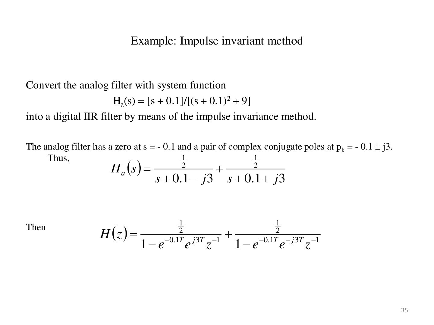
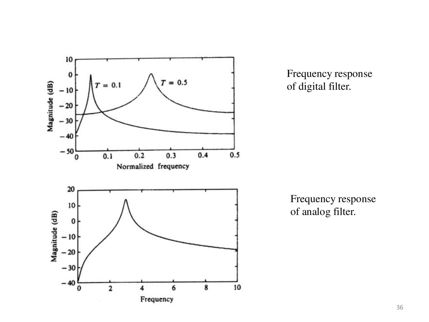
function Ha(s) = [s + 0.1]/[(s + 0.1)2 + 9] into a digital IIR filter by means of the impulse invariance method. The analog filter has a zero at s = - 0.1 and a pair of complex conjugate poles at p k = - 0.1 j3. 1 1 Thus, H a s Then H z 2 s 0.1 j 3 1 e 1 2 0.1T e j 3T z 1 2 s 0.1 j 3 1 e 1 2 0.1T j 3T e z 1 35
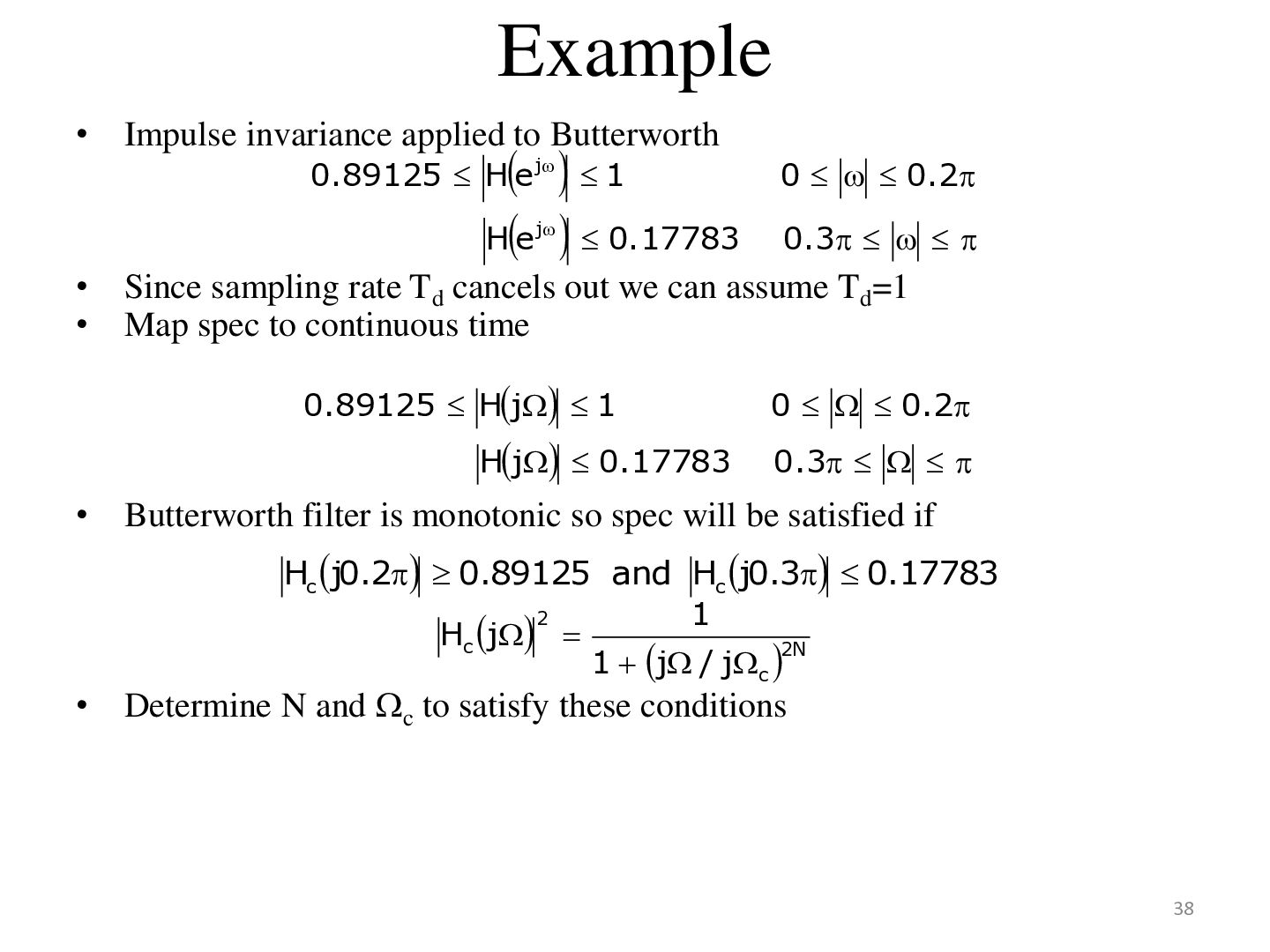
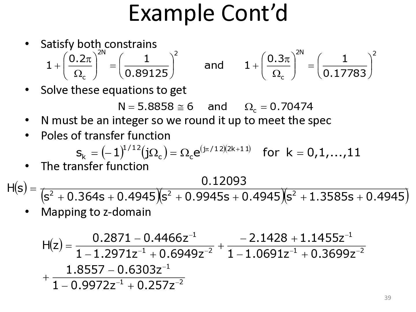
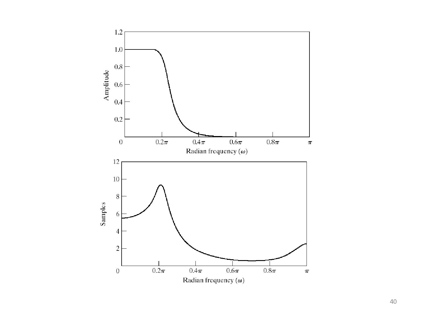
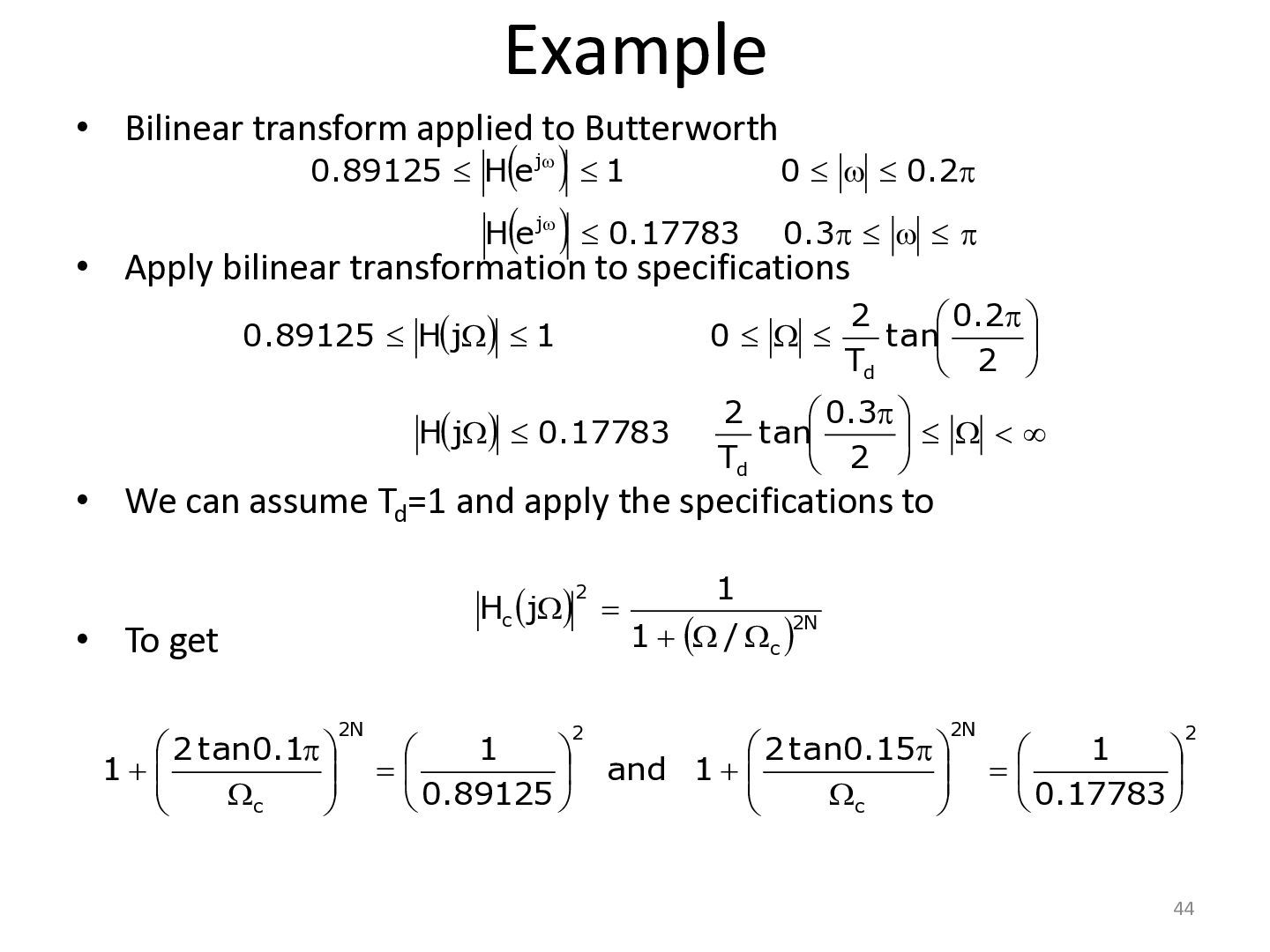
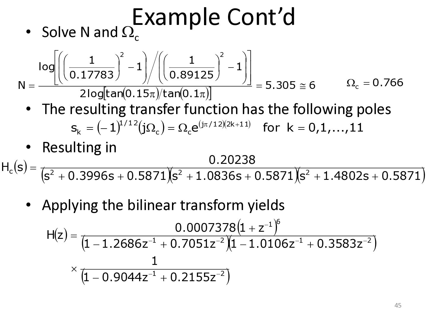
0.17783 0.89125 H e j 1 j • • Hj 0.17783 • 0.3 Since sampling rate Td cancels out we can assume Td=1 Map spec to continuous time 0.89125 Hj 1 • 0 0.2 0 0.2 0.3 Butterworth filter is monotonic so spec will be satisfied if Hc j0.2 0.89125 and Hc j0.3 0.17783 2 1 Hc j 2N 1 j / jc Determine N and c to satisfy these conditions 38
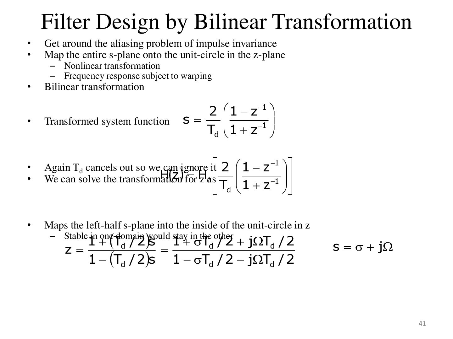
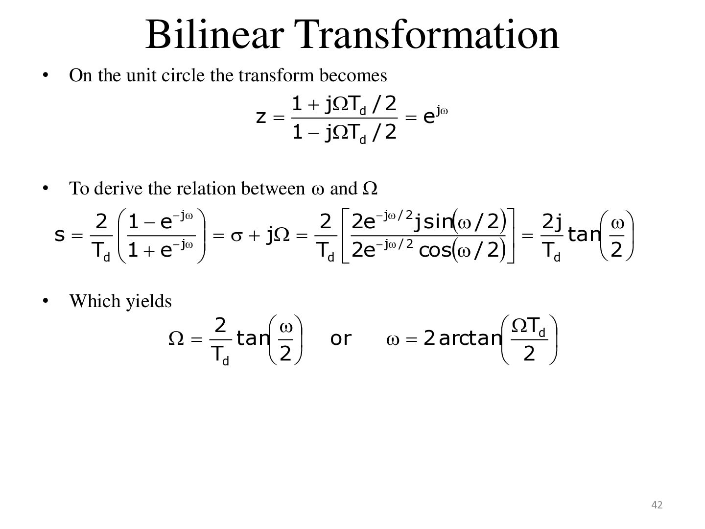
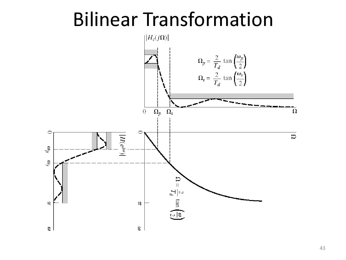
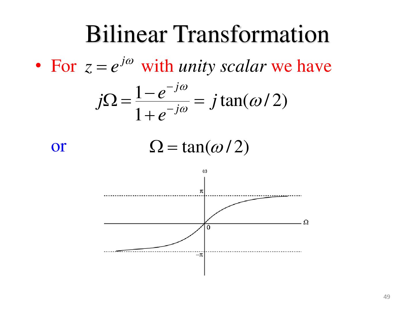
aliasing problem of impulse invariance Map the entire s-plane onto the unit-circle in the z-plane • Bilinear transformation – Nonlinear transformation – Frequency response subject to warping 2 1 z1 s 1 Td 1 z • Transformed system function • • Again Td cancels out so we can ignore it 2 1 z 1 H z for H We can solve the transformation z cas 1 • Maps the left-half s-plane into the inside of the unit-circle in z Td 1 z 1 Td / 2s 1 Td / 2 jTd / 2 1 Td / 2s 1 Td / 2 jTd / 2 – Stable in one domain would stay in the other z s j 41
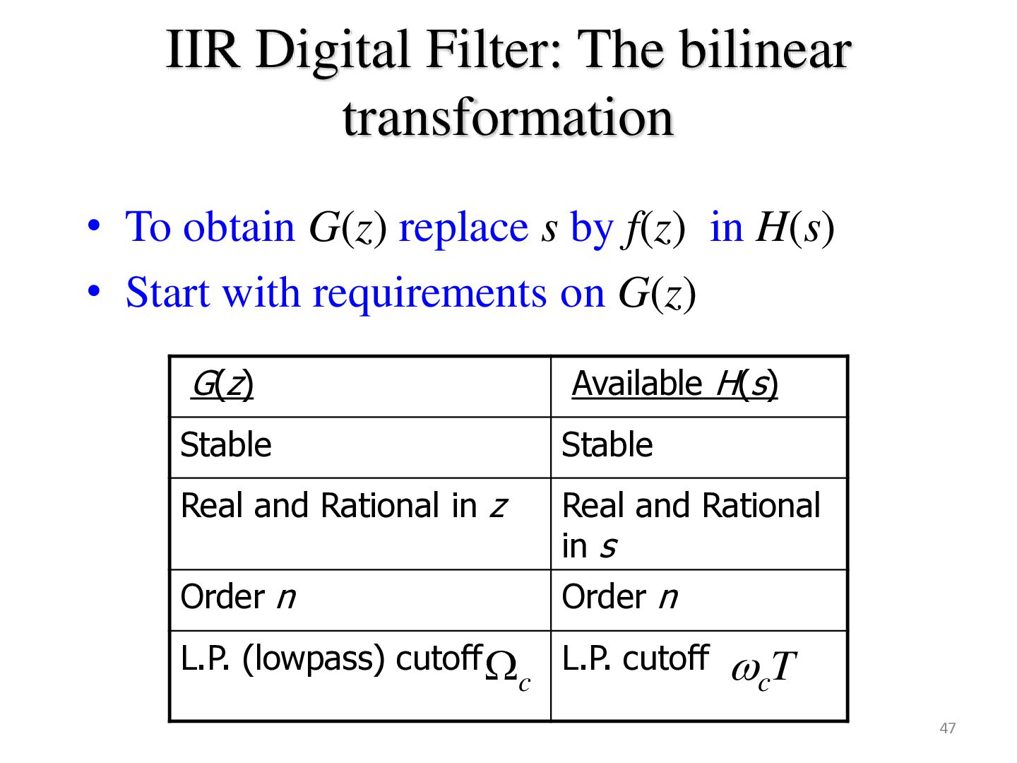
replace s by f(z) in H(s) • Start with requirements on G(z) G(z) Available H(s) Stable Stable Real and Rational in z Order n Real and Rational in s Order n L.P. (lowpass) cutoff L.P. cutoff T c c 47
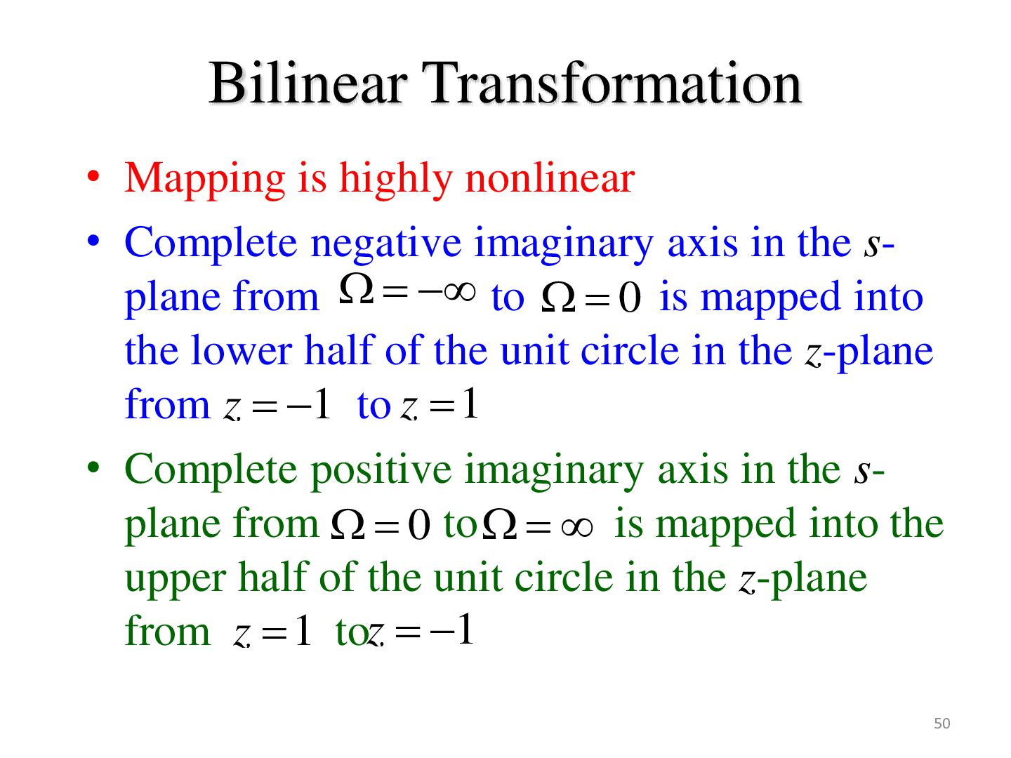
imaginary axis in the splane from to 0 is mapped into the lower half of the unit circle in the z-plane from z 1 to z 1 • Complete positive imaginary axis in the splane from 0 to is mapped into the upper half of the unit circle in the z-plane from z 1 toz 1 50
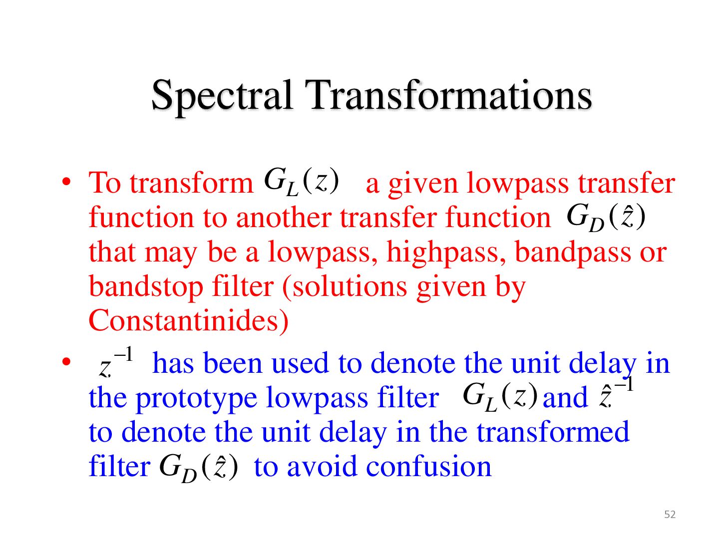
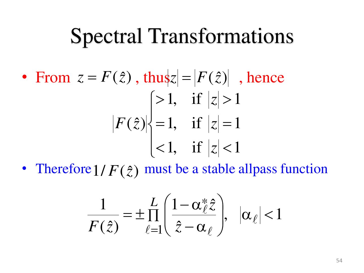
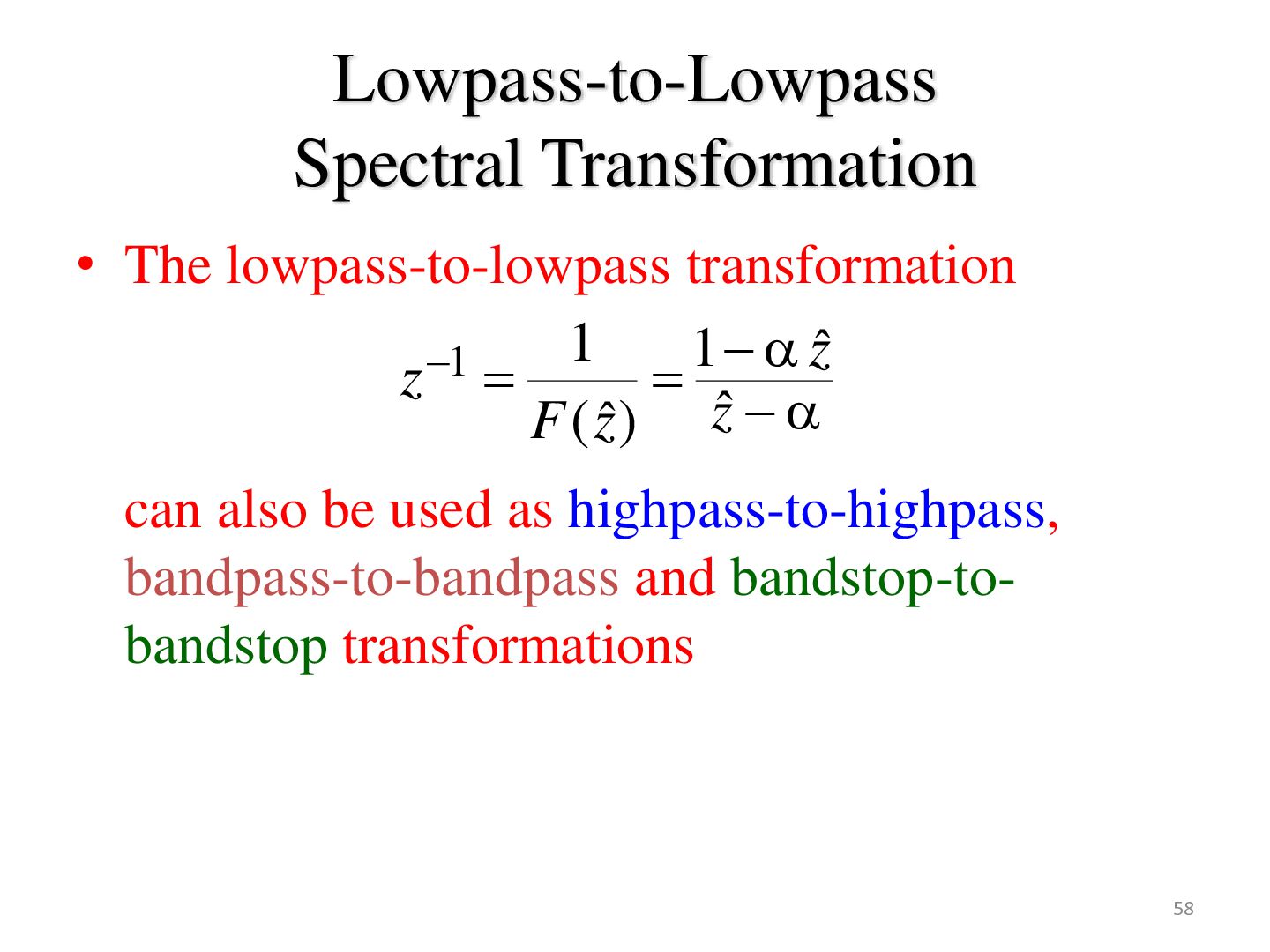
lowpass transfer function to another transfer function GD (zˆ ) that may be a lowpass, highpass, bandpass or bandstop filter (solutions given by Constantinides) • z 1 has been used to denote the unit delay in 1 the prototype lowpass filter GL (z ) and zˆ to denote the unit delay in the transformed filter GD (zˆ ) to avoid confusion 52
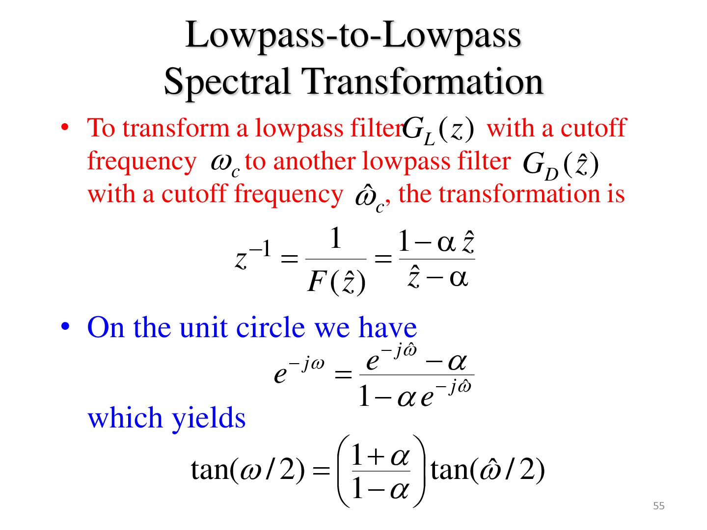
) with a cutoff frequency c to another lowpass filter GD (zˆ ) with a cutoff frequency ̂ c, the transformation is 1 1 zˆ F ( zˆ ) zˆ • On the unit circle we have jˆ j e e jˆ 1 e which yields 1 tan( / 2) tan(ˆ / 2) 1 z 1 55
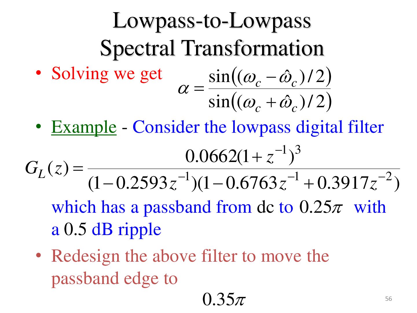
ˆ c ) / 2 sin ( c ˆ c ) / 2 • Example - Consider the lowpass digital filter 0.0662(1 z 1 )3 GL ( z ) 1 1 2 (1 0.2593 z )(1 0.6763 z 0.3917z ) which has a passband from dc to 0.25 with a 0.5 dB ripple • Redesign the above filter to move the passband edge to 0.35 56
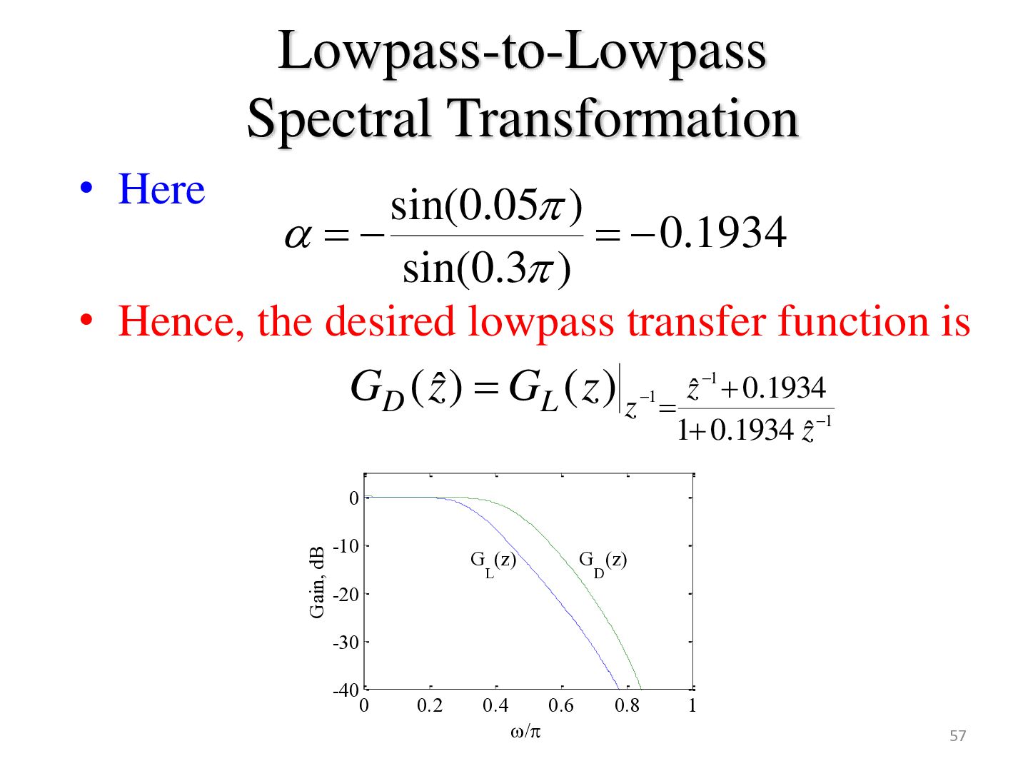
0.1934 sin(0.3 ) • Hence, the desired lowpass transfer function is GD ( zˆ ) GL ( z ) z zˆ 0.1934 1 1 1 0.1934 zˆ 1 Gain, dB 0 -10 G (z) G (z) L D -20 -30 -40 0 0.2 0.4 0.6 / 0.8 1 57
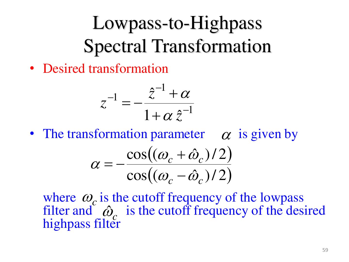
z 1 zˆ 1 1 • The transformation parameter is given by cos ( c ˆ c ) / 2 cos ( c ˆ c ) / 2 where c is the cutoff frequency of the lowpass filter and ̂c is the cutoff frequency of the desired highpass filter 59
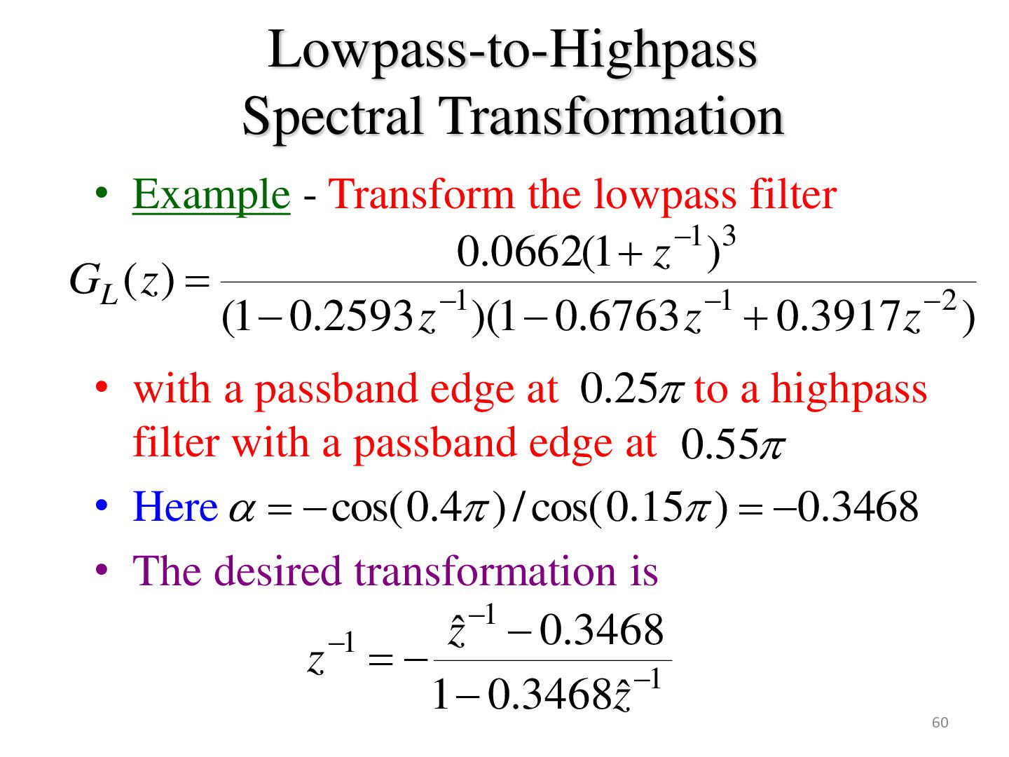
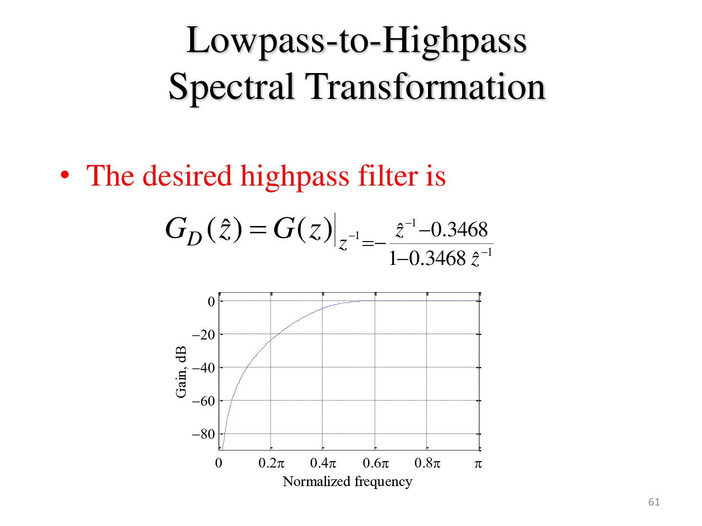
1 3 0.0662(1 z ) GL ( z ) (1 0.2593 z 1 )(1 0.6763 z 1 0.3917z 2 ) • with a passband edge at 0.25 to a highpass filter with a passband edge at 0.55 • Here cos( 0.4 ) / cos( 0.15 ) 0.3468 • The desired transformation is 1 z ˆ 0.3468 1 z 1 1 0.3468zˆ 60
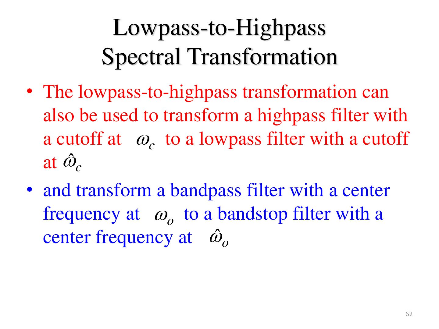
used to transform a highpass filter with a cutoff at c to a lowpass filter with a cutoff at ̂c • and transform a bandpass filter with a center frequency at o to a bandstop filter with a center frequency at ̂ o 62
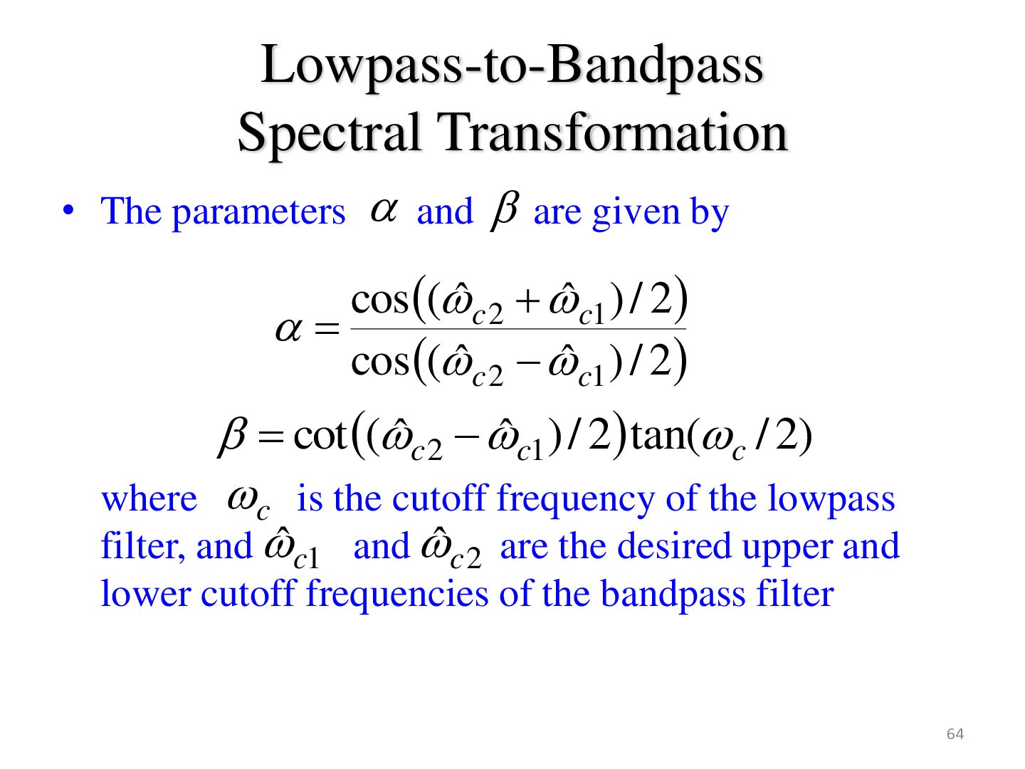
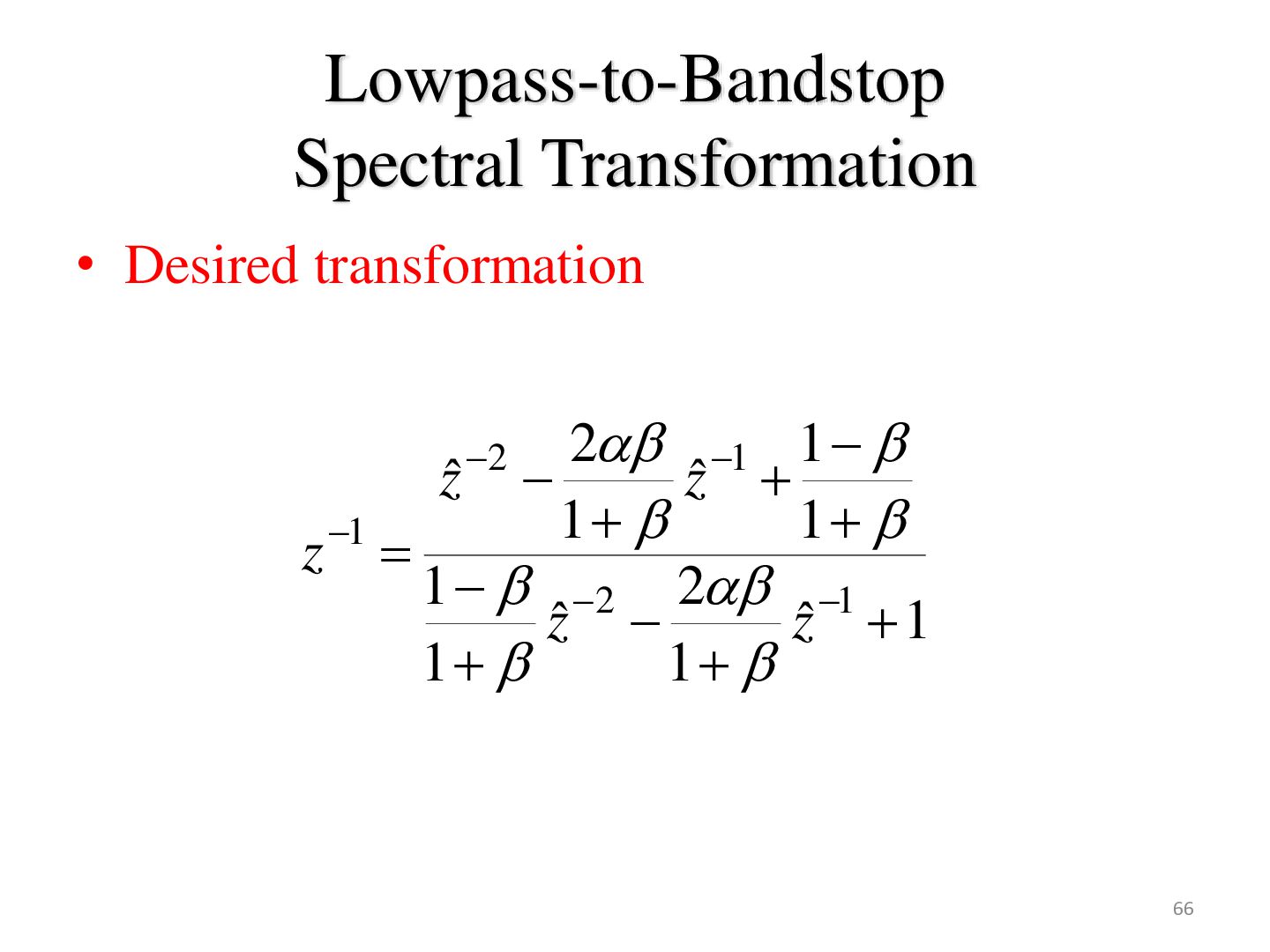
given by cos (ˆ c 2 ˆ c1 ) / 2 cos (ˆ c 2 ˆ c1 ) / 2 cot (ˆ c 2 ˆ c1 ) / 2 tan(c / 2) where c is the cutoff frequency of the lowpass filter, and ˆ c1 and ˆ c 2 are the desired upper and lower cutoff frequencies of the bandpass filter 64
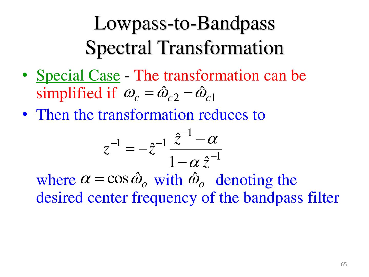
be simplified if c ˆ c 2 ˆ c1 • Then the transformation reduces to 1 z 1 1 ˆ z zˆ 1 1 zˆ where cos ˆ o with ̂ o denoting the desired center frequency of the bandpass filter 65
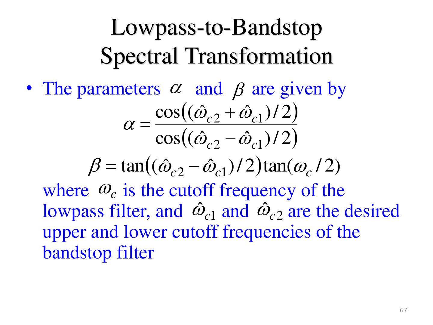
given by cos (ˆ c 2 ˆ c1 ) / 2 cos (ˆ c 2 ˆ c1 ) / 2 tan(ˆ c 2 ˆ c1 ) / 2 tan(c / 2) where c is the cutoff frequency of the lowpass filter, and ˆ c1 and ˆ c 2 are the desired upper and lower cutoff frequencies of the bandstop filter 67
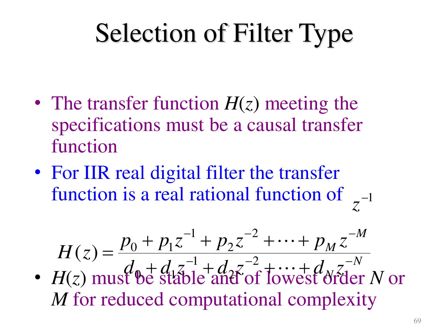
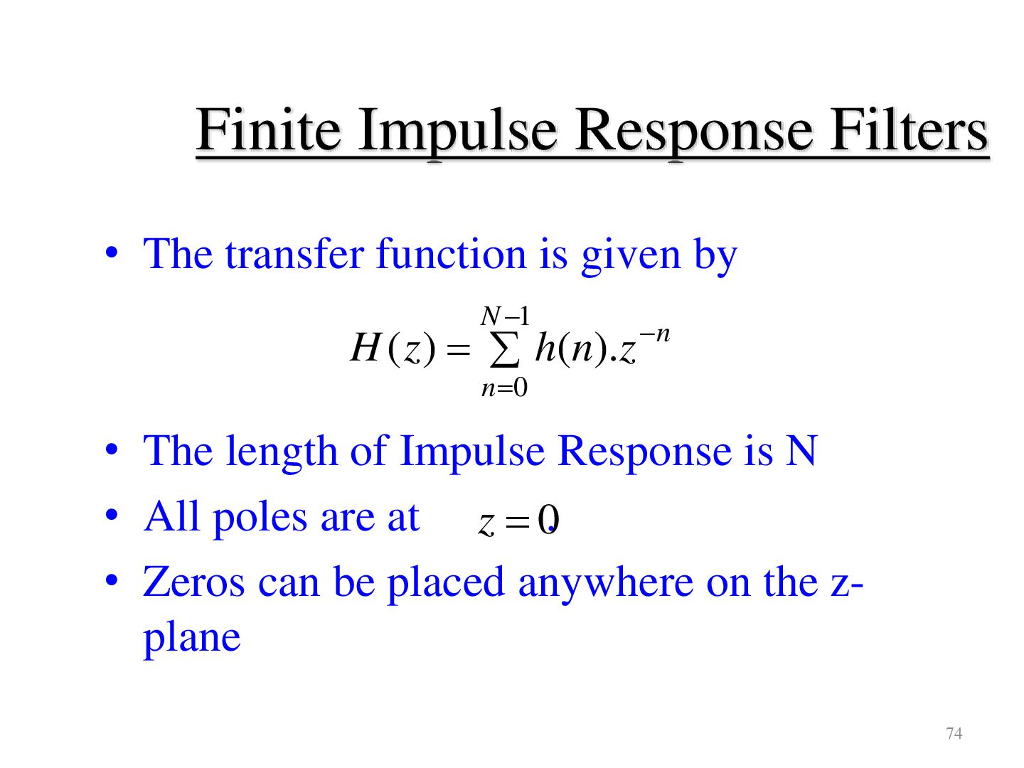
the specifications must be a causal transfer function • For IIR real digital filter the transfer function is a real rational function of z 1 p0 p1 z 1 p2 z 2 pM z M H ( z) d 0 d1 z 1 d 2 z 2 d N z N • H(z) must be stable and of lowest order N or M for reduced computational complexity 69
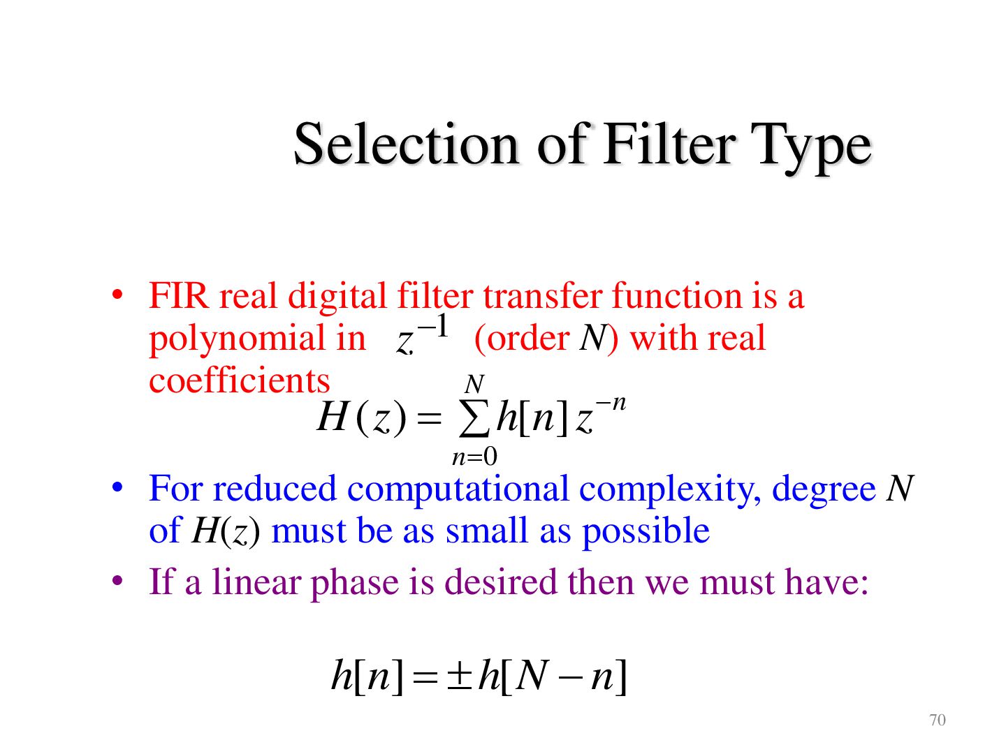
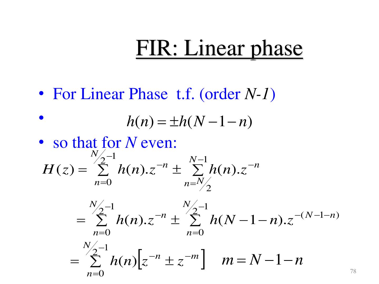
function is a polynomial in z 1 (order N) with real coefficients N n H ( z ) h[n] z n 0 • For reduced computational complexity, degree N of H(z) must be as small as possible • If a linear phase is desired then we must have: h[n] h[ N n] 70
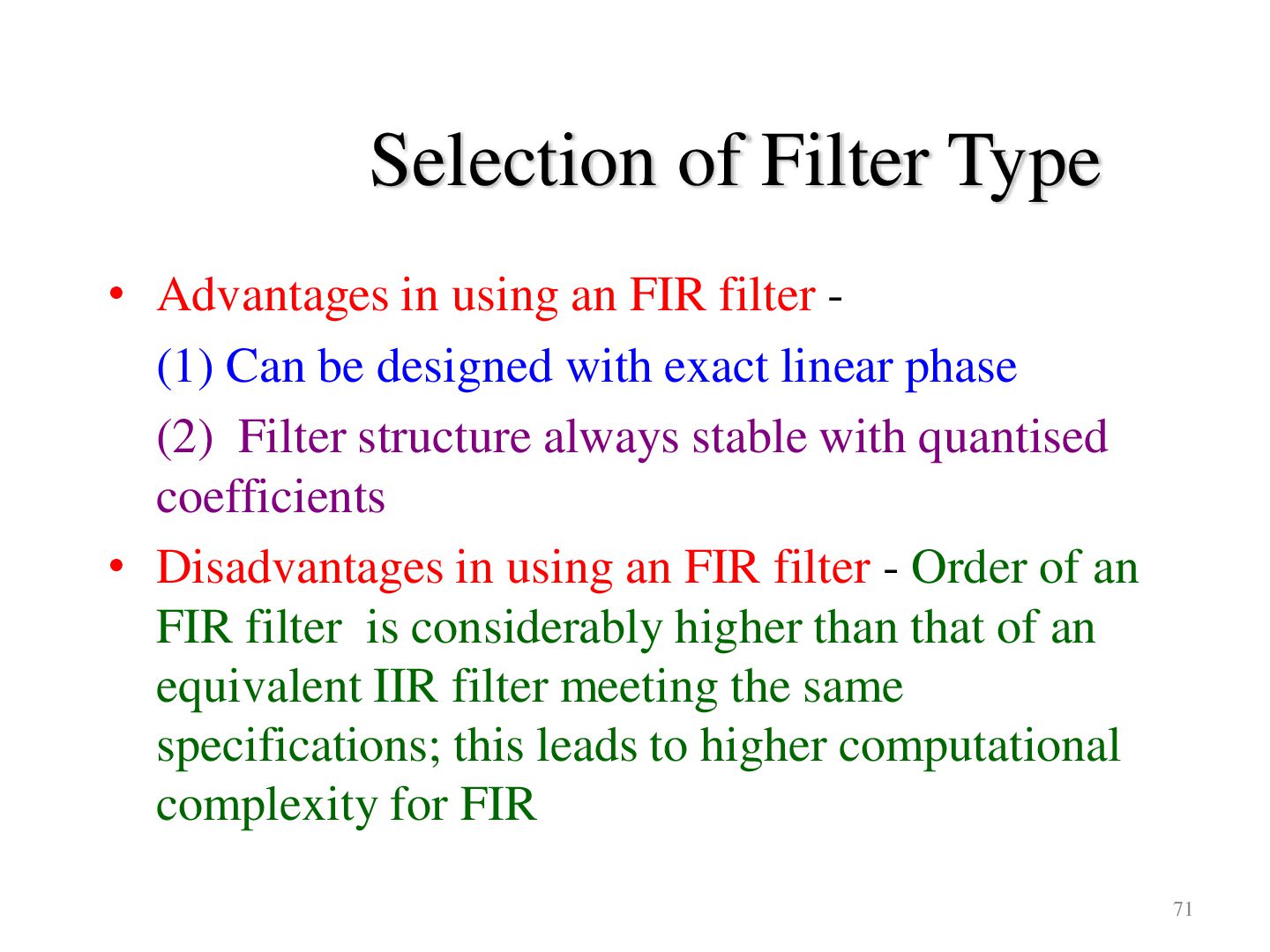
filter (1) Can be designed with exact linear phase (2) Filter structure always stable with quantised coefficients • Disadvantages in using an FIR filter - Order of an FIR filter is considerably higher than that of an equivalent IIR filter meeting the same specifications; this leads to higher computational complexity for FIR 71
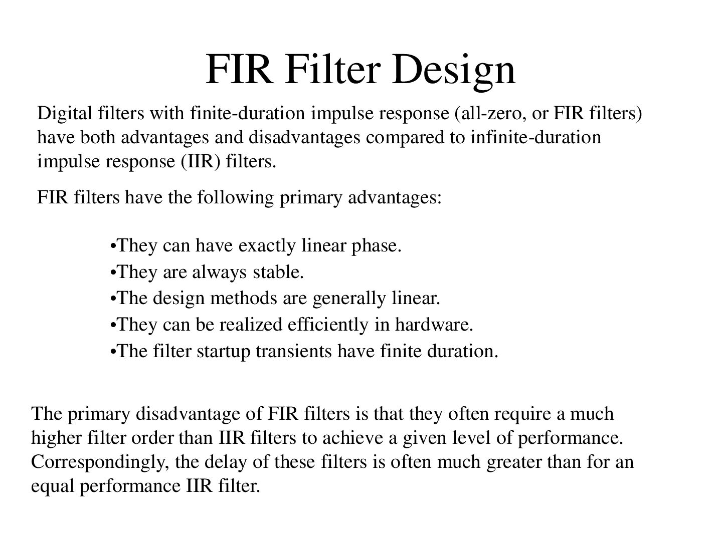
or FIR filters) have both advantages and disadvantages compared to infinite-duration impulse response (IIR) filters. FIR filters have the following primary advantages: •They can have exactly linear phase. •They are always stable. •The design methods are generally linear. •They can be realized efficiently in hardware. •The filter startup transients have finite duration. The primary disadvantage of FIR filters is that they often require a much higher filter order than IIR filters to achieve a given level of performance. Correspondingly, the delay of these filters is often much greater than for an equal performance IIR filter.
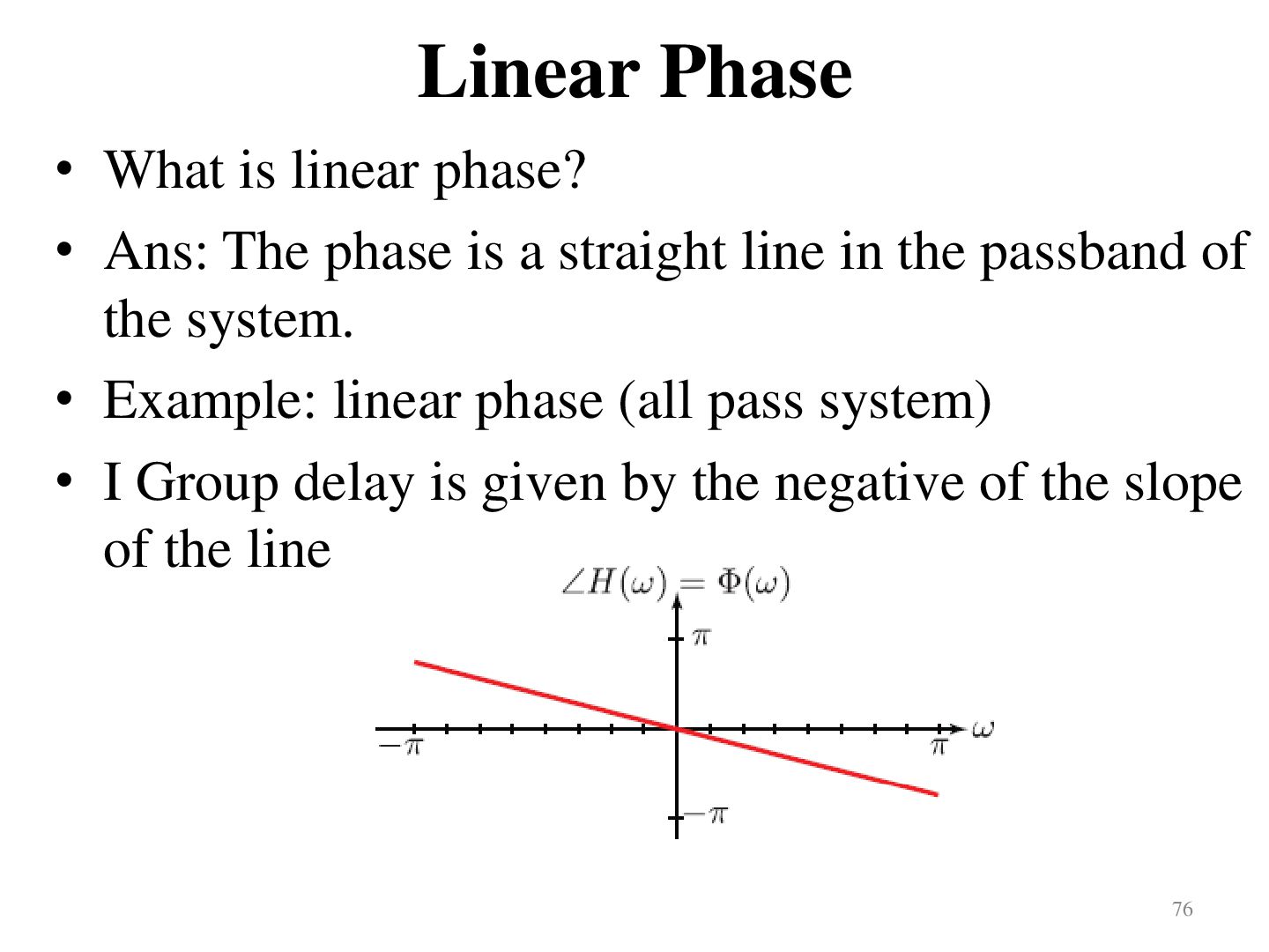
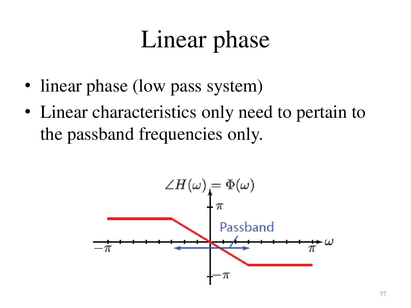
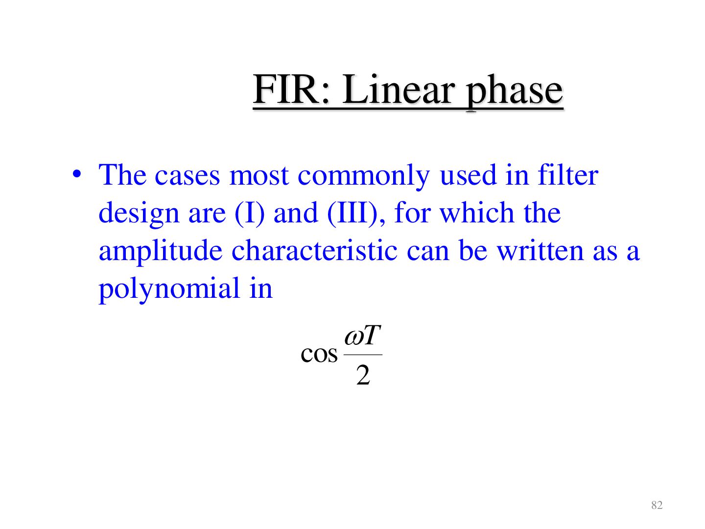
phase is a straight line in the passband of the system. • Example: linear phase (all pass system) • I Group delay is given by the negative of the slope of the line 76
• h( n) h( N 1 n) • so that for N even: N 1 2 H ( z ) h(n).z n 0 n N 1 h(n).z n n N 2 N 1 2 N 1 2 n 0 n 0 h(n).z n h( N 1 n).z ( N 1n ) N 1 2 h( n) z n z m n 0 m N 1 n 78
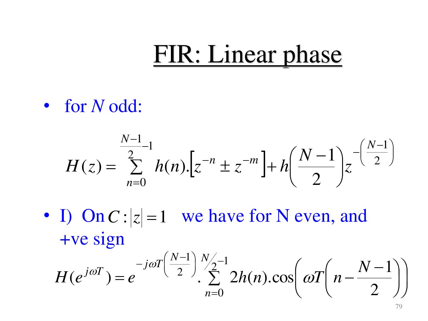
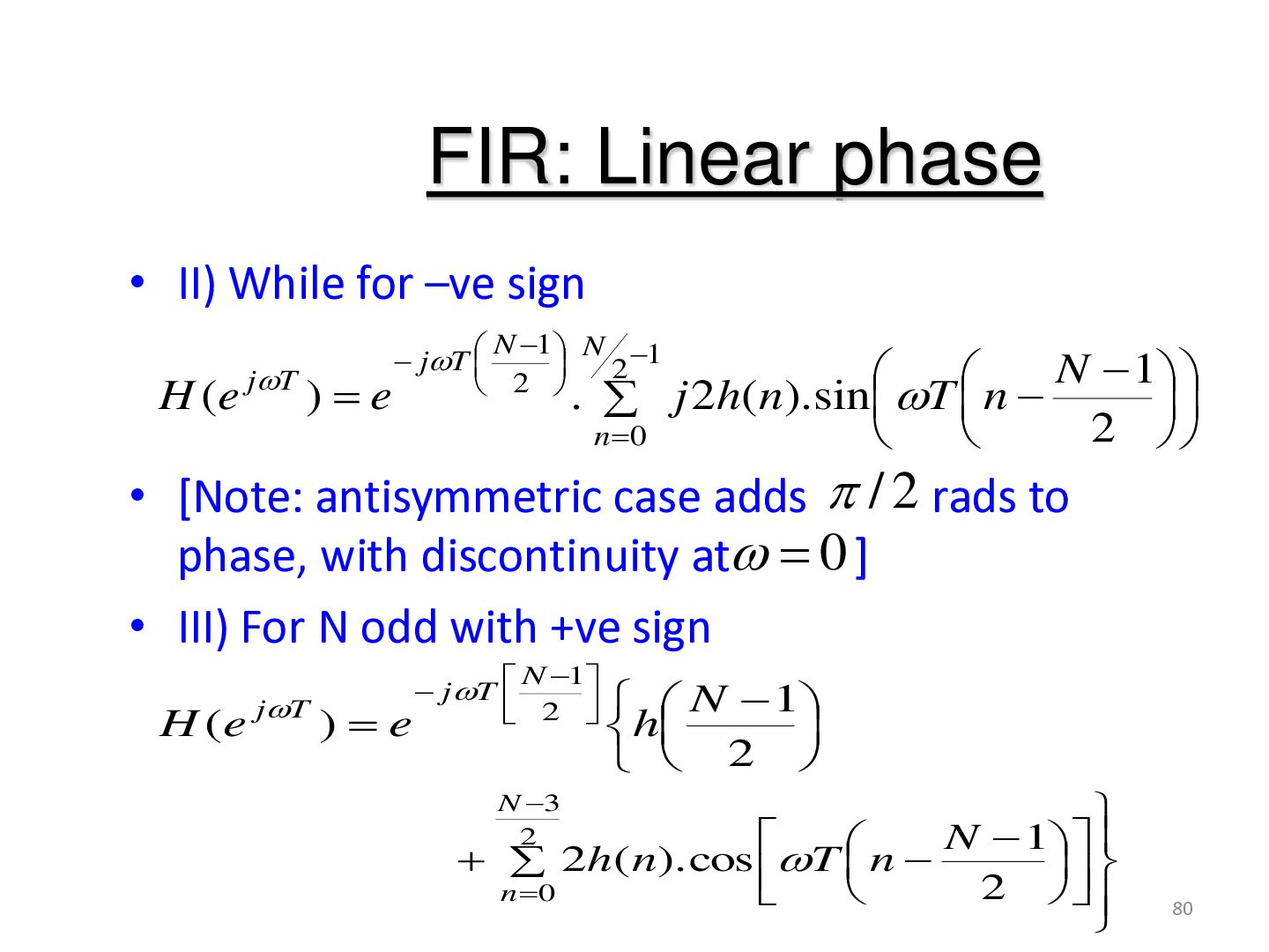
2 H ( z ) h(n). z n 0 n z m N 1 h z 2 N 1 2 • I) On C : z 1 we have for N even, and +ve sign H (e jT )e N 1 N 1 jT 2 2 N 1 . 2h(n). cos T n 2 n 0 79
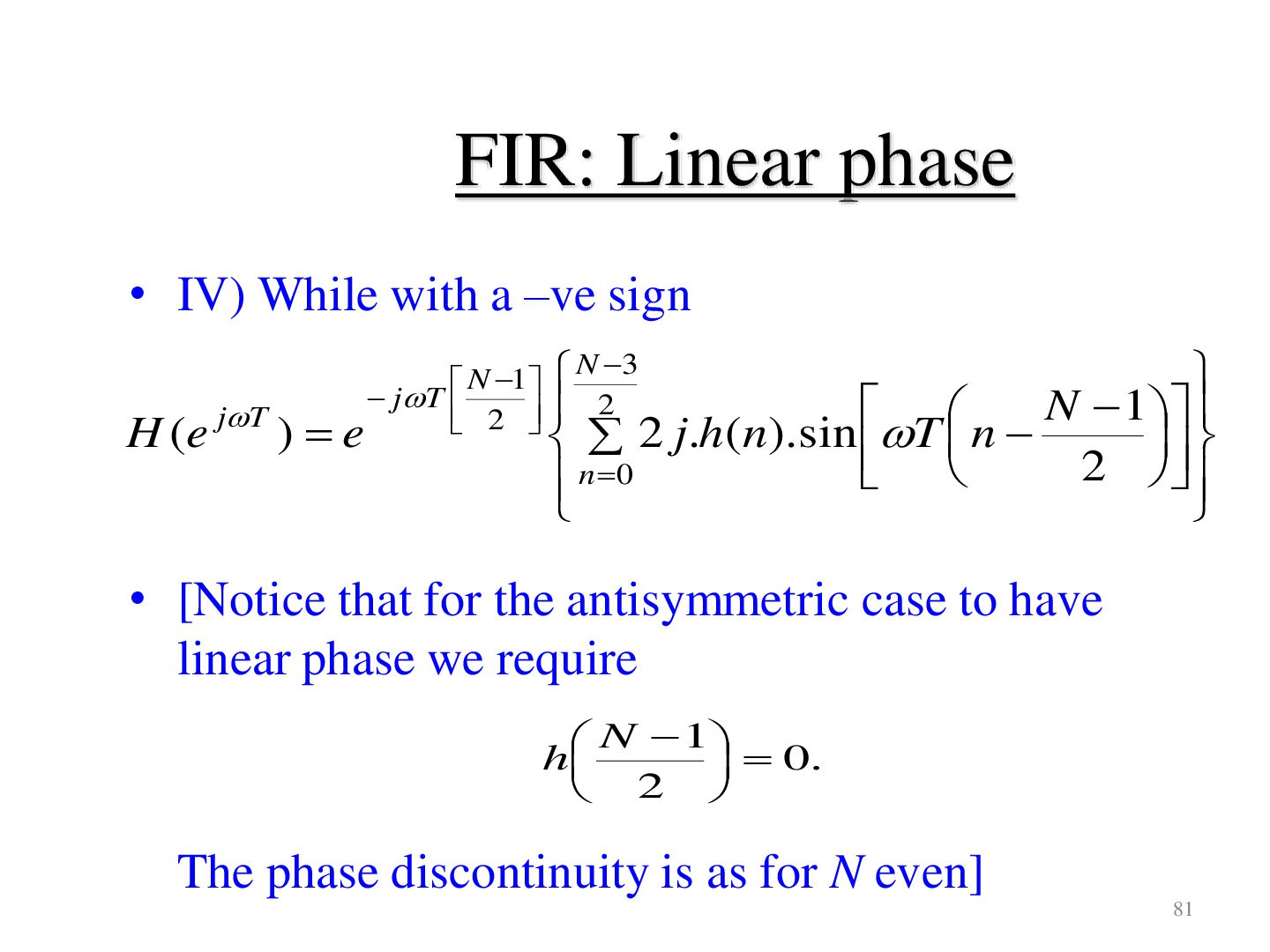
H ( e j T ) e N 1 N 3 jT 2 2 N 1 2 j.h( n).sin T n 2 n 0 • [Notice that for the antisymmetric case to have linear phase we require N 1 h 0. 2 The phase discontinuity is as for N even] 81
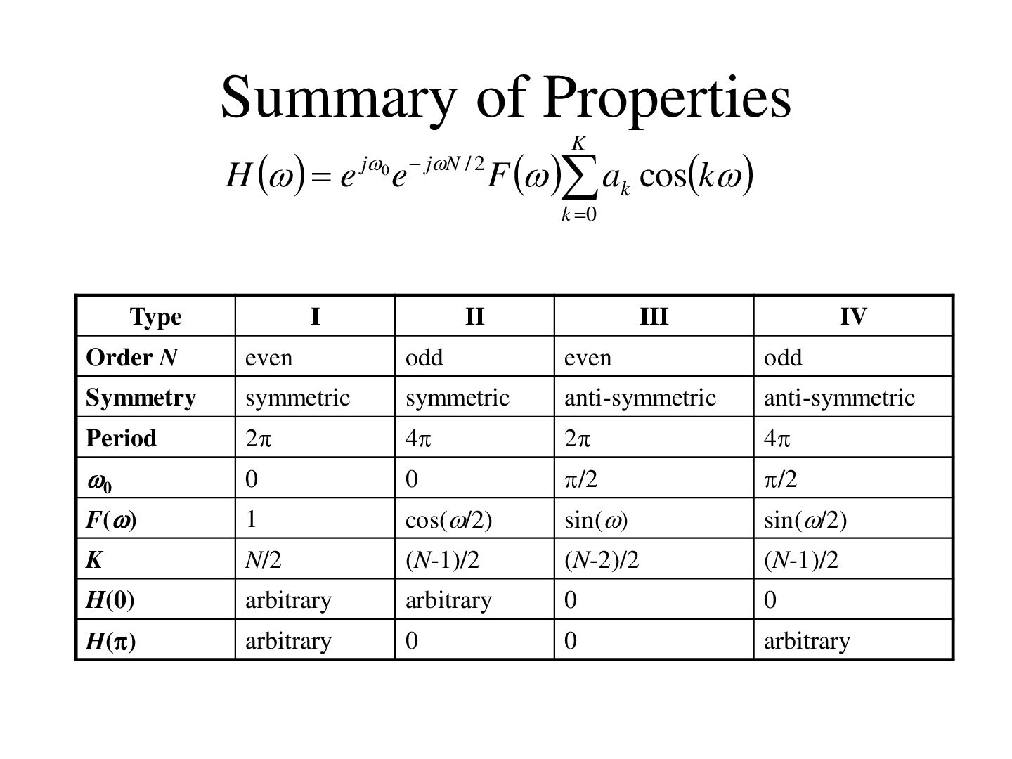
e jN / 2 F ak cosk k 0 Type I II III IV Order N even odd even odd Symmetry symmetric symmetric anti-symmetric anti-symmetric Period 2 4 2 4 0 0 0 /2 /2 F() 1 cos(/2) sin() sin(/2) K N/2 (N-1)/2 (N-2)/2 (N-1)/2 H(0) arbitrary arbitrary 0 0 H() arbitrary 0 0 arbitrary
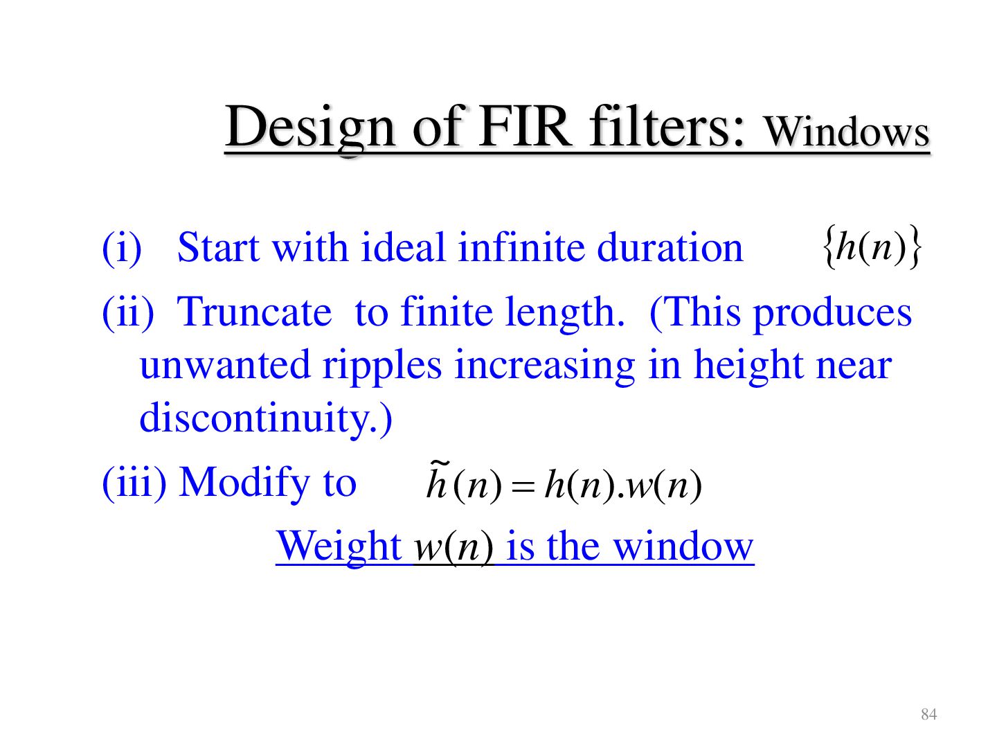
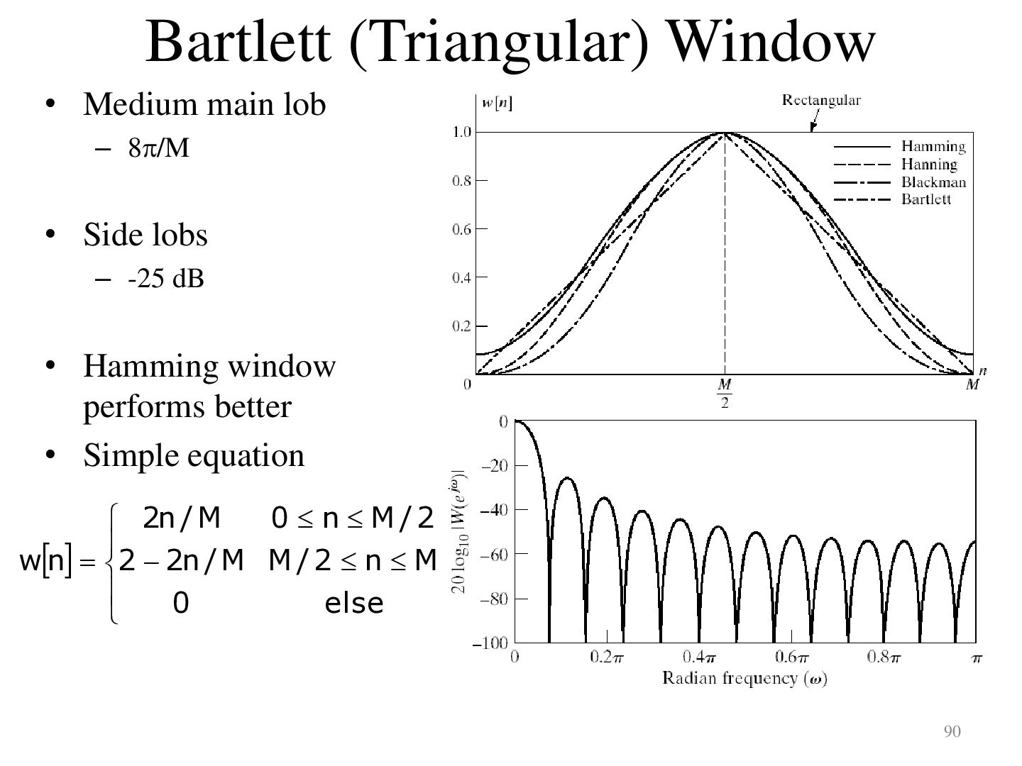
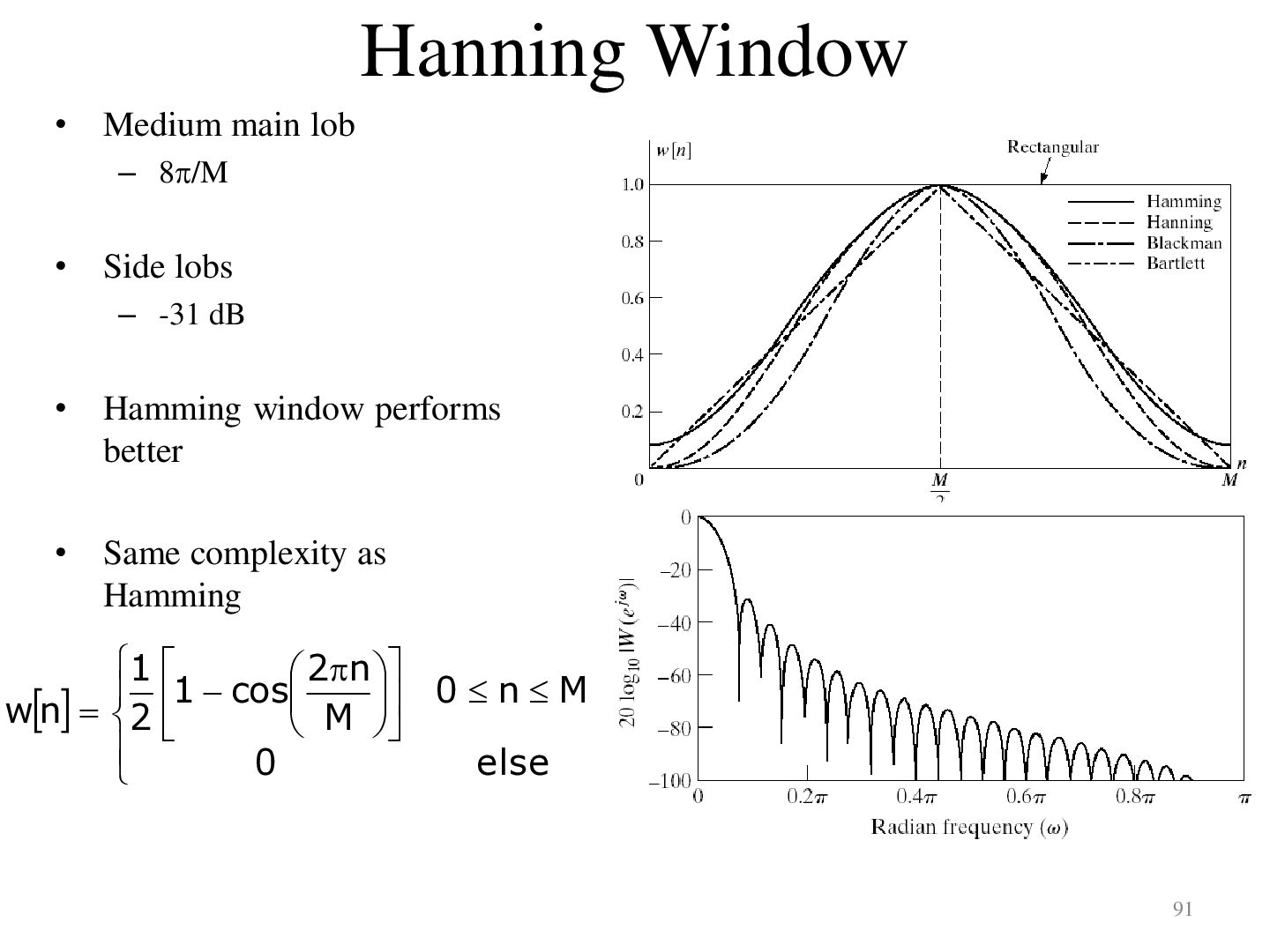
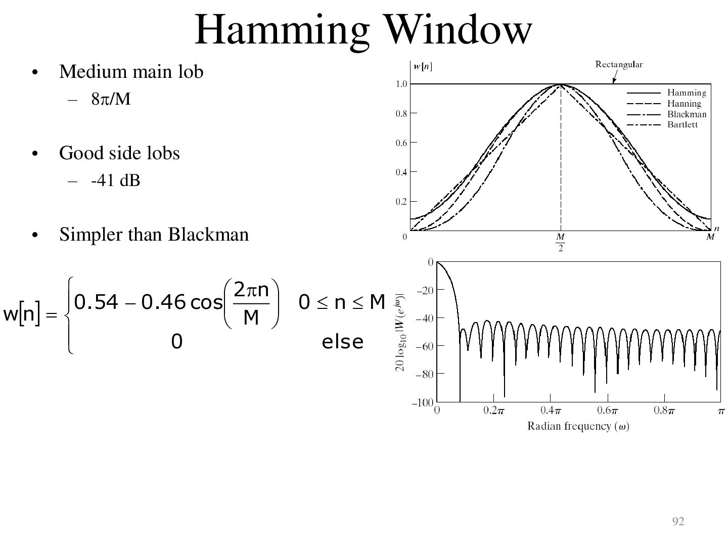
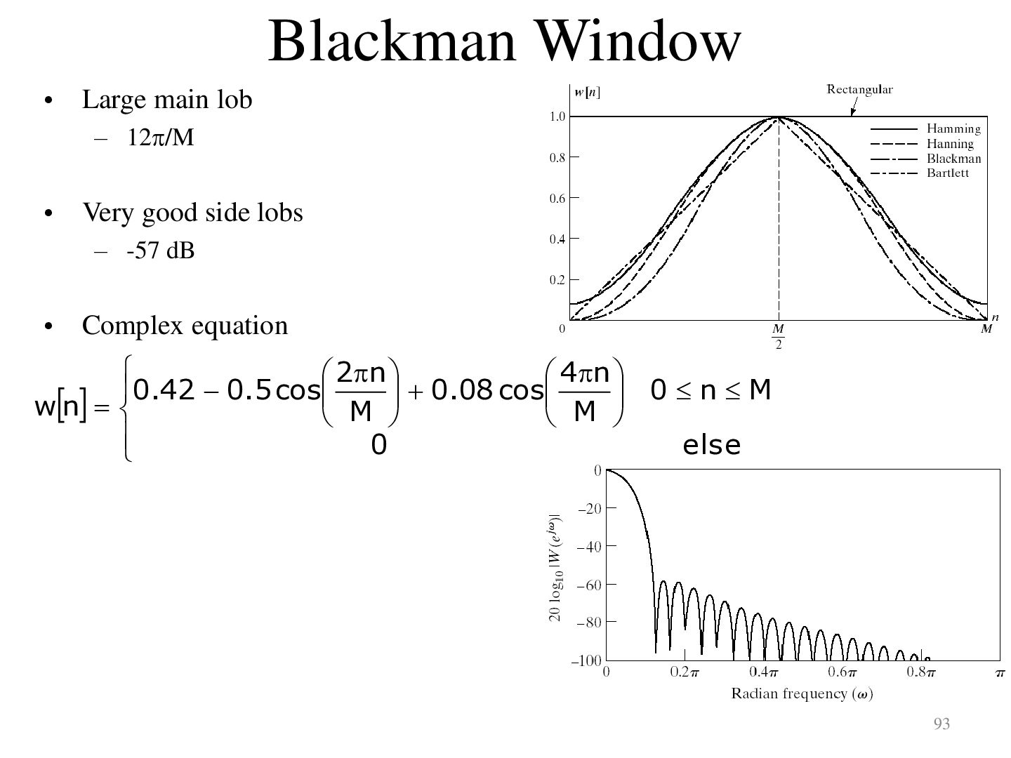
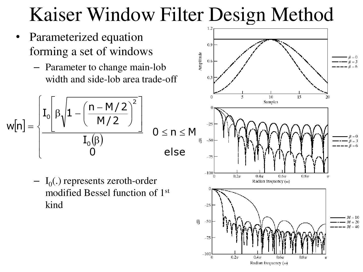
infinite duration (ii) Truncate to finite length. (This produces unwanted ripples increasing in height near discontinuity.) ~ (iii) Modify to h (n) h(n).w(n) Weight w(n) is the window 84
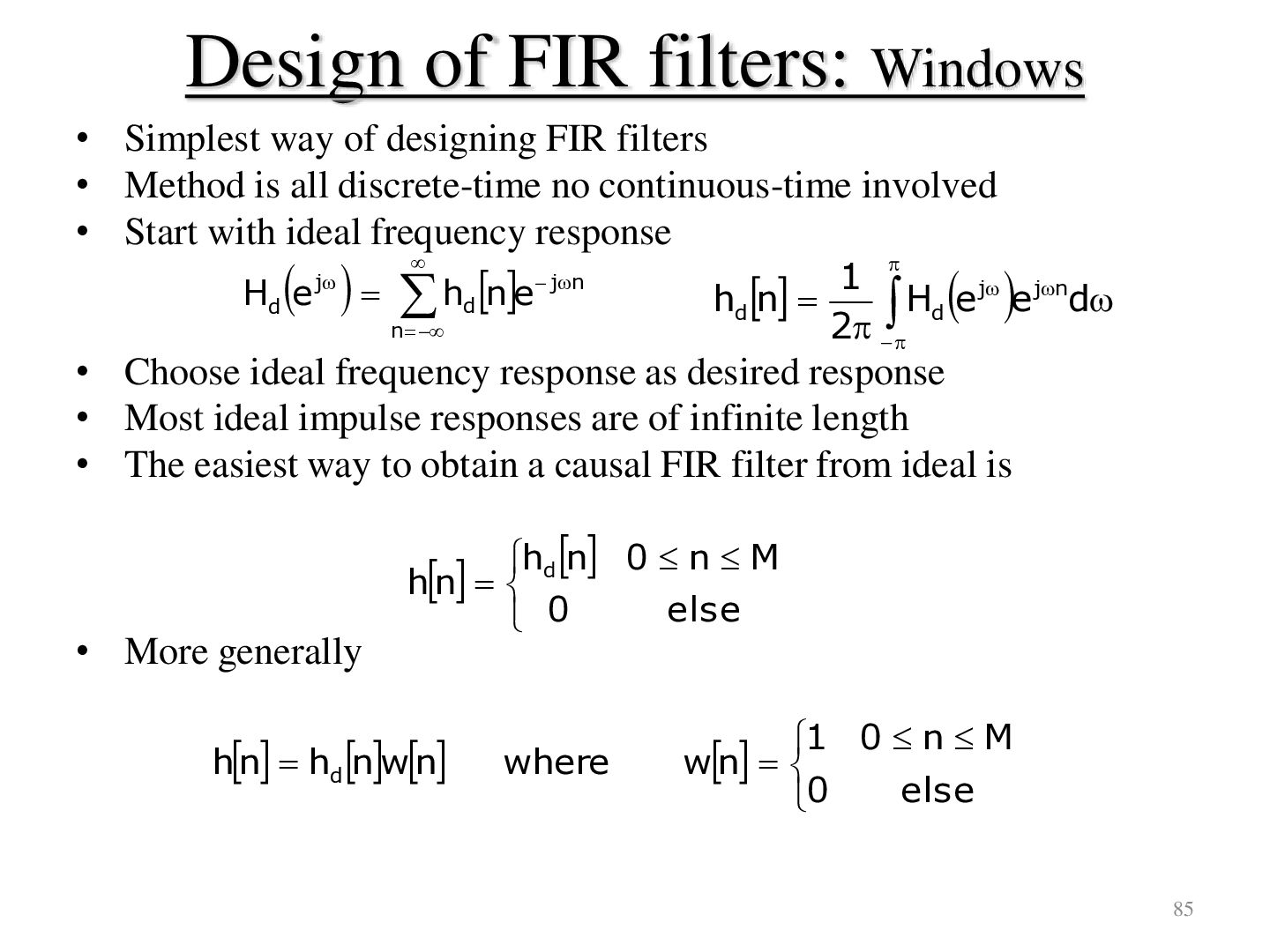
FIR filters • Method is all discrete-time no continuous-time involved • Start with ideal frequency response h ne Hd e j n d jn 1 j jn hd n H e e d d 2 • Choose ideal frequency response as desired response • Most ideal impulse responses are of infinite length • The easiest way to obtain a causal FIR filter from ideal is • More generally hd n 0 n M hn else 0 hn hd nwn where 1 0 n M wn else 0 85
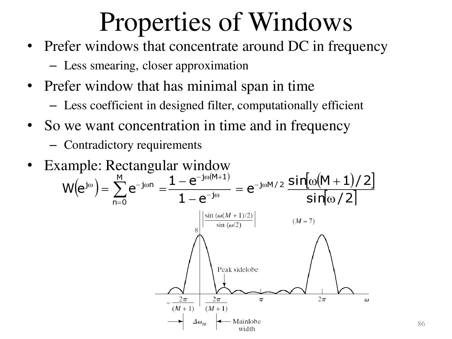
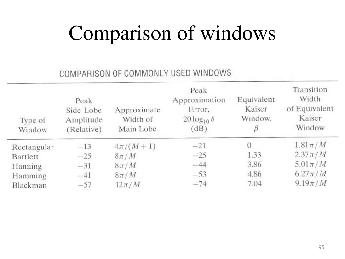
in frequency – Less smearing, closer approximation • Prefer window that has minimal span in time – Less coefficient in designed filter, computationally efficient • So we want concentration in time and in frequency – Contradictory requirements • Example: Rectangular window e We j M n0 jn 1 e jM1 jM / 2 sinM 1 / 2 e sin / 2 1 e j 86
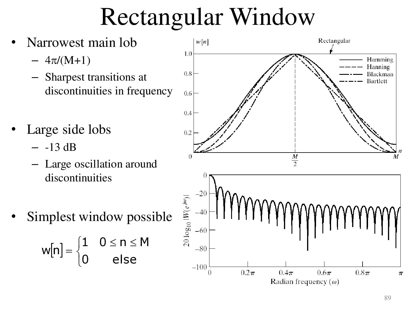
transitions at discontinuities in frequency • Large side lobs – -13 dB – Large oscillation around discontinuities • Simplest window possible 1 0 n M wn 0 else 89
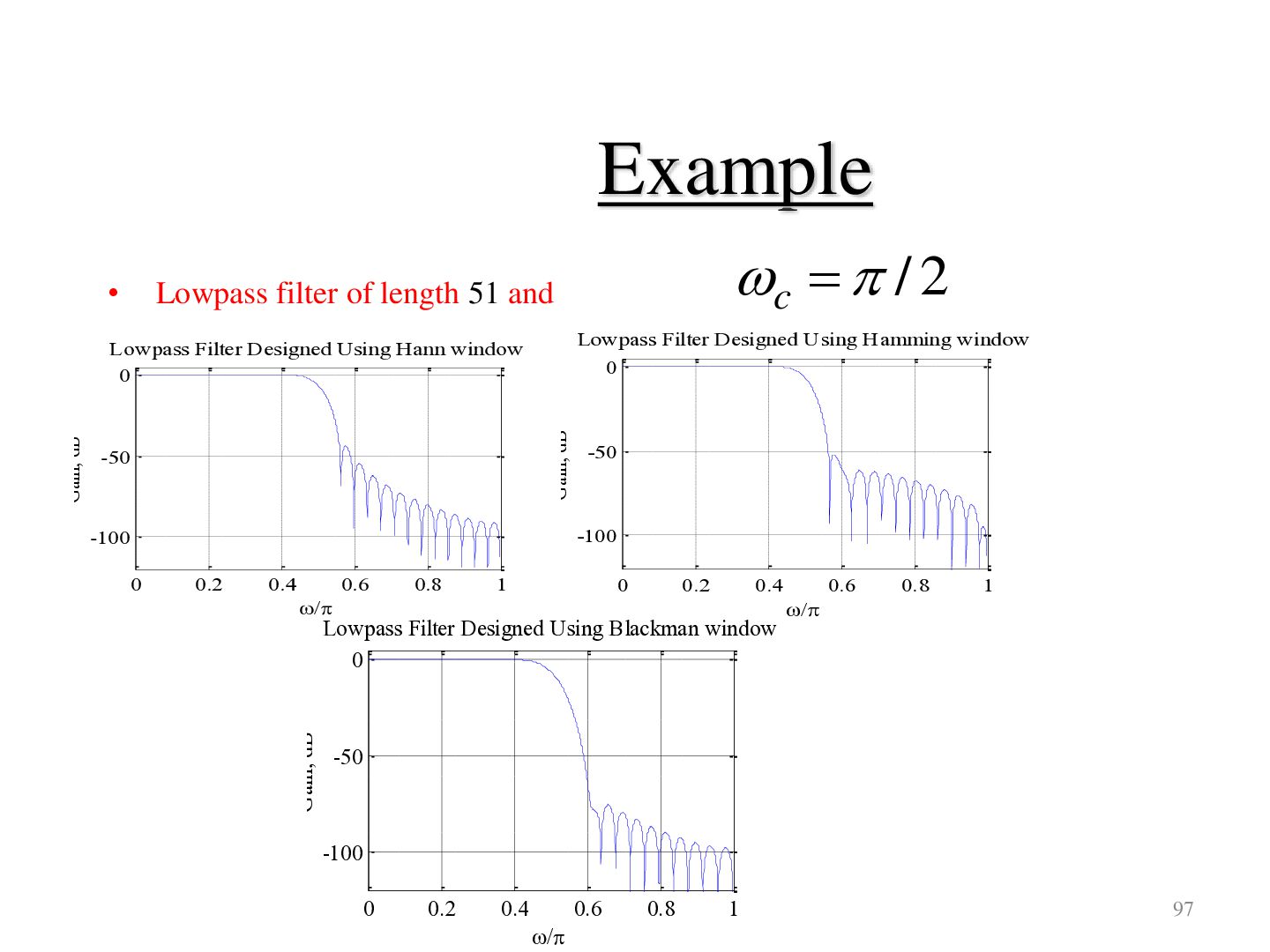
dB Lowpass Filter Designed Using Hann window 0 -50 -50 -100 -100 0 0.2 0.4 0.6 0.8 0 1 / 0.2 0.4 Lowpass Filter Designed Using Blackman window 0 Gain, dB Gain, dB c / 2 Lowpass filter of length 51 and 0.6 0.8 1 / -50 -100 0 0.2 0.4 0.6 / 0.8 1 97
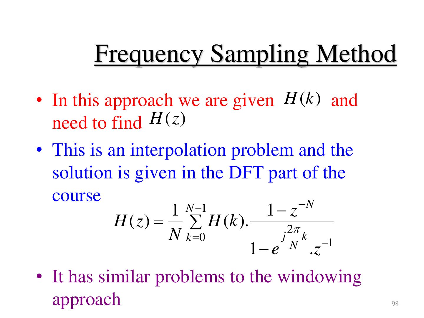
H (k ) and need to find H (z ) • This is an interpolation problem and the solution is given in the DFT part of the course N 1 N 1 1 z H ( z ) H (k ). 2 N k 0 j k 1 e N .z 1 • It has similar problems to the windowing approach 98


 poojamagdum6288
 madoxten
 katiecoart
 wayneb77
 marktimemedia
 katarinadahlin
 lara
 tomoyanonymous
 uxyall
 techseoconnect
 lauravandoore
 afnizarnur
 skipperchong