Upgrade to Pro — share decks privately, control downloads, hide ads and more …

Assessment of an aeroelastic solver for the optimization of HAWT

Christian
March 21, 2013

Assessment of an aeroelastic solver for the optimization of HAWT

In cooperation with Rotorcraft group of the Department of Mecahnical and Industrial Engineering of University Roma Tre (Prof.Massimo Gennaretti)
The final goal is the development of a numerical tool suitable for performance-optimization of Horizontal Axis Wind Turbines. It has to be a fast tool, as accurate as possible both in the aerodynamics and in structural dynamics modelling, useful to dramatically speed up the preliminary-design phase of HAWT blades layout

Christian

March 21, 2013
Tweet

More Decks by Christian

Other Decks in Research

Transcript

  1. Sviluppo di un ambiente di calcolo per la progettazione ottimizzata

    di generatori eolici ad asse orizzontale Final report Massimo Gennaretti Department of Engineering – University Roma Tre 1 Introduction This document presents the activity carried out by the Rotorcraft group of the Department of Mecahnical and Industrial Engineering of University Roma Tre (currently, Department of Engineering, UR3), under the contract ”Sviluppo di un ambiente di calcolo per la progettazione ottimizzata di generatori eolici ad asse orizzontale”(January-2012/January- 2013) financed by AirWorks (AW). The final goal is the development of a numerical tool suitable for performance-optimization of Horizontal Axis Wind Turbines. It has to be a fast tool, as accurate as possible both in the aerodynamics and in structural dynamics modelling, useful to dramatically speed up the preliminary-design phase of HAWT blades layout. The main steps of the activity are: - Development of the interface between AW’s aerodynamic code Aerodyn (Adyn), and the aeroelastic code Tiltaero, (TA), provided by UR3 (as agreed with AW). Adyn Has been improved enabling it to consider elastic deformations not only due to torsion contribution to the angle of attack, but also due to bending deflections, simultaneously allowing it to consider not axial/steady conditions. - In collaboration with AW, a database relating the main sectional aeroelastic prop- erties to a selection of meaningful internal parameters describing the actual blade section box, has been identified. - A Genetic-Algorithm, Multi-Disciplinary-Optimization (MDO) process has been set by UR3, based on the aeroelastic tool developed, to identify a configuration able to enhance the obtainable maximum power coefficients, under suitable structural constraints. 2 Short References about the Adyn and TA codes For the sake of clearness, a short description of Adyn and TA codes is here recalled. Aerodyn Adyn is a code already used by AW for the definition of the aerodynamic layout (chord, twist, and profile distribution) of Horizontal Axis Wind Turbines (HAWTs) rotor blades. 1
  2. Originally, it could only analyze axial steady flow conditions by

    a 2D aerodynamics. It is based on a given database to compute section lift, drag and moment coefficients (cL , cD , cM ) depending on the effective angle of attack. The database also includes standard corrections for great incidences which are very common on HAWT configurations. The respective section forces, circulatory lift Lc , drag D and circulatory moment Mc , are then easily obtained. Originally the effective angle of attack (1) , was given by wind velocity, rotor RPM, section pitch angle and a 3D effect due to trailed vorticity inflow. αeff (x) = tan−1( V − vi Ωx ) − θtw (x) − θ0 (1) Here x is the spanwise abscissa, θtw is the geometrical twist, θ0 is the collective pitch angle, Ω is the rotor angular velocity and V and vi are respectively the wind and the inflow velocity, normal to the rotor disc. To take into account the elastic deformation, it was mandatory to modify the effective angle of attack considered in Adyn. At first, a simple choice was made, to include only the torsion deformation, provided by the aeroelastic response by TA solutions. With respect to the previous definition in Eq. 1, it became αeff (x) = tan−1( V − vi Ωx ) − θtw (x) − θ0 − φ(x) (2) where the section torsion φ appears. Following, to better take into account the deformation contribution to the angle of attack, this has been defined as: αeff (x) = tan−1(−Up (x, t) Ut (x, t) ) (3) where Ut and Up are the components of section velocity (including inflow) in the principal axes at the aerodynamic center of the profile (see Fig. 1). They contains the informations on the full motion of the section, both rigid and elastic and they could take into account the hub motion related to nacelle and pylon movement. Also, the constraint of axial flow has, with this changes, been removed, and the considered solutions can be, now, periodic other than steady. Figure 1: Blade section velocity model Tiltaero TA is one of the aeroelastic codes developed by UR3 Rotorcraft group. It was applied in the past for several kind of aeroelastic analyses on rotary wing aircraft, both helicopters 2
  3. and tiltrotors. For an accurate description Refs. [2]-[3] are recommended.

    Basically, concerning the rotor, it is based on a beam model for the structural definition of the blades undergoing moderate deflections, and can use increasing refinements for the aerodynamics description, which, however, can be described by 2D standard models (Ref. [1]). TA’s main functionality is computing the aeroelastic response of rotorcraft undergoing straight flight, which can be generally identified by steady-periodic conditions. It can count on a very accurate kinematic modelling for every section of the blade, both related to rigid body motion, and on elastic in-plane and out-plane deflections, together with torsional rotations. The rotor can be kinematically and dynamically connected to its support, which can as well be a deformable pylon with its nacelle. The kinematics directly connects to external, inertial and aerodynamic, and internal elastic loads related to each section, which describe a set of integro-partial, differential equation for coupled biflexion-torsion deflections whose very general form is, infact: felas + finer + faerod = 0 (4) TA includes a fully-variable structural-characteristics layout, three-axis hinges, structural couplings and curved elastic axis among others. The solution of the differential equations related to each degree of freedom described (elastic bending and torsional deflections, but also angular rotations due to hinges, as well as dofs related to hub and drive-train elasticity) is obtained by following a modal approach and the known Galerkin method for spatial integration. Different analyses can be executed: • Time-Marching integration. • Harmonic Balance Response, which is a technique for the time solution of an in- herently periodic system (it is very usefull as it skips the transient solution, thus resulting very fast compared to time marching solutions). Given the nonlinear na- ture of the aeroelastic system, the solution is reached iteratively based on a standard Newton-Raphson numerical scheme. • Eigenvalue Analysis For the scope of the performance-optimization, TA’s Harmonic-Balance solution has been used, with Adyn as its aerodynamics module (see Fig. 2). 3 Performance Optimization: Background Preliminary-design is indeed a critical stage, in which conceptual mistakes can compro- mise a lot of the final success. Concerning the design af HAWT, an iterative process is usually needed to merge a performing aerodynamic layout, namely twist, chord and thickness-ratio distributions, with the technical feasibility of the blade itself, and with the structural characteristics (e.g., stiffness and mass distributions) needed to pass all the requirements for certifications, usually verified by licensed complex codes. The iterative process can be very long and time-consuming, thus only the skill and the expertise of the designer can really speed it up. The amount of time that can be necessary for preliminary design can also be a limit as for the search of innovative configurations, since the easiest and shortest way often results to be following previous experience and adapting reliable 3
  4. DATA DEFORMATION FROM PREVIOUS ITERATION Inertial section Loads Elastic section

    Loads PROCEED WITH SOLUTION REPEAT UNTIL CONVERGENCE RESULTS YES NO CONVERGENCE ? Aerodyn section Loads INDAT & INAER SECTION VELOCITY Figure 2: Simple Flow-chart of Tiltaero layouts to new blades to design, with a few room for innovation. In the attempt to satisfy the need for speed and to simplify the overall design process, the assessment of the aeroe- lastic tool for performance optimization of HAWT (POWT from now on) required the introduction and application of an optimal design procedure for the definition of HAWT blades which generated maximum power. Since it is an inherently multidisciplinary, multi- dimensional constrained maximization problem, it is very challenging and characterized by non-linear multi-modal objective functions (i.e. functions with several local maxima in the design domain). Because of this, Genetic Algorithms (GAs) seem to be one of the more appropriate approaches to solve this optimization problem. Indeed, they are able to escape local maxima and to search for a global optimum, even in very complex issues, moreover they allow the implementation of very efficient/fast computational tools, as they are intrinsically suitable for parallel programming. Performance Optimization: The Genetic Algorithm As already mentioned, in this work the blade optimization procedure is based on the application of a binary-based genetic algorithm developed by the authors [4, 5]. Genetic algorithms are probabilistic programming techniques that mimic the natural evolution in finding the optimal solution of a given problem [6]. In this process, potential solutions are called individuals and the whole set of individuals is called population. Each individual is identified by a string (chromosome) of binary digits (genes) ordered in a given sequence. The optimization procedure starts from a completely random-generated population and, at each step of the evolution process, individuals are quantitatively evaluated in terms of the corresponding value of the objective function. The population size in genetic algorithms is a crucial issue to consider when dealing with specific optimization problems, as it can seriously affect their efficiency. Indeed, a very small population (composed of few individuals) may lead to an unsatisfactory coverage of the problem domain, as well as to sampling errors [7], while a large population can lead to high computational time, due to the number of evaluations of the objective function larger than necessary. Here, following Ref. [8], an estimate of the population size based on the variance of the objective 4
  5. functions is used. Constraints are included in the optimization process

    through a quadratic extended interior penalty-function approach [9], which enhances the breeding possibility of indi- viduals potentially able to generate good offspring. In this sense, constraints are taken into account indirectly, turning the constrained optimization process into a sequence of unconstrained minimization procedures. To build a new generation, the best individuals are selected on the basis of a fitness measure evaluated from the objective function and constraints. For the present analysis a tournament selection operator is used. It is based on a random selection of four parents, which are compared one-vs-one in two pairs and the couple of ‘winners’ are selected to be parents of two children with two independent crossover operations. A single random-point crossover operator is used. Once the mate is performed, a binary uniform mutation operation is applied, to avoid premature convergence to local optima. This operator alters one or more binary digit (gene) in the chromosome by flipping it with a given probability. The amount of chro- mosome variations during the evolutionary process is controlled through a user-defined mutation probability factor, which is decreased during the optimization to reduce the im- pact of random mutations as the solution converges to an optimum. In order to prevent possible negative aspects of the evolution process and hence driving the solutions to get better over time, at each step of the optimization process the best individuals (a given, user-defined, percentage of the population size) are selected to become part of an elite group which is unchanged in the next generation. This technique, in addition to avoid- ing the possibility to obtain worse generation during the optimization process, enhances its convergence properties [10, 11]. The optimization procedure is iterated until either the chromosomes similarity (bit-string affinity) achieves a user-defined value [12], or the maximum number of iterations is reached. Performance Optimization: The Database Definition Blade’s structural characteristics are inserted into the POWT by means of an ad hoc database. It contains all the bidimensional properties of the section hosting the known aerodynamic profiles, which compose the blade. For each kind of profile the external shape is defined, while the structural features are given in a discrete manner in function of two parameters bound to the internal composition of the profile, with reference to Fig. 3 they are: Figure 3: Blade box structural sketch 5
  6. • the skin thickness ǫ. Actually it is an equivalent

    thickness. In fact, the real blade skin is composed by different plies of fiberglass with different mechanical characteristics (e.g., unidirectional, biaxial and triaxial plies). Thus, in order to characterize the section, a typical configuration as for the plies sequence was assumed and then the only thickness was given a range of variation with a fixed 1m long chord. Moreover, a second parameter influences ǫ, that is the spar thickness s in Fig. 3, which in turn increases together with the skin thickness. • The dimension of the blade-box chordwise width L. Also in this case a typical I shape was assumed. The spar has a characteristic sandwich structure, with a PVC core and a fiberglass, bidirectional-ply skin. The allowed range of variation spreads from 0% to 80% of the chord1. The needed section’s properties are: - Section mass m[kg m ] - Axial stiffness EA[N] - Shear center position w.r.t. Leading edge position (Ye , Ze )[m] - Aerodynamic center position w.r.t. Leading edge position (Ya , Za )[m] - Centroid position w.r.t. elastic center (ηc , ζc )[m] - C.G. w.r.t. elastic center (ηc , ζc )[m] - Radius of giration w.r.t. principal axes R1 and R2 [m], together with principal axis angular position αR [deg] w.r.t. chord. - Bending stiffness EIη and EIζ [Nm2], together with figure axis angular position αEI [deg] w.r.t. chord. - Torsional stiffness GJ [Nm2] Every value contained into the database is computed with respect to a unitary chord c0 . The real value must so be multiplied by ck, where k depends on the specific property, ac- cording to dimensional considerations. The database was generated using the structural modul of the commercial code FOCUS6. It is a FEM tool for the structural analysis of HAWT blades, which also provides as output the section properties. For every aerody- namic profile a unitary-chord blade has been created on which more analyses have been made for a range of ǫ and L. The analysed profiles were DELFT40, DELFT30, DELFT35, DELFT25, DELFT21 and NACA64-618. Further, two typical kind of root section were used: • a circular section, where L = 0, characterized by higher skin thickness • a transitional, quasi-circular section between the circular one at the root, and the section with maximum chord. Here, a profile was chosen with maximum thickness equal to 85 % of the chord, whose geometry is an average value between circular section and the DELFT40 profile. 1When L = 0 the only structural stiffness is given by ǫ. It is the case of the tip sections because of their small chords 6
  7. TILTAERO + AERODYN OPTIMIZER Design variables Spar width + skin

    Layer Chord,Twist, Profile position Reconstruction of Structural and Inertial properties Cp + Constraints Figure 4: Optimization Design Process Schematics Performance Optimization: The Optimal Blade-design Proce- dure As stated in the agreement with AW, the optimization process is here applied to design a HAWT-blade such that a maximum power coefficient (CP ) can be obtained. Although different objective functions could be defined (e.g., annual energy production), it was decided to start from getting the maximum CP , usually defined for θ0 = 0, that is a null collective angle condition. The power coefficient has, thus, been included in the objective function to maximize. In literature some optimization procedures can be found for the aerodynamic layout (i.e. Twist, chord and Thickness-Ratio’s distributions) of HAWTs. Differently, here it was decided to directly consider, within the procedure, some relevant structural quantities as design variables, adding them to the aerodynamic-layout characteristics. The choice of these structural elements was made by AW because of its experience related to the real internal composition of a blade-box ,e.g., covering skin, load-bering elements, determining the structural properties of a HAWT blade. Each variable (except one as it is specified in the following) is defined for every different profile that the designer places along the blade span. The first step for the design procedure, is, thus, to decide on the base of the expertise (and the availability of aerodynamic database) which profiles to use and in which order to place them from the blade root to the tip. The design variables associated to each profile are: • the profile’s span-wise positions yp . Given N profiles along the span, N − 2 yp are variable, as root and tip positions are not unknown. • ts (yp ), a relative equivalent thickness,the ratio between the blade skin-equivalent characteristics and the chord for a given position (It is the parameter ǫ according to Fig.3). • swr(yp ), a ratio between the internal-spar width (L in Fig.3), constant along the span, and the local chord. The internal-spar is a supporting structure. It is con- sidered to run almost along the all blade, unless particular reinforced section at the root are being considered. It is restrained not to exceed a fixed percentage of the corresponding chord for obvious clearance reason, and to get up to a minimum 7
  8. percentage of the blade lenght. If the maximum ratio w.r.t.

    the chord is exceeded for a certain section, no spar can be placed from that section up to the blade tip. Note that the spar width is constant along the span, so, in this case, only one design variable is defined. • θtw (yp ), the geometric twist defined for each one of the N profile considered (except if root-circular sections are defined, where the twist has no meaning). • ch(yp ) defining the chord values at the N profile’s positions. Besides design variables, some constraints have been defined. It is worth to remark that in this kind of procedures constraints, as well as the objective function are very easy to change, as they actually are some numbers with which the aeroelastic tool and the optimizer code exchange informations between them. Up to now it was decided them to be: • Blade-weight • Tip-clearance when passing by the pylon • Blade bending moment Fig. 4 partially explains how the optimizing procedure goes on for each individual ex- amined. Following the genetic algorithm described above, design variables are explored starting from random values taken between imposed boundaries (the setting of these boundaries is indeed an important issue as it determines the range of solutions exam- ined). From each set of design variables the chord and twist distributions along the whole span are derived by linear interpolation from the values at the different current profile’s position, and so do the relative layer thickness. To derive the structural properties of the blade that are necessary for the aeroelastic analysis, AW provided a set of coefficients representing any quantity by a polinomial ex- pression in function of the internal structure, namely of the relative skin-layer thickness and the spar width, which directly influence inertial and elastic features. Each quantity is then reconstructed from ts (yp ) and swr(yp ). Note that this implies the boundaries for ts (yp ) and swr(yp ) to be the extremes of the sampling range available, as outside this range the coefficients have no meaning. Once that all the structural and aerodynamic data are reconstructed, the aeroelastic code (TA+Adyn) computes the response, giving back the resulting CP , the blade total weight, the rotor-disc-normal displacement for tip clearance and the blade-root bending moment. Those are the objective function and the constraints to be evaluated by the genetic optimizer. 4 Numerical Results To test the optimization tool it was decided to work on a blade already designed by AW. The first AW’s design was obtained by an iterative time-consuming interaction, between Adyn’s aerodynamics, not considering elasticity, and the structural module of the commercial code FOCUS6. The optimization process described above, aims to directly design the blade both in aerodynamics and structural terms. Given the curves describing the power coefficient it was decided to try optimizing it at its peak, which was placed 8
  9. when working with a tip speed ratio λ = ΩR

    Vwind = 9.8 in nominal conditions, that is with null collective angle (θ = 0). The blade considered is 45.21m long from the hub to the 0 0.1 0.2 0.3 0.4 0.5 0.6 0 5 10 15 20 Non-dimensional Load Tip-speed Ratio, λ Non-dimensional Performance Coefficients θ0 =0 deg. Cp from Elast-Opt Cp from Elast-Opt/Rigid-Comp. Cp from Air-Works Original-Comp. Cp from Rigid-opt Figure 5: Power coefficient 0.45 0.455 0.46 0.465 0.47 0.475 0.48 0.485 0.49 0.495 0.5 9.6 9.8 10 10.2 10.4 Non-dimensional Load Tip-speed Ratio, λ Non-dimensional Performance Coefficients θ0 =0 deg. Cp from Elast-Opt Cp from Elast-Opt/Rigid-Comp. Cp from Air-Works Original-Comp. Cp from Rigid-opt Figure 6: Power coefficient peak close-up tip, and it’s shaped by 6 main different profiles distributed along its span, in the order: 9
  10. • A root circular section • A transitional, quasi circular

    section • DELFT40 • DELFT30 • NACA64-618 As already described, MDO processes based on genetic algorithms tend to converge to a global optimum if the number of individual considered is large enough. Here, with 60 gangs and 50 individuals per gang, a certain deviation from a global optimum was found, which means that different runs gave some similar but not equal results, among which the ’best’ configuration was chosen. In any case, however, all the constraint were largely satisfied. In the legend, Elast-Opt, elastic optization, means a design process where the aeroelas- ticity of the blade is considered, and all the constraints are included in the computing. Rig-Opt, i.e. rigid optimization, stands for a design in which the blade is considered rigid, only keeping the constraint on the root bending moment. Elast-Opt/Rigid-Comp, instead, means that after an aeroelastic design process, the final computation of the performances is done on a rigid blade. Fig.5 shows the power coefficients at nominal condition, evalu- ated for a large range of λ values. Coloured in red and blue one can see respectively the optimized blade (Elast-Opt) and the original AW’s blade. First it is to evidence that an increment in the peak power was obtained, as shown by the close-up image in Fig.6. This is particularly meaningful for a validation of the tool, because it shows that a good result can be obtained, getting even better performance than the real-designed blade and, most important, with a dramatically decreased computational time (less than 40 minutes on a standard QUAD-CORE architecture). Further major increments are then spread towards higher λ (up to more than 6%), that is lower wind velocity conditions. The violet curve represents the rigid-optimization design. With no elasticity involved, only the aerody- namic layout design variables (i.e. twist and chord) were defined. It is still performing and tends to the AW’s original curve, nonetheless it is less effective then the full-elastic design. The green curve at last, shows the possible mistake that can be done using the blade designed considering elasticity, and then using it with a solver not computing the elastic deformation. Especially at low wind velocity values, fairly overestimated CP are obtained. Generally speaking it appears that the effect of elasticity is confined mainly at lower speed ( highest λ), as the left part of all the computed curves is very similar for all of them. Figs.7-8 show the obtained twist and chord distributions respectively when elastic and rigid optimization are performed. With reference to the former, the original obtained twist was the one represented by blue dots. The ’zero’ value at the root (that is circular section) is imposed and has no meaning. In order to have a smoother curve trend, which results in a better technical feasibility of the blade, it was changed in the red curve, which gave non-noticeable differencies as the major changes in twist concern the very inner part of the blade which is almost ineffective. The latter figure is instead related to rigid optimization and directly compared to AW’s original blade, resulting more similar to it. Next, we examine the effect of the kind of coupling between blade section kine- matics and Adyn’s aerodynamic loads, on the blade Optimal design procedure. In fact, modifications were made to the original approach to couple Adyn aerodynamic loads to elastic deformations. At first, the idea was to use only elastic torsion to correct sectional 10
  11. -2 0 2 4 6 8 10 12 14 16

    18 20 0 5 10 15 20 25 30 35 40 45 50 Chord[m]--Twist[deg] Spanwise dimensional Position Twist and Chord Distributions Elas-Opt Twist-Revised Elas-Opt Chord Elas-Opt Twist-Original Figure 7: Twist and Chord distributions from elastic design -2 0 2 4 6 8 10 12 14 16 18 20 0 5 10 15 20 25 30 35 40 45 50 Chord[m]--Twist[deg] Spanwise dimensional Position Twist and Chord Distributions AW Original Chord AW Original Twist Rigid-Opt Chord Rigid-Opt Twist Figure 8: Twist and Chord distributions from rigid design 11
  12. 0 0.1 0.2 0.3 0.4 0.5 0.6 0 2 4

    6 8 10 12 14 16 18 Non-dimensional Load Tip-speed Ratio, λ Non-dimensional Performance Coefficients θ0 =0 deg. Cp full-deformation section velocity Cp from torsion-deformation section velocity Cp from Air-Works Original-Comp. Figure 9: Power Coefficients with different aeroelastic coupling -2 0 2 4 6 8 10 12 14 16 18 20 0 5 10 15 20 25 30 35 40 45 50 Chord[m]--Twist[deg] Spanwise dimensional Position Twist and Chord Distributions Full-deformation section velocity Twist Full-deformation section velocity Chord Torsion-deformation section velocity Twist Torsion-deformation section velocity Chord Figure 10: Twist and Chord distributions with different aeroelastic coupling 12
  13. 0 0.1 0.2 0.3 0.4 0.5 0.6 0 2 4

    6 8 10 12 14 16 18 Non-dimensional Load Tip-speed Ratio, λ Cp θ0 =0 deg. Full-deformation section velocity Torsion-deformation section velocity tors-def opt.-Full-def com. Full-def opt.-tors-def com. Figure 11: Power Coefficients with different aeroelastic coupling angles of attack, see Eq. 2, but then it was enhanced, by obtaining the incidence directly by the section velocity, which include the full elastic deformation, together with the rigid body motion, Eq. 3. The differences between the two approaches were investigated and the results are shown in Figs. 9-10. As the twist distributions are particularly different at the central part of the blade and despite the peak condition is optimized in both cases, the power curve for the older only torsion approach is sharper, and then less performing over all the λ range. Finally, a survey on the robustness of the optimized design has been made by cross check- ing the performance both of only-torsion and full-deformation contributions to section angles of attack. Indeed, the results in Fig.11 are obtained by computing the CP for the blade designed with the full-deformation-angle-of-attack section velocity, with the simpler only-torsion-angle of attack model, and viceversa. As it can be seen both the model are robust as no essential change appears. Noise analysis Starting from the aerodynamic loads evaluated for the determination of the rotor perfor- mance, the emitted noise has been determined for both the AW original blade and the optimized one. As indicated in the technical annex to the contract, this analysis is in- tended as a verification of the aeroacoustic perfomance of the blade designed through the optimization process. In particular, the investigation concerns the tonal noise as predicted by integration of the Ffawc-Williams and Hawkings equation. First, an observer located on the rotor disc at a distance of one rotor diameter from the hub has been considered (it might represent an observer on the ground). Figure 12 shows the Sound Pressure Level (SPL) of the noise perceived by such an observer, defined 13
  14. 0 10 20 30 40 50 60 70 0 1

    2 3 4 5 6 SPL dB BPF Acoustic Spectrum Optimized Blade AW original Blade Figure 12: Sound Pressure Level evaluated at an observer on the rotor disc, 2R distant from the hub. 30 35 40 45 50 55 60 65 70 90 180 270 360 450 OASPL [dB] Distance from Nacelle [m] Optimized Blade AW original Blade Figure 13: Overall Sound Pressure Level evaluated at observers on the rotor disc, placed at different distances from the hub. 14
  15. as SPLk = 20 log pk pref (5) where pk

    = (pk cos )2 + (pk sin )2 (6) and pref = 2 × 10⁻⁵Pa (7) with SPLk denoting the SPL at the k−th multiple frequency of the Blade Passing Fre- quency (BPF=3Ω for a three-bladed rotor spinnig with Ω angular velocity). The compar- ison between the noise emitted by the optimized blade and the original one revels that the former, although generating a very similar acoustic disturbance, is less annoying then the latter. Note that no acosutic constraints were included in the design process and hence this is a favourable by-product of it. Next, the noise emitted has been evaluated at different distances on the rotor disc, expressing it in terms of the overall sound pressure level (OASPL), which is defined as OSPL = 10 log P2 rms p2 ref (8) with P2 rms = k p2 k (9) Figure 13 which shows that the OASPL quickly decreases with the distance for short distances, while it becomes slower for longer distances and, similarly to what observed in Fig. 12, demonstrates that the otpimized blade is quieter than the AW original one. References [1] Hodges, D.H., Ormiston, R.A., “Stability of Elastic Bending and Torsion of Uniform Cantilever Rotor Blades in Hover with Variable Structural Coupling,” NASA TN D- 8192, April 1976. [2] Hodges D.H., Dowell E., “Nonlinear equation of motion for the elastic bending and torsion of twisted non uniform rotor blades,” December 1974 , NASA Technical Report D7818 [3] Molica Colella M. (2010), “Risposta e Stabilita’ di Velivoli Tiltrotor,” PhD Thesis (in italian) , University Roma Tre, Rome, Italy [4] G. Bernardini, C. Testa, M. Gennaretti, Optimal Design of Tonal Noise Control Inside Smart-Stiffened Cylindrical Shells, Journal of Vibration and Control, Vol. 18, No. 8, SAGE (2012), pp. 1233-1246. 15
  16. [5] D. Calcagni, G. Bernardini, F. Salvatore, Automated Marine Propeller

    Optimal De- sign Combining Hydrodynamics Models and Neural Networks, Proceedings of 11th In- ternational Conference on Computer Applications and Information Technology in the Maritime Industries, Liege, Belgium, 2012 April 16-18, Venice (2011). [6] J.H. Holland, Adaptation in Nature and Artificial Systems, University of Michigan Press, Ann Arbor (1975). [7] R.E. Smith, E. Smuda, Adaptively Resizing Populations: Algorithm, Analysis, and First Results, Complex Systems, Vol. 9, No. 1, Complex Systems Publications, Inc. (1995), pp. 47-72. [8] D.E. Goldberg, Optimal Initial Population Size for Binary-Coded Genetic Algorithms, (TCGA Report No. 85001). University of Alabama, Tuscaloosa, Ala. : Clearinghouse for Genetic Algorithms, Dept. of Engineering Mechanics, Tuscaloosa (1985). [9] R.T. Hatfka, Z. Gurdal, Element of Structural Optimization, Kluwer Academic Pub- lishers, Dordrecht (1992). [10] G. Rudolph, Evolutionary Search Under Partially Ordered Sets, (Tech. Rep. CI- 67/99) Univ. Dortmund, Dept. Comput. Sci./LS11, Dortmund (1999). [11] E. Zitzler, K. Deb, L. Thiele, Comparison of Multiobjective Evolutionary Algorithms: Empirical Results, Evol. Comput., Vol. 8, No. 2, PubMed (2000), pp. 173-195. [12] D.P. Raymer, Enhancing Aircraft Conceptual Design Using Multidisciplinary Opti- mization, PhD Thesis, Royal Institute of Technology, Stockholm (2002). 16
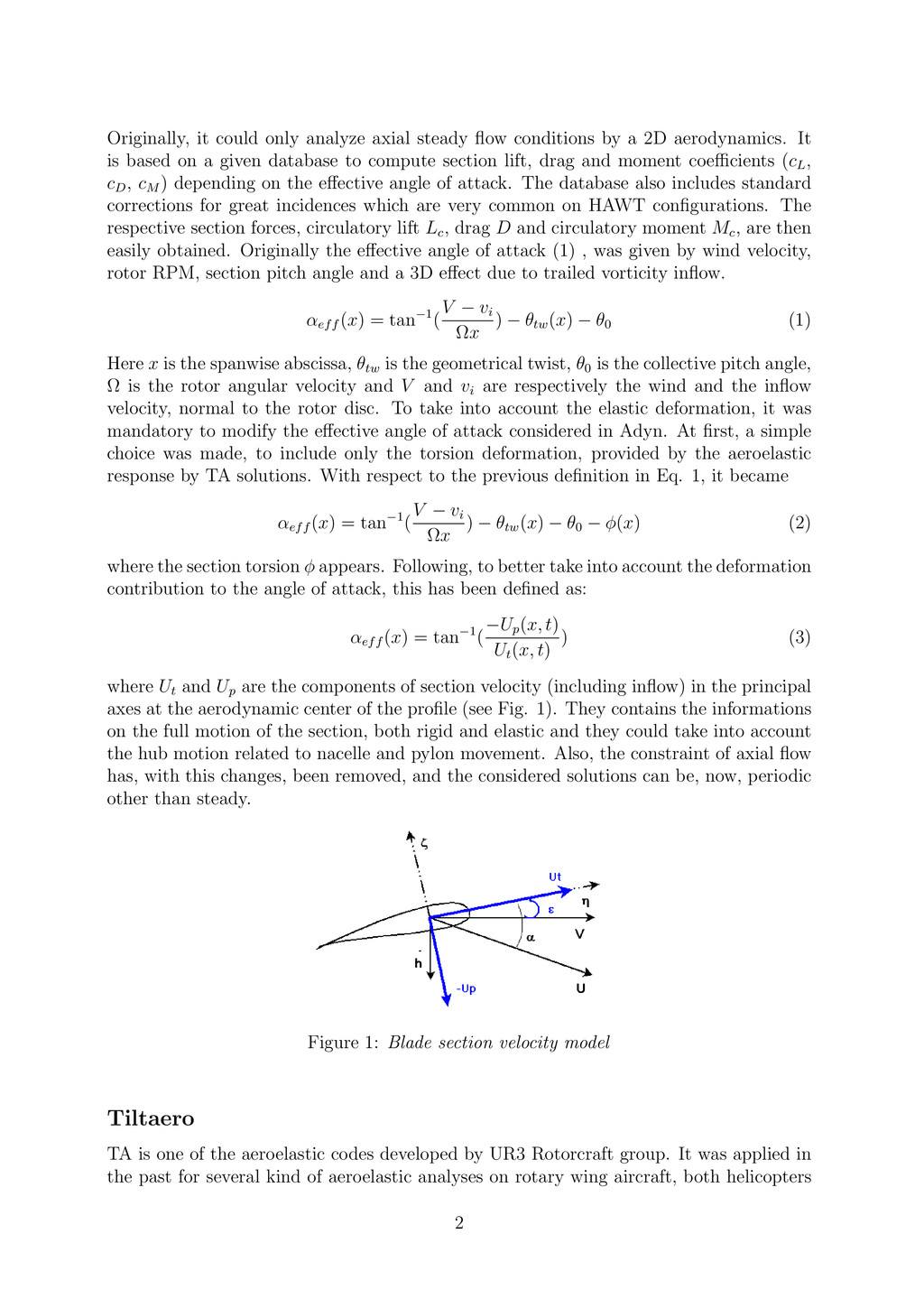
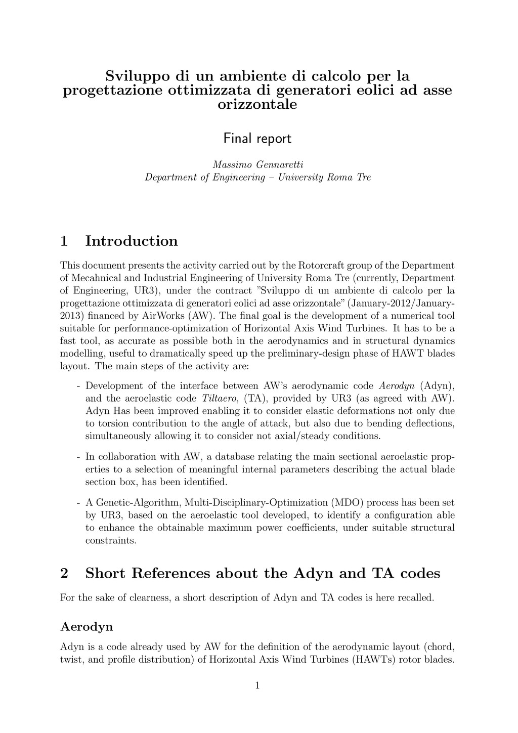