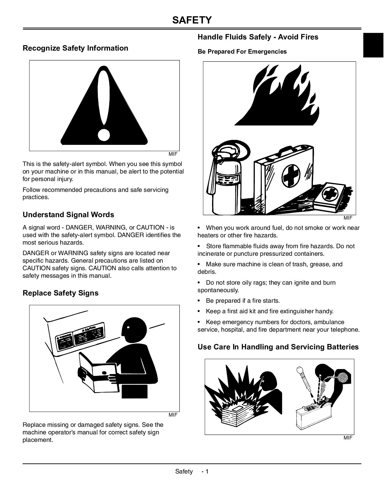
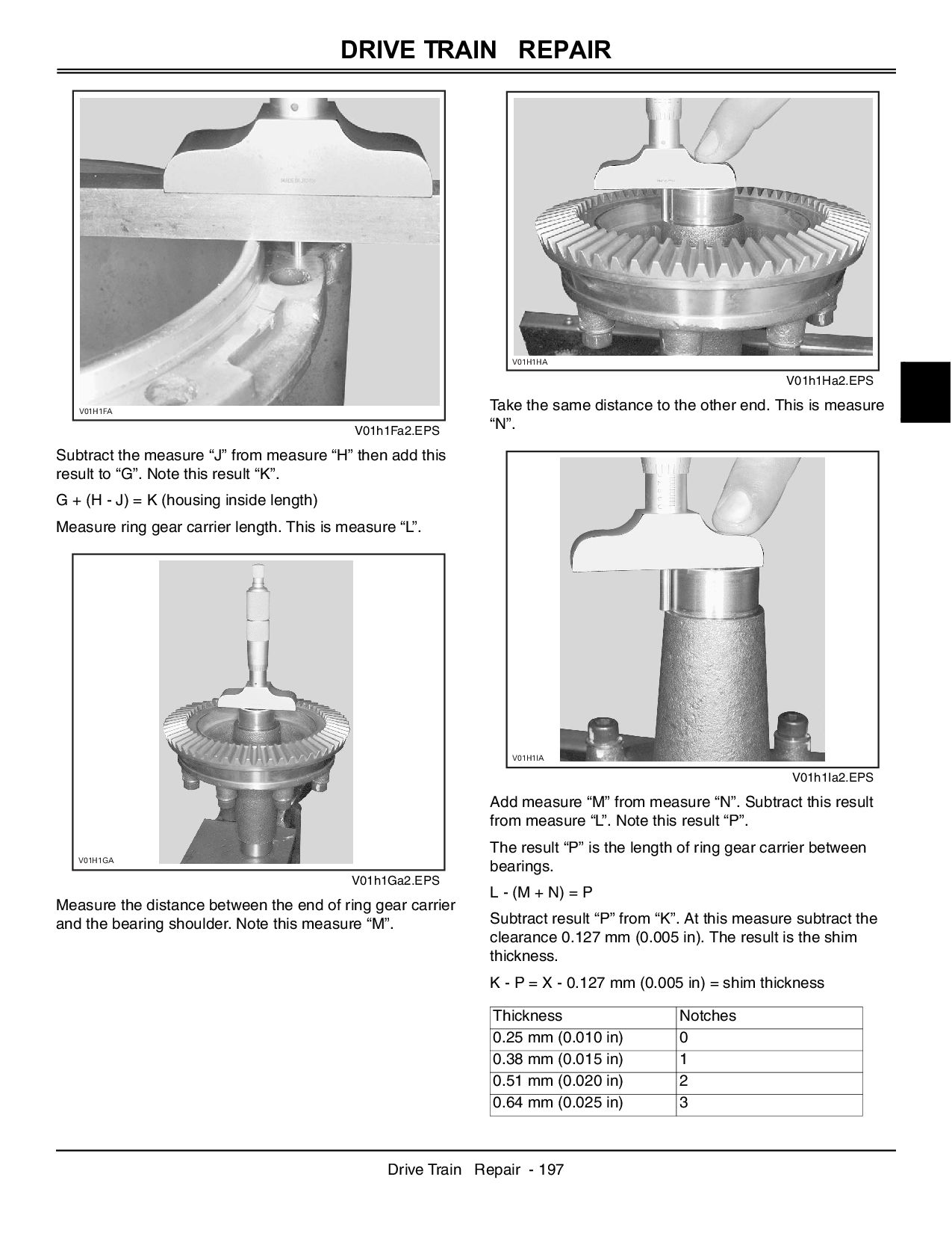
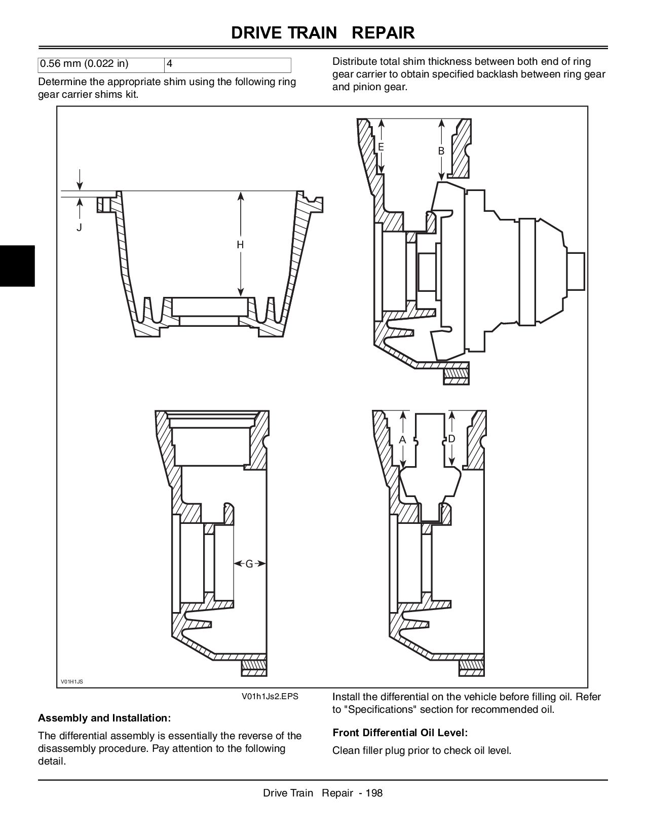
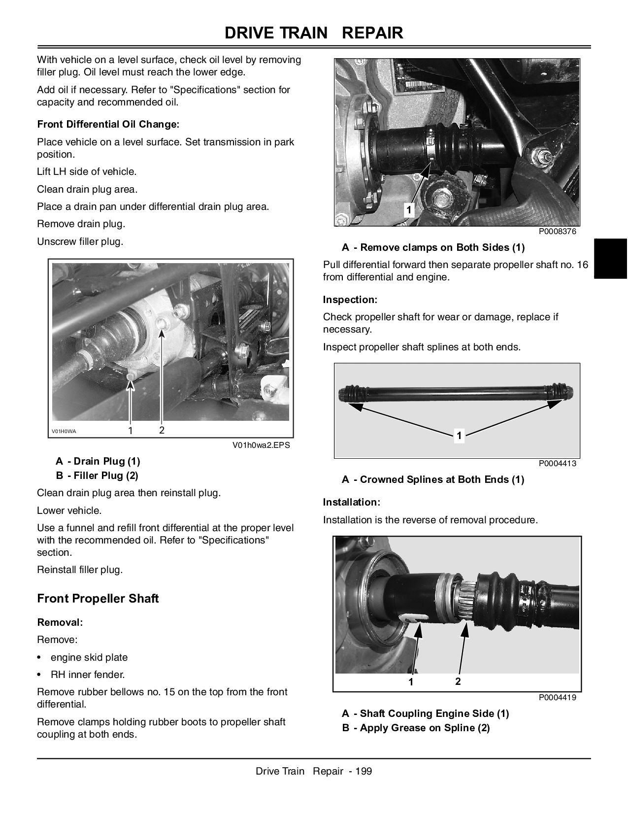
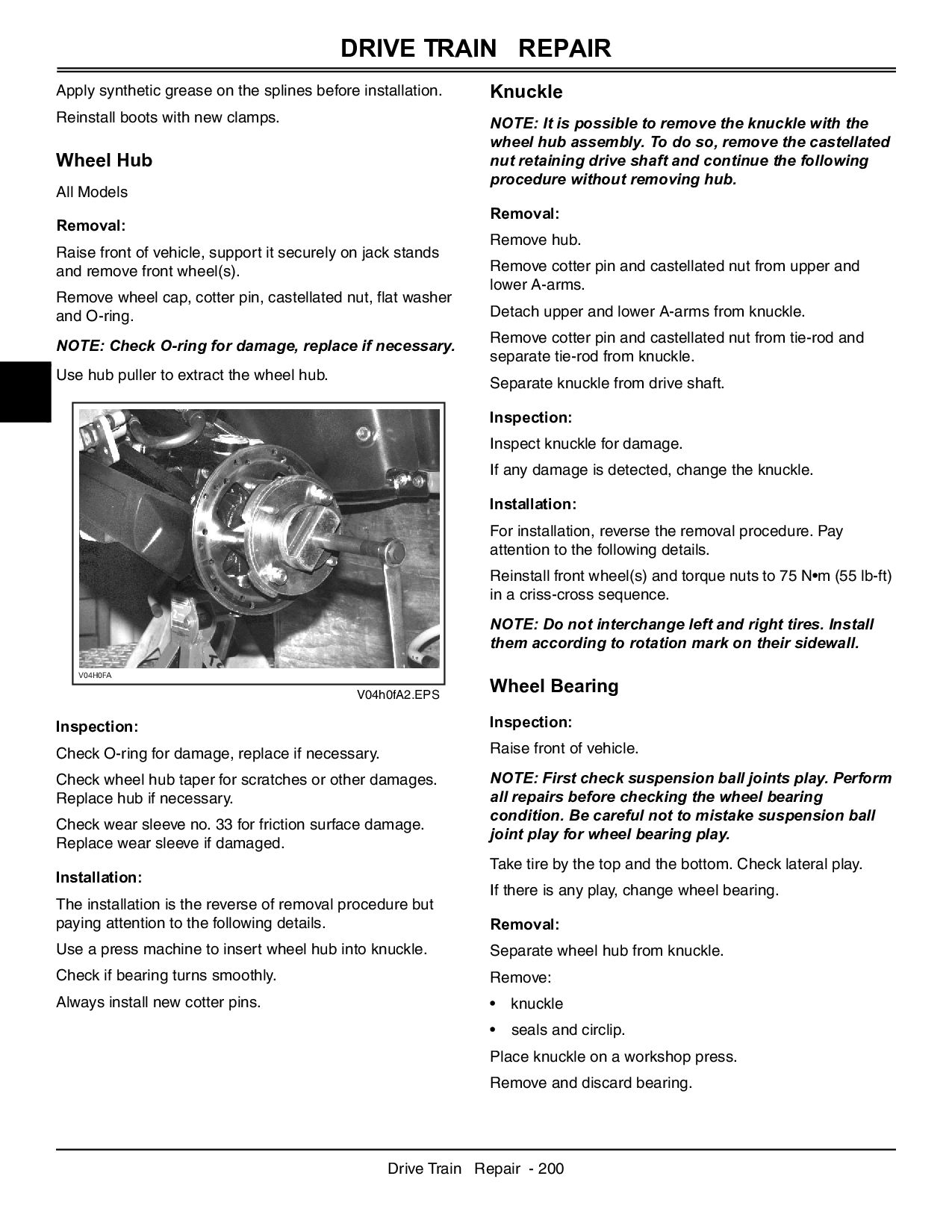
is the safety-alert symbol. When you see this symbol on your machine or in this manual, be alert to the potential for personal injury. Follow recommended precautions and safe servicing practices. Understand Signal Words A signal word - DANGER, WARNING, or CAUTION - is used with the safety-alert symbol. DANGER identifies the most serious hazards. DANGER or WARNING safety signs are located near specific hazards. General precautions are listed on CAUTION safety signs. CAUTION also calls attention to safety messages in this manual. Replace Safety Signs MIF Replace missing or damaged safety signs. See the machine operator’s manual for correct safety sign placement. Handle Fluids Safely - Avoid Fires Be Prepared For Emergencies MIF • When you work around fuel, do not smoke or work near heaters or other fire hazards. • Store flammable fluids away from fire hazards. Do not incinerate or puncture pressurized containers. • Make sure machine is clean of trash, grease, and debris. • Do not store oily rags; they can ignite and burn spontaneously. • Be prepared if a fire starts. • Keep a first aid kit and fire extinguisher handy. • Keep emergency numbers for doctors, ambulance service, hospital, and fire department near your telephone. Use Care In Handling and Servicing Batteries MIF
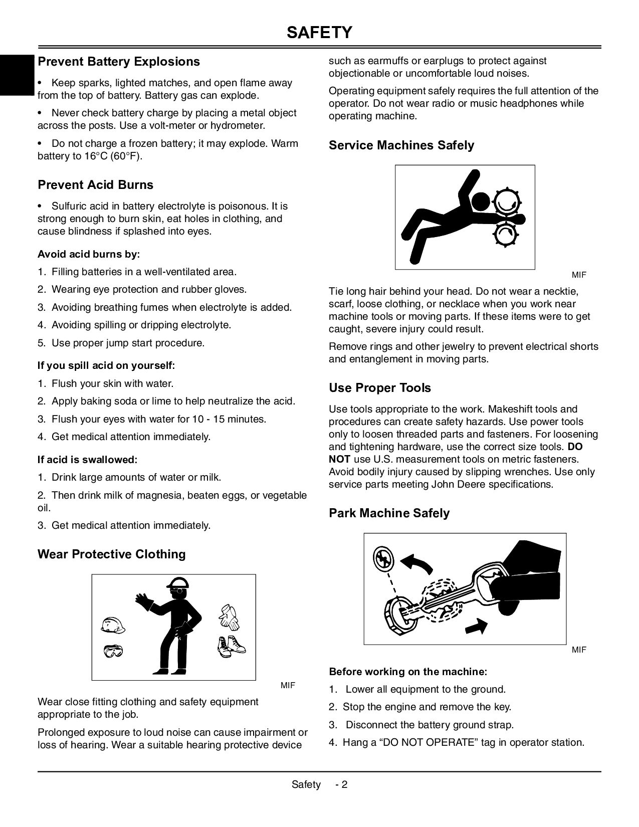
lighted matches, and open flame away from the top of battery. Battery gas can explode. • Never check battery charge by placing a metal object across the posts. Use a volt-meter or hydrometer. • Do not charge a frozen battery; it may explode. Warm battery to 16°C (60°F). Prevent Acid Burns • Sulfuric acid in battery electrolyte is poisonous. It is strong enough to burn skin, eat holes in clothing, and cause blindness if splashed into eyes. Avoid acid burns by: 1. Filling batteries in a well-ventilated area. 2. Wearing eye protection and rubber gloves. 3. Avoiding breathing fumes when electrolyte is added. 4. Avoiding spilling or dripping electrolyte. 5. Use proper jump start procedure. If you spill acid on yourself: 1. Flush your skin with water. 2. Apply baking soda or lime to help neutralize the acid. 3. Flush your eyes with water for 10 - 15 minutes. 4. Get medical attention immediately. If acid is swallowed: 1. Drink large amounts of water or milk. 2. Then drink milk of magnesia, beaten eggs, or vegetable oil. 3. Get medical attention immediately. Wear Protective Clothing MIF Wear close fitting clothing and safety equipment appropriate to the job. Prolonged exposure to loud noise can cause impairment or loss of hearing. Wear a suitable hearing protective device such as earmuffs or earplugs to protect against objectionable or uncomfortable loud noises. Operating equipment safely requires the full attention of the operator. Do not wear radio or music headphones while operating machine. Service Machines Safely MIF Tie long hair behind your head. Do not wear a necktie, scarf, loose clothing, or necklace when you work near machine tools or moving parts. If these items were to get caught, severe injury could result. Remove rings and other jewelry to prevent electrical shorts and entanglement in moving parts. Use Proper Tools Use tools appropriate to the work. Makeshift tools and procedures can create safety hazards. Use power tools only to loosen threaded parts and fasteners. For loosening and tightening hardware, use the correct size tools. DO NOT use U.S. measurement tools on metric fasteners. Avoid bodily injury caused by slipping wrenches. Use only service parts meeting John Deere specifications. Park Machine Safely MIF Before working on the machine: 1. Lower all equipment to the ground. 2. Stop the engine and remove the key. 3. Disconnect the battery ground strap. 4. Hang a “DO NOT OPERATE” tag in operator station.
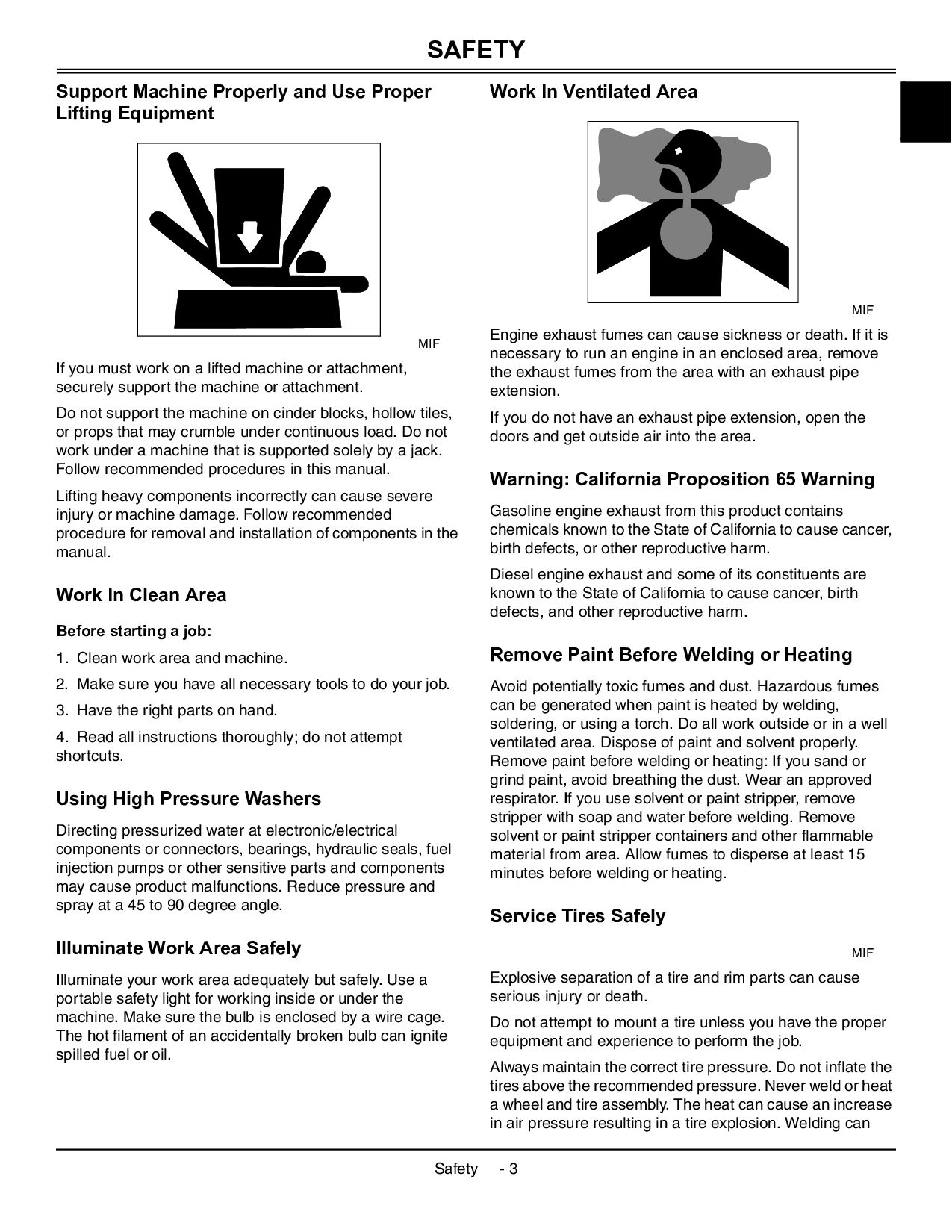
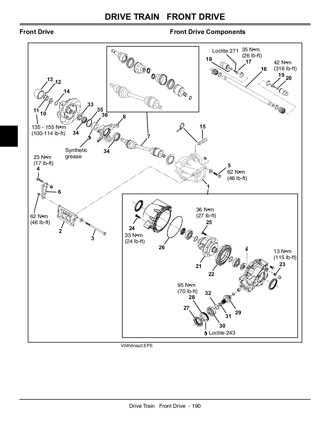
Lifting Equipment MIF If you must work on a lifted machine or attachment, securely support the machine or attachment. Do not support the machine on cinder blocks, hollow tiles, or props that may crumble under continuous load. Do not work under a machine that is supported solely by a jack. Follow recommended procedures in this manual. Lifting heavy components incorrectly can cause severe injury or machine damage. Follow recommended procedure for removal and installation of components in the manual. Work In Clean Area Before starting a job: 1. Clean work area and machine. 2. Make sure you have all necessary tools to do your job. 3. Have the right parts on hand. 4. Read all instructions thoroughly; do not attempt shortcuts. Using High Pressure Washers Directing pressurized water at electronic/electrical components or connectors, bearings, hydraulic seals, fuel injection pumps or other sensitive parts and components may cause product malfunctions. Reduce pressure and spray at a 45 to 90 degree angle. Illuminate Work Area Safely Illuminate your work area adequately but safely. Use a portable safety light for working inside or under the machine. Make sure the bulb is enclosed by a wire cage. The hot filament of an accidentally broken bulb can ignite spilled fuel or oil. Work In Ventilated Area MIF Engine exhaust fumes can cause sickness or death. If it is necessary to run an engine in an enclosed area, remove the exhaust fumes from the area with an exhaust pipe extension. If you do not have an exhaust pipe extension, open the doors and get outside air into the area. Warning: California Proposition 65 Warning Gasoline engine exhaust from this product contains chemicals known to the State of California to cause cancer, birth defects, or other reproductive harm. Diesel engine exhaust and some of its constituents are known to the State of California to cause cancer, birth defects, and other reproductive harm. Remove Paint Before Welding or Heating Avoid potentially toxic fumes and dust. Hazardous fumes can be generated when paint is heated by welding, soldering, or using a torch. Do all work outside or in a well ventilated area. Dispose of paint and solvent properly. Remove paint before welding or heating: If you sand or grind paint, avoid breathing the dust. Wear an approved respirator. If you use solvent or paint stripper, remove stripper with soap and water before welding. Remove solvent or paint stripper containers and other flammable material from area. Allow fumes to disperse at least 15 minutes before welding or heating. Service Tires Safely MIF Explosive separation of a tire and rim parts can cause serious injury or death. Do not attempt to mount a tire unless you have the proper equipment and experience to perform the job. Always maintain the correct tire pressure. Do not inflate the tires above the recommended pressure. Never weld or heat a wheel and tire assembly. The heat can cause an increase in air pressure resulting in a tire explosion. Welding can
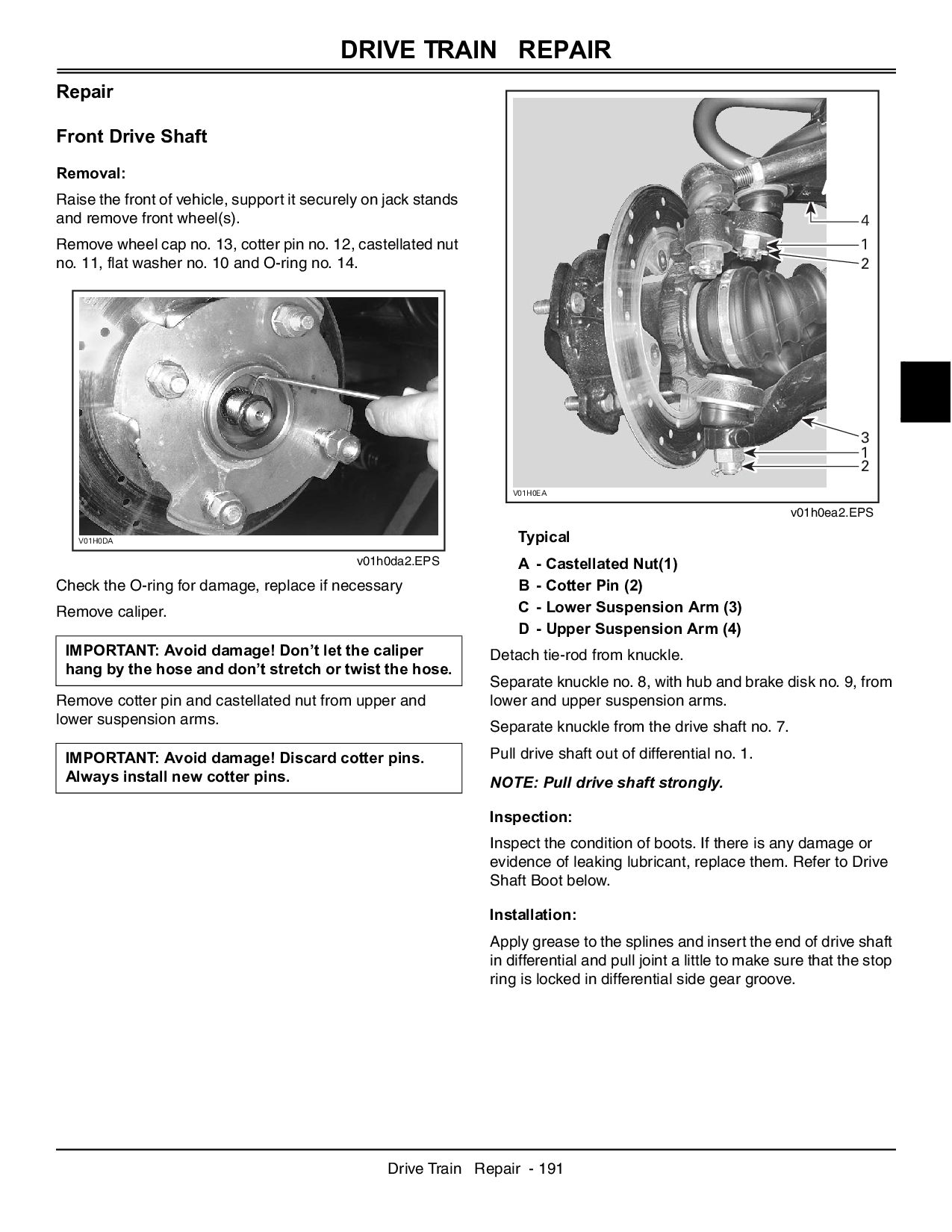
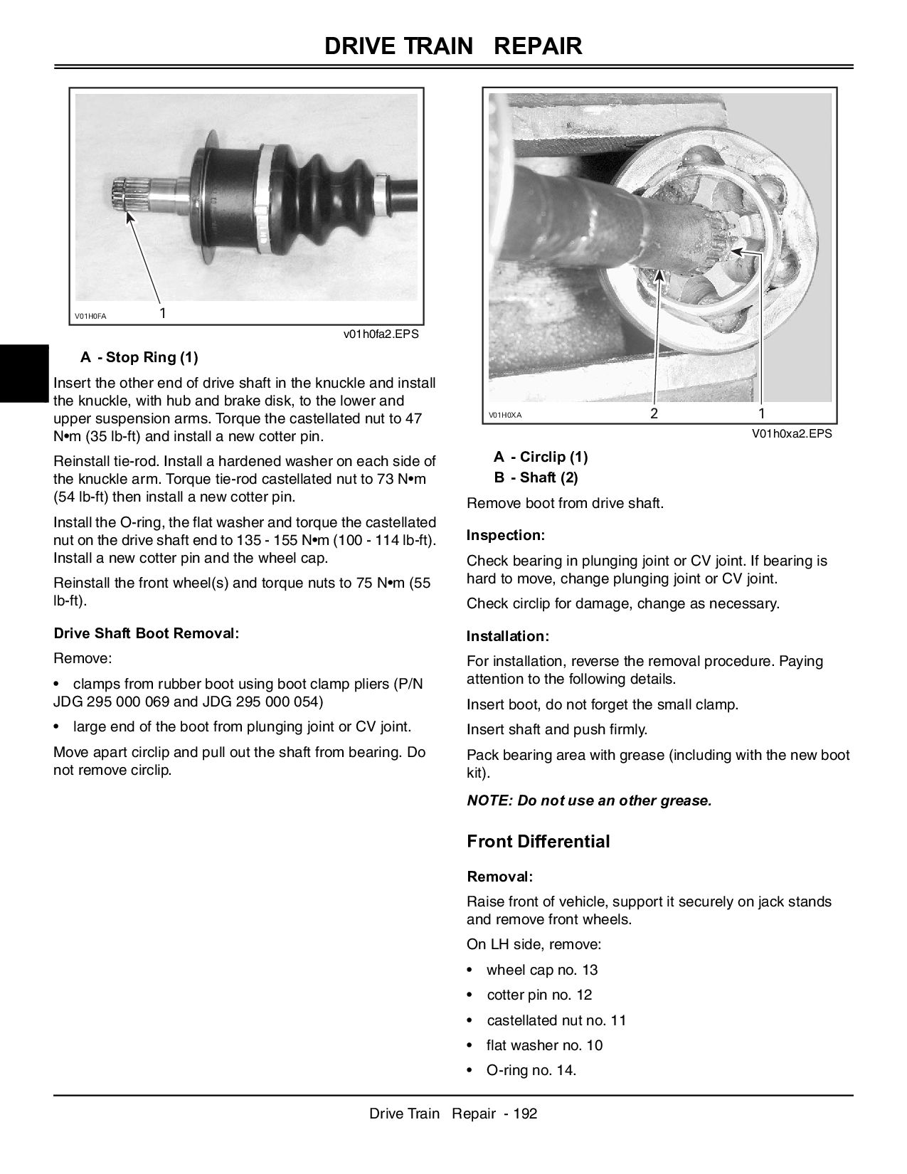
Drive Shaft Removal: Raise the front of vehicle, support it securely on jack stands and remove front wheel(s). Remove wheel cap no. 13, cotter pin no. 12, castellated nut no. 11, flat washer no. 10 and O-ring no. 14. v01h0da2.EPS Check the O-ring for damage, replace if necessary Remove caliper. Remove cotter pin and castellated nut from upper and lower suspension arms. v01h0ea2.EPS Typical A - Castellated Nut(1) B - Cotter Pin (2) C - Lower Suspension Arm (3) D - Upper Suspension Arm (4) Detach tie-rod from knuckle. Separate knuckle no. 8, with hub and brake disk no. 9, from lower and upper suspension arms. Separate knuckle from the drive shaft no. 7. Pull drive shaft out of differential no. 1. NOTE: Pull drive shaft strongly. Inspection: Inspect the condition of boots. If there is any damage or evidence of leaking lubricant, replace them. Refer to Drive Shaft Boot below. Installation: Apply grease to the splines and insert the end of drive shaft in differential and pull joint a little to make sure that the stop ring is locked in differential side gear groove. IMPORTANT: Avoid damage! Don’t let the caliper hang by the hose and don’t stretch or twist the hose. IMPORTANT: Avoid damage! Discard cotter pins. Always install new cotter pins. V01H0DA 4 V01H0EA 1 2 3 1 2
- Stop Ring (1) Insert the other end of drive shaft in the knuckle and install the knuckle, with hub and brake disk, to the lower and upper suspension arms. Torque the castellated nut to 47 N•m (35 lb-ft) and install a new cotter pin. Reinstall tie-rod. Install a hardened washer on each side of the knuckle arm. Torque tie-rod castellated nut to 73 N•m (54 lb-ft) then install a new cotter pin. Install the O-ring, the flat washer and torque the castellated nut on the drive shaft end to 135 - 155 N•m (100 - 114 lb-ft). Install a new cotter pin and the wheel cap. Reinstall the front wheel(s) and torque nuts to 75 N•m (55 lb-ft). Drive Shaft Boot Removal: Remove: • clamps from rubber boot using boot clamp pliers (P/N JDG 295 000 069 and JDG 295 000 054) • large end of the boot from plunging joint or CV joint. Move apart circlip and pull out the shaft from bearing. Do not remove circlip. V01h0xa2.EPS A - Circlip (1) B - Shaft (2) Remove boot from drive shaft. Inspection: Check bearing in plunging joint or CV joint. If bearing is hard to move, change plunging joint or CV joint. Check circlip for damage, change as necessary. Installation: For installation, reverse the removal procedure. Paying attention to the following details. Insert boot, do not forget the small clamp. Insert shaft and push firmly. Pack bearing area with grease (including with the new boot kit). NOTE: Do not use an other grease. Front Differential Removal: Raise front of vehicle, support it securely on jack stands and remove front wheels. On LH side, remove: • wheel cap no. 13 • cotter pin no. 12 • castellated nut no. 11 • flat washer no. 10 • O-ring no. 14. V01H0FA 1 1 V01H0XA 2
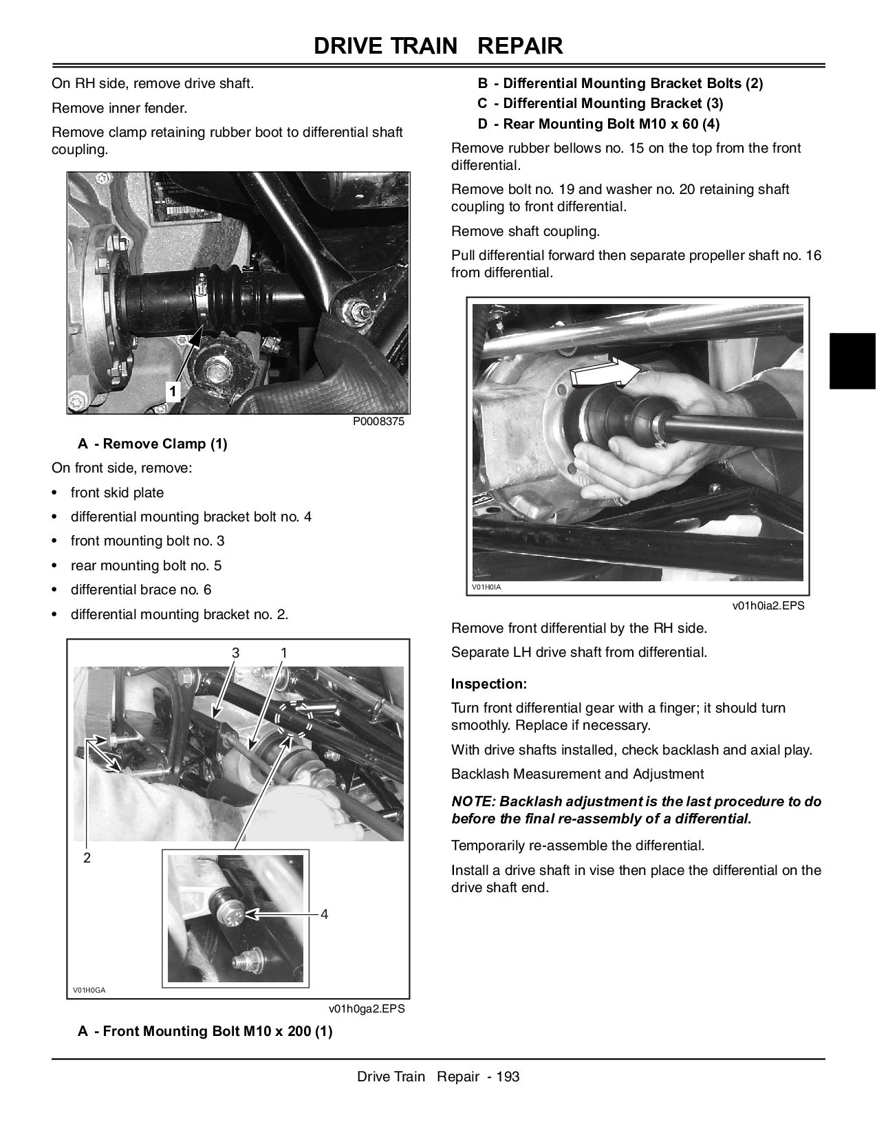
side, remove drive shaft. Remove inner fender. Remove clamp retaining rubber boot to differential shaft coupling. P0008375 A - Remove Clamp (1) On front side, remove: • front skid plate • differential mounting bracket bolt no. 4 • front mounting bolt no. 3 • rear mounting bolt no. 5 • differential brace no. 6 • differential mounting bracket no. 2. v01h0ga2.EPS A - Front Mounting Bolt M10 x 200 (1) B - Differential Mounting Bracket Bolts (2) C - Differential Mounting Bracket (3) D - Rear Mounting Bolt M10 x 60 (4) Remove rubber bellows no. 15 on the top from the front differential. Remove bolt no. 19 and washer no. 20 retaining shaft coupling to front differential. Remove shaft coupling. Pull differential forward then separate propeller shaft no. 16 from differential. v01h0ia2.EPS Remove front differential by the RH side. Separate LH drive shaft from differential. Inspection: Turn front differential gear with a finger; it should turn smoothly. Replace if necessary. With drive shafts installed, check backlash and axial play. Backlash Measurement and Adjustment NOTE: Backlash adjustment is the last procedure to do before the final re-assembly of a differential. Temporarily re-assemble the differential. Install a drive shaft in vise then place the differential on the drive shaft end. 1 V01H0GA 3 1 2 4 V01H0IA
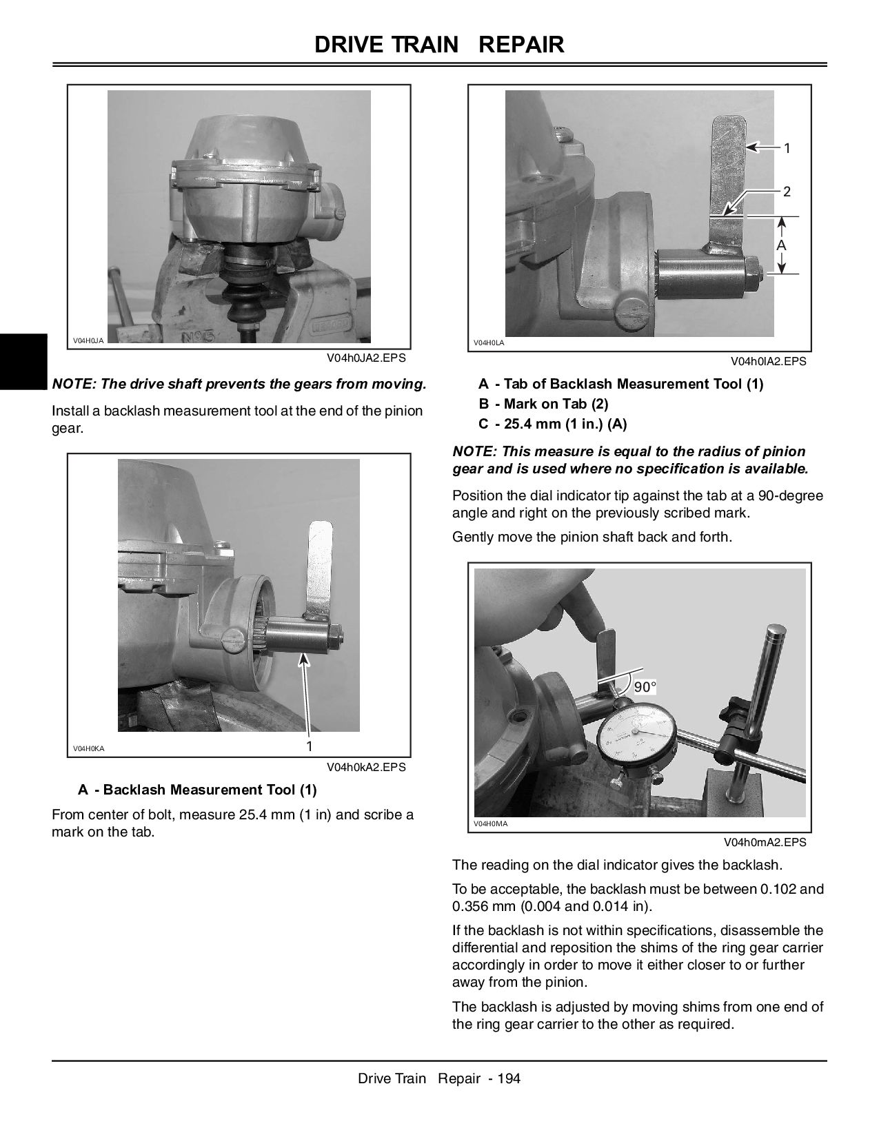
The drive shaft prevents the gears from moving. Install a backlash measurement tool at the end of the pinion gear. V04h0kA2.EPS A - Backlash Measurement Tool (1) From center of bolt, measure 25.4 mm (1 in) and scribe a mark on the tab. V04h0lA2.EPS A - Tab of Backlash Measurement Tool (1) B - Mark on Tab (2) C - 25.4 mm (1 in.) (A) NOTE: This measure is equal to the radius of pinion gear and is used where no specification is available. Position the dial indicator tip against the tab at a 90-degree angle and right on the previously scribed mark. Gently move the pinion shaft back and forth. V04h0mA2.EPS The reading on the dial indicator gives the backlash. To be acceptable, the backlash must be between 0.102 and 0.356 mm (0.004 and 0.014 in). If the backlash is not within specifications, disassemble the differential and reposition the shims of the ring gear carrier accordingly in order to move it either closer to or further away from the pinion. The backlash is adjusted by moving shims from one end of the ring gear carrier to the other as required. V04H0JA 1 V04H0KA A V04H0LA 1 2 V04H0MA 90°
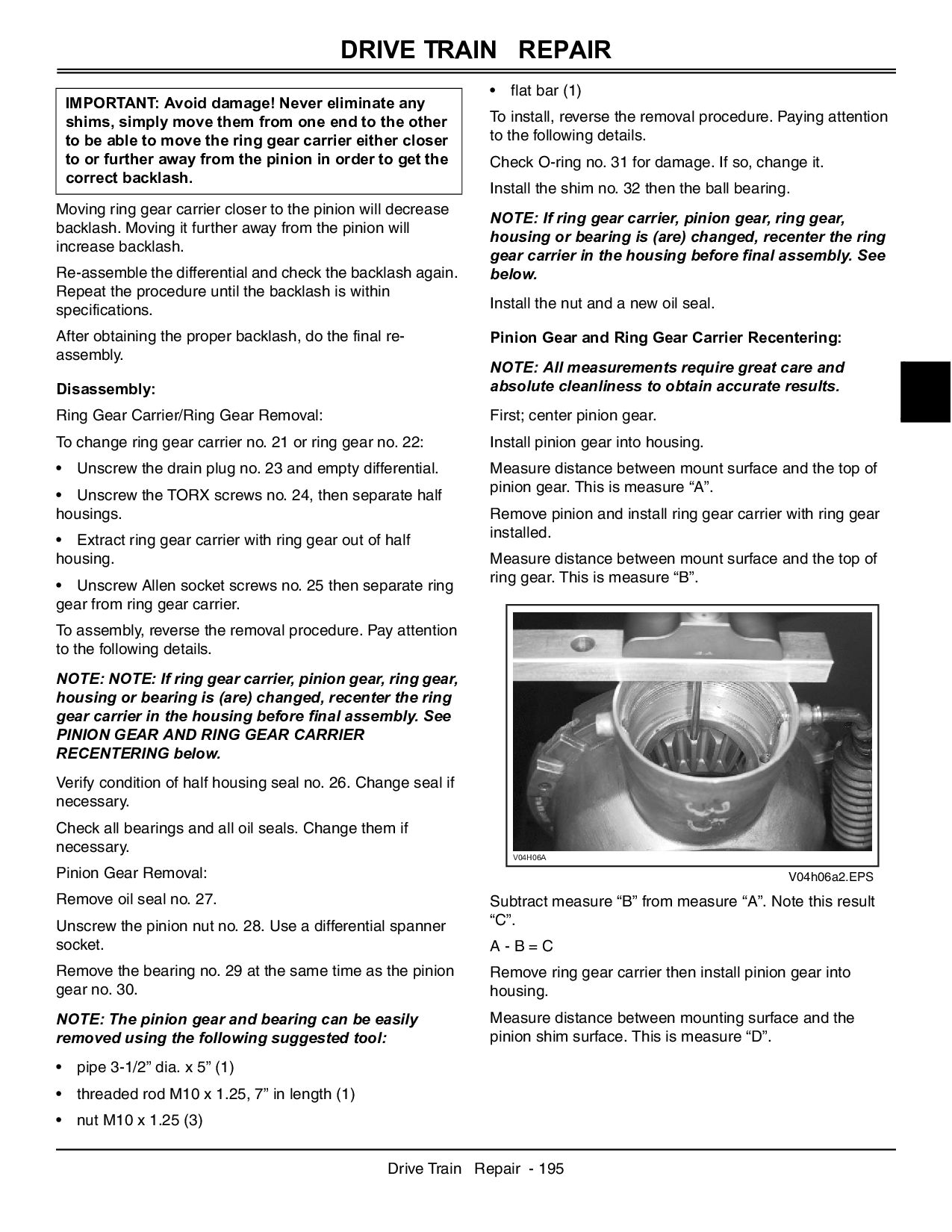
gear carrier closer to the pinion will decrease backlash. Moving it further away from the pinion will increase backlash. Re-assemble the differential and check the backlash again. Repeat the procedure until the backlash is within specifications. After obtaining the proper backlash, do the final re- assembly. Disassembly: Ring Gear Carrier/Ring Gear Removal: To change ring gear carrier no. 21 or ring gear no. 22: • Unscrew the drain plug no. 23 and empty differential. • Unscrew the TORX screws no. 24, then separate half housings. • Extract ring gear carrier with ring gear out of half housing. • Unscrew Allen socket screws no. 25 then separate ring gear from ring gear carrier. To assembly, reverse the removal procedure. Pay attention to the following details. NOTE: NOTE: If ring gear carrier, pinion gear, ring gear, housing or bearing is (are) changed, recenter the ring gear carrier in the housing before final assembly. See PINION GEAR AND RING GEAR CARRIER RECENTERING below. Verify condition of half housing seal no. 26. Change seal if necessary. Check all bearings and all oil seals. Change them if necessary. Pinion Gear Removal: Remove oil seal no. 27. Unscrew the pinion nut no. 28. Use a differential spanner socket. Remove the bearing no. 29 at the same time as the pinion gear no. 30. NOTE: The pinion gear and bearing can be easily removed using the following suggested tool: • pipe 3-1/2” dia. x 5” (1) • threaded rod M10 x 1.25, 7” in length (1) • nut M10 x 1.25 (3) • flat bar (1) To install, reverse the removal procedure. Paying attention to the following details. Check O-ring no. 31 for damage. If so, change it. Install the shim no. 32 then the ball bearing. NOTE: If ring gear carrier, pinion gear, ring gear, housing or bearing is (are) changed, recenter the ring gear carrier in the housing before final assembly. See below. Install the nut and a new oil seal. Pinion Gear and Ring Gear Carrier Recentering: NOTE: All measurements require great care and absolute cleanliness to obtain accurate results. First; center pinion gear. Install pinion gear into housing. Measure distance between mount surface and the top of pinion gear. This is measure “A”. Remove pinion and install ring gear carrier with ring gear installed. Measure distance between mount surface and the top of ring gear. This is measure “B”. V04h06a2.EPS Subtract measure “B” from measure “A”. Note this result “C”. A - B = C Remove ring gear carrier then install pinion gear into housing. Measure distance between mounting surface and the pinion shim surface. This is measure “D”. IMPORTANT: Avoid damage! Never eliminate any shims, simply move them from one end to the other to be able to move the ring gear carrier either closer to or further away from the pinion in order to get the correct backlash. V04H06A
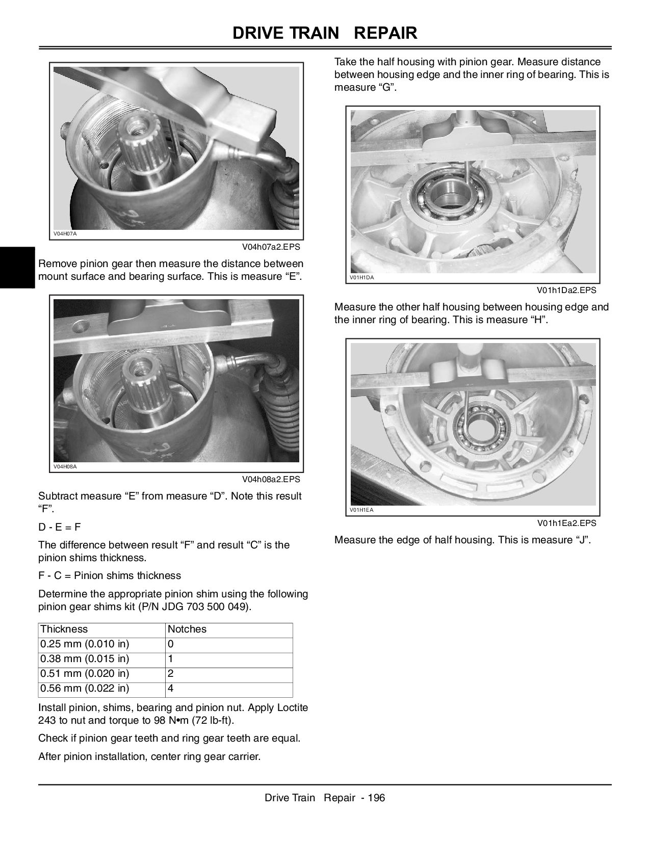
pinion gear then measure the distance between mount surface and bearing surface. This is measure “E”. V04h08a2.EPS Subtract measure “E” from measure “D”. Note this result “F”. D - E = F The difference between result “F” and result “C” is the pinion shims thickness. F - C = Pinion shims thickness Determine the appropriate pinion shim using the following pinion gear shims kit (P/N JDG 703 500 049). Install pinion, shims, bearing and pinion nut. Apply Loctite 243 to nut and torque to 98 N•m (72 lb-ft). Check if pinion gear teeth and ring gear teeth are equal. After pinion installation, center ring gear carrier. Take the half housing with pinion gear. Measure distance between housing edge and the inner ring of bearing. This is measure “G”. V01h1Da2.EPS Measure the other half housing between housing edge and the inner ring of bearing. This is measure “H”. V01h1Ea2.EPS Measure the edge of half housing. This is measure “J”. Thickness Notches 0.25 mm (0.010 in) 0 0.38 mm (0.015 in) 1 0.51 mm (0.020 in) 2 0.56 mm (0.022 in) 4 V04H07A V04H08A V01H1DA V01H1EA
the measure “J” from measure “H” then add this result to “G”. Note this result “K”. G + (H - J) = K (housing inside length) Measure ring gear carrier length. This is measure “L”. V01h1Ga2.EPS Measure the distance between the end of ring gear carrier and the bearing shoulder. Note this measure “M”. V01h1Ha2.EPS Take the same distance to the other end. This is measure “N”. V01h1Ia2.EPS Add measure “M” from measure “N”. Subtract this result from measure “L”. Note this result “P”. The result “P” is the length of ring gear carrier between bearings. L - (M + N) = P Subtract result “P” from “K”. At this measure subtract the clearance 0.127 mm (0.005 in). The result is the shim thickness. K - P = X - 0.127 mm (0.005 in) = shim thickness V01H1FA V01H1GA Thickness Notches 0.25 mm (0.010 in) 0 0.38 mm (0.015 in) 1 0.51 mm (0.020 in) 2 0.64 mm (0.025 in) 3 V01H1HA V01H1IA
appropriate shim using the following ring gear carrier shims kit. Distribute total shim thickness between both end of ring gear carrier to obtain specified backlash between ring gear and pinion gear. V01h1Js2.EPS Assembly and Installation: The differential assembly is essentially the reverse of the disassembly procedure. Pay attention to the following detail. Install the differential on the vehicle before filling oil. Refer to "Specifications" section for recommended oil. Front Differential Oil Level: Clean filler plug prior to check oil level. 0.56 mm (0.022 in) 4 V01H1JS H J E B A D G
on a level surface, check oil level by removing filler plug. Oil level must reach the lower edge. Add oil if necessary. Refer to "Specifications" section for capacity and recommended oil. Front Differential Oil Change: Place vehicle on a level surface. Set transmission in park position. Lift LH side of vehicle. Clean drain plug area. Place a drain pan under differential drain plug area. Remove drain plug. Unscrew filler plug. V01h0wa2.EPS A - Drain Plug (1) B - Filler Plug (2) Clean drain plug area then reinstall plug. Lower vehicle. Use a funnel and refill front differential at the proper level with the recommended oil. Refer to "Specifications" section. Reinstall filler plug. Front Propeller Shaft Removal: Remove: • engine skid plate • RH inner fender. Remove rubber bellows no. 15 on the top from the front differential. Remove clamps holding rubber boots to propeller shaft coupling at both ends. P0008376 A - Remove clamps on Both Sides (1) Pull differential forward then separate propeller shaft no. 16 from differential and engine. Inspection: Check propeller shaft for wear or damage, replace if necessary. Inspect propeller shaft splines at both ends. P0004413 A - Crowned Splines at Both Ends (1) Installation: Installation is the reverse of removal procedure. P0004419 A - Shaft Coupling Engine Side (1) B - Apply Grease on Spline (2) 2 V01H0WA 1 1 1 2 1
grease on the splines before installation. Reinstall boots with new clamps. Wheel Hub All Models Removal: Raise front of vehicle, support it securely on jack stands and remove front wheel(s). Remove wheel cap, cotter pin, castellated nut, flat washer and O-ring. NOTE: Check O-ring for damage, replace if necessary. Use hub puller to extract the wheel hub. V04h0fA2.EPS Inspection: Check O-ring for damage, replace if necessary. Check wheel hub taper for scratches or other damages. Replace hub if necessary. Check wear sleeve no. 33 for friction surface damage. Replace wear sleeve if damaged. Installation: The installation is the reverse of removal procedure but paying attention to the following details. Use a press machine to insert wheel hub into knuckle. Check if bearing turns smoothly. Always install new cotter pins. Knuckle NOTE: It is possible to remove the knuckle with the wheel hub assembly. To do so, remove the castellated nut retaining drive shaft and continue the following procedure without removing hub. Removal: Remove hub. Remove cotter pin and castellated nut from upper and lower A-arms. Detach upper and lower A-arms from knuckle. Remove cotter pin and castellated nut from tie-rod and separate tie-rod from knuckle. Separate knuckle from drive shaft. Inspection: Inspect knuckle for damage. If any damage is detected, change the knuckle. Installation: For installation, reverse the removal procedure. Pay attention to the following details. Reinstall front wheel(s) and torque nuts to 75 N•m (55 lb-ft) in a criss-cross sequence. NOTE: Do not interchange left and right tires. Install them according to rotation mark on their sidewall. Wheel Bearing Inspection: Raise front of vehicle. NOTE: First check suspension ball joints play. Perform all repairs before checking the wheel bearing condition. Be careful not to mistake suspension ball joint play for wheel bearing play. Take tire by the top and the bottom. Check lateral play. If there is any play, change wheel bearing. Removal: Separate wheel hub from knuckle. Remove: • knuckle • seals and circlip. Place knuckle on a workshop press. Remove and discard bearing. V04H0FA
new bearing in a freezer for 10 minutes before installation. Place the knuckle in oven to 100°C (212°F) for a half hour maximum to ease bearing installation. Press bearing into knuckle. When the knuckle is cold, apply synthetic grease on bearing then install the new seals. Install the other parts in the reverse order of removal procedure.


 sxedcwrfvk
 aleyda
 addyosmani
 inesmontani
 lauravandoore
 destraynor
 takai
 ipullrank
 coloredviolet
 chriscoyier
 khoart
 soudai