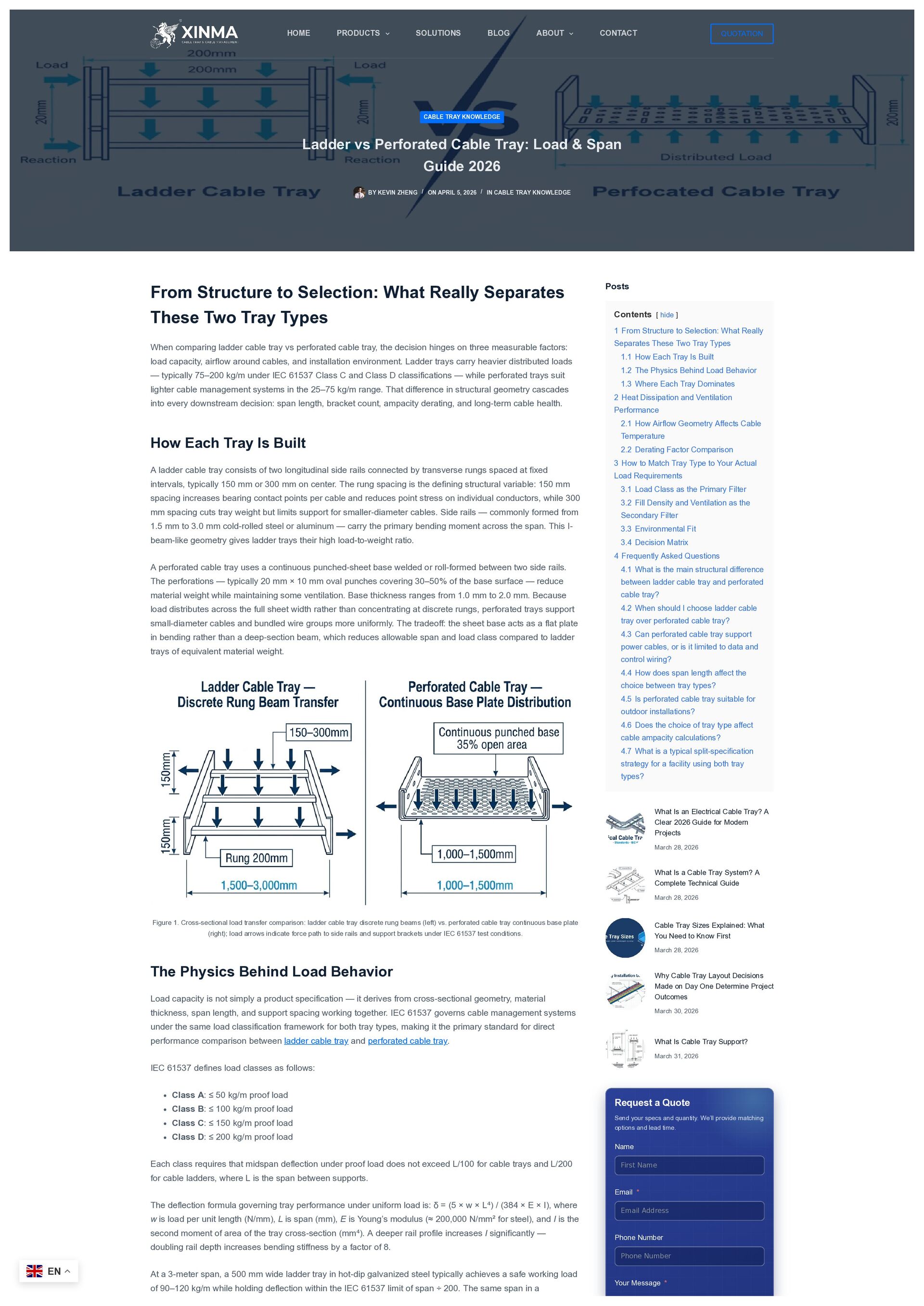
Types When comparing ladder cable tray vs perforated cable tray, the decision hinges on three measurable factors: load capacity, airflow around cables, and installation environment. Ladder trays carry heavier distributed loads — typically 75–200 kg/m under IEC 61537 Class C and Class D classifications — while perforated trays suit lighter cable management systems in the 25–75 kg/m range. That difference in structural geometry cascades into every downstream decision: span length, bracket count, ampacity derating, and long-term cable health. How Each Tray Is Built A ladder cable tray consists of two longitudinal side rails connected by transverse rungs spaced at fixed intervals, typically 150 mm or 300 mm on center. The rung spacing is the defining structural variable: 150 mm spacing increases bearing contact points per cable and reduces point stress on individual conductors, while 300 mm spacing cuts tray weight but limits support for smaller-diameter cables. Side rails — commonly formed from 1.5 mm to 3.0 mm cold-rolled steel or aluminum — carry the primary bending moment across the span. This I- beam-like geometry gives ladder trays their high load-to-weight ratio. A perforated cable tray uses a continuous punched-sheet base welded or roll-formed between two side rails. The perforations — typically 20 mm × 10 mm oval punches covering 30–50% of the base surface — reduce material weight while maintaining some ventilation. Base thickness ranges from 1.0 mm to 2.0 mm. Because load distributes across the full sheet width rather than concentrating at discrete rungs, perforated trays support small-diameter cables and bundled wire groups more uniformly. The tradeoff: the sheet base acts as a flat plate in bending rather than a deep-section beam, which reduces allowable span and load class compared to ladder trays of equivalent material weight. Figure 1. Cross-sectional load transfer comparison: ladder cable tray discrete rung beams (left) vs. perforated cable tray continuous base plate (right); load arrows indicate force path to side rails and support brackets under IEC 61537 test conditions. The Physics Behind Load Behavior Load capacity is not simply a product specification — it derives from cross-sectional geometry, material thickness, span length, and support spacing working together. IEC 61537 governs cable management systems under the same load classification framework for both tray types, making it the primary standard for direct performance comparison between ladder cable tray and perforated cable tray. IEC 61537 defines load classes as follows: Class A: ≤ 50 kg/m proof load Class B: ≤ 100 kg/m proof load Class C: ≤ 150 kg/m proof load Class D: ≤ 200 kg/m proof load Each class requires that midspan deflection under proof load does not exceed L/100 for cable trays and L/200 for cable ladders, where L is the span between supports. The deflection formula governing tray performance under uniform load is: δ = (5 × w × L⁴) / (384 × E × I), where w is load per unit length (N/mm), L is span (mm), E is Young’s modulus (≈ 200,000 N/mm² for steel), and I is the second moment of area of the tray cross-section (mm⁴). A deeper rail profile increases I significantly — doubling rail depth increases bending stiffness by a factor of 8. At a 3-meter span, a 500 mm wide ladder tray in hot-dip galvanized steel typically achieves a safe working load of 90–120 kg/m while holding deflection within the IEC 61537 limit of span ÷ 200. The same span in a Posts Contents [ hide ] 1 From Structure to Selection: What Really Separates These Two Tray Types 1.1 How Each Tray Is Built 1.2 The Physics Behind Load Behavior 1.3 Where Each Tray Dominates 2 Heat Dissipation and Ventilation Performance 2.1 How Airflow Geometry Affects Cable Temperature 2.2 Derating Factor Comparison 3 How to Match Tray Type to Your Actual Load Requirements 3.1 Load Class as the Primary Filter 3.2 Fill Density and Ventilation as the Secondary Filter 3.3 Environmental Fit 3.4 Decision Matrix 4 Frequently Asked Questions 4.1 What is the main structural difference between ladder cable tray and perforated cable tray? 4.2 When should I choose ladder cable tray over perforated cable tray? 4.3 Can perforated cable tray support power cables, or is it limited to data and control wiring? 4.4 How does span length affect the choice between tray types? 4.5 Is perforated cable tray suitable for outdoor installations? 4.6 Does the choice of tray type affect cable ampacity calculations? 4.7 What is a typical split-specification strategy for a facility using both tray types? What Is an Electrical Cable Tray? A Clear 2026 Guide for Modern Projects March 28, 2026 What Is a Cable Tray System? A Complete Technical Guide March 28, 2026 Cable Tray Sizes Explained: What You Need to Know First March 28, 2026 Why Cable Tray Layout Decisions Made on Day One Determine Project Outcomes March 30, 2026 What Is Cable Tray Support? March 31, 2026 Request a Quote Send your specs and quantity. We’ll provide matching options and lead time. First Name Email Address Phone Number Name Email * Phone Number Your Message * CABLE TRAY KNOWLEDGE Ladder vs Perforated Cable Tray: Load & Span Guide 2026 BY KEVIN ZHENG ON APRIL 5, 2026 IN CABLE TRAY KNOWLEDGE / / QUOTATION HOME PRODUCTS SOLUTIONS BLOG ABOUT CONTACT EN


 xmqjofficial
 inesmontani
 lynnandtonic
 marktimemedia
 chriscoyier
 mkilby
 kimpetersen
 signer
 yeseniaperezcruz
 speakerdeck
 thirion
 bryan
 akademiya2063