Upgrade to Pro — share decks privately, control downloads, hide ads and more …

E716_lec04

Ahmad El-Banna
November 04, 2014

 E716_lec04

7th Year, Integrated Technical Education Cluster AlAmeeria‎
lec#4, Mobile Communication Systems

Ahmad El-Banna

November 04, 2014
Tweet

More Decks by Ahmad El-Banna

Other Decks in Education

Transcript

  1. Lecture #4 Basic Concepts of Cellular Transmission (p1) Instructor: Dr.

    Ahmad El-Banna November 2014 E-716-A Mobile Communications Systems Integrated Technical Education Cluster At AlAmeeria‎ © Ahmad El-Banna
  2. Agenda Spread Spectrum Frequency hopping & Direct Sequence CDMA &

    OFDMA MIMO Technique Speech Compression 2 E-716-A, Lec#4 , Nov 2014 © Ahmad El-Banna
  3. Spread Spectrum • Input is fed into a channel encoder

    • Produces analog signal with narrow bandwidth • Signal is further modulated using sequence of digits • Spreading code or spreading sequence • Generated by pseudonoise*, or pseudo-random number generator • Effect of modulation is to increase bandwidth of signal to be transmitted • On receiving end, digit sequence is used to demodulate the spread spectrum signal • Signal is fed into a channel decoder to recover data 4 © Ahmad El-Banna E-716-A, Lec#4 , Nov 2014 * PN generator produces periodic sequence that appears to be random and is generated by an algorithm using initial seed
  4. Spread Spectrum .. • What can be gained from apparent

    waste of spectrum? • Immunity from various kinds of noise and multipath distortion. • Can be used for hiding and encrypting signals. • Several users can independently use the same higher bandwidth with very little interference (Example: CDMA) 5 © Ahmad El-Banna E-716-A, Lec#4 , Nov 2014
  5. Spreading and Frequency Selective Fading 6 © Ahmad El-Banna E-716-A,

    Lec#4 , Nov 2014 frequency channel quality 1 2 3 4 5 6 narrow band signal guard space narrowband channels 2 2 2 2 2 frequency channel quality 1 spread spectrum spread spectrum channels
  6. Frequency Hoping Spread Spectrum (FHSS) • Signal is broadcast over

    random series of radio frequencies • Signal hops from frequency to frequency at fixed intervals • Channel sequence dictated by spreading code • Receiver, hopping between frequencies in synchronization with transmitter, picks up message 8 © Ahmad El-Banna E-716-A, Lec#4 , Nov 2014
  7. FHSS.. • Two versions • Fast Hopping: several frequencies per

    user bit • Slow Hopping: several user bits per frequency 9 © Ahmad El-Banna E-716-A, Lec#4 , Nov 2014 user data slow hopping (3 bits/hop) fast hopping (3 hops/bit) 0 1 tb 0 1 1 t f f1 f2 f3 t td f f1 f2 f3 t td tb : bit period td : dwell time
  8. FHSS… • Advantages • frequency selective fading and interference limited

    to short period • simple implementation • uses only small portion of spectrum at any time • Resistant to jamming • Disadvantages • simpler to detect • not as robust as DSSS 10 © Ahmad El-Banna E-716-A, Lec#4 , Nov 2014
  9. Direct Sequence Spread Spectrum (DSSS) • Each bit in original

    signal is represented by multiple bits in the transmitted signal • The spreading code spreads the signal across a wider frequency band in direct proportion to the number of bits used. • One technique combines digital information stream with the spreading code bit stream using exclusive-OR 11 © Ahmad El-Banna E-716-A, Lec#4 , Nov 2014
  10. DSSS.. 12 © Ahmad El-Banna E-716-A, Lec#4 , Nov 2014

    • Advantages • reduces frequency selective fading • in cellular networks • base stations can use the same frequency range • several base stations can detect and recover the signal • soft handover • Disadvantages • precise power control necessary
  11. CDMA • CDMA (Code Division Multiple Access) • all terminals

    send on the same frequency probably at the same time and can use the whole bandwidth of the transmission channel • each sender has a unique random number, the sender XORs the signal with this random number • the receiver can “tune” into this signal if it knows the pseudo random number • Disadvantages: • higher complexity of a receiver (receiver cannot just listen into the medium and start receiving if there is a signal) • all signals should have the same strength at a receiver • Advantages: • all terminals can use the same frequency, no planning needed • huge code space (e.g. 232) compared to frequency space • interferences (e.g. white noise) is not coded • forward error correction and encryption can be easily integrated 14 © Ahmad El-Banna E-716-A, Lec#4 , Nov 2014
  12. CDMA in theory • Sender A • sends Ad =

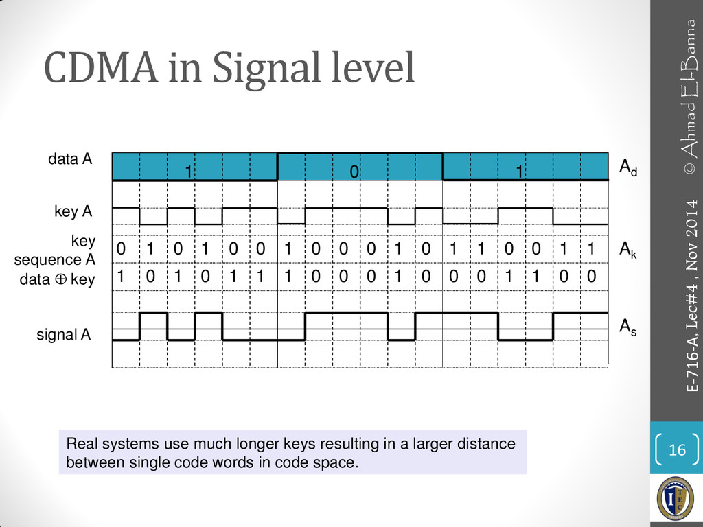
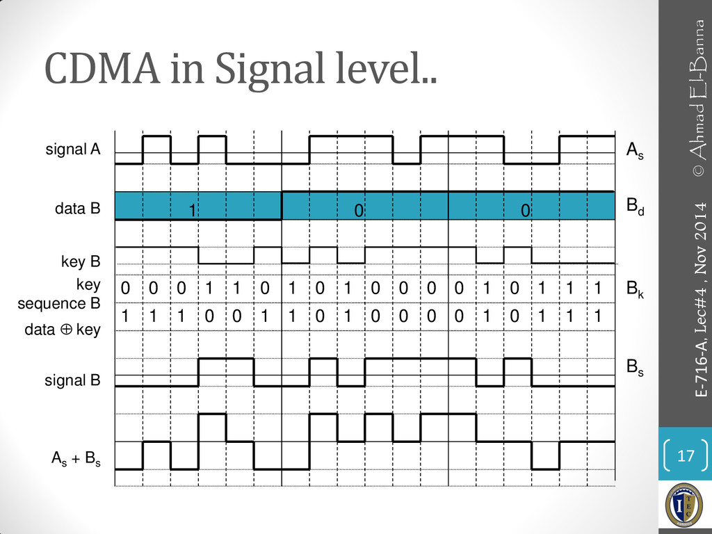
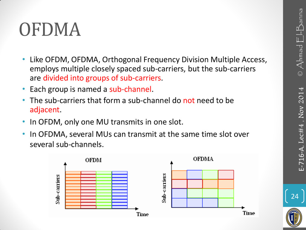
    1, key Ak = 010011 (assign: “0”= -1, “1”= +1) • sending signal As = Ad * Ak = (-1, +1, -1, -1, +1, +1) • Sender B • sends Bd = 0, key Bk = 110101 (assign: “0”= -1, “1”= +1) • sending signal Bs = Bd * Bk = (-1, -1, +1, -1, +1, -1) • Both signals superimpose in space • interference neglected (noise etc.) • As + Bs = (-2, 0, 0, -2, +2, 0) • Receiver wants to receive signal from sender A • apply key Ak bitwise (inner product) • Ae = (-2, 0, 0, -2, +2, 0)  Ak = 2 + 0 + 0 + 2 + 2 + 0 = 6 • result greater than 0, therefore, original bit was “1” • receiving B • Be = (-2, 0, 0, -2, +2, 0)  Bk = -2 + 0 + 0 - 2 - 2 + 0 = -6, i.e. “0” 15 © Ahmad El-Banna E-716-A, Lec#4 , Nov 2014
  13. CDMA in Signal level 16 © Ahmad El-Banna E-716-A, Lec#4

    , Nov 2014 data A key A signal A data  key key sequence A Real systems use much longer keys resulting in a larger distance between single code words in code space. 1 0 1 1 0 0 1 0 0 1 0 0 0 1 0 1 1 0 0 1 1 0 1 1 0 1 1 1 0 0 0 1 0 0 0 1 1 0 0 Ad Ak As
  14. CDMA in Signal level.. 17 © Ahmad El-Banna E-716-A, Lec#4

    , Nov 2014 signal A data B key B key sequence B signal B As + Bs data  key 1 0 0 0 0 0 1 1 0 1 0 1 0 0 0 0 1 0 1 1 1 1 1 1 0 0 1 1 0 1 0 0 0 0 1 0 1 1 1 Bd Bk Bs As
  15. CDMA in Signal level... 18 © Ahmad El-Banna E-716-A, Lec#4

    , Nov 2014 Ak (As + Bs ) * Ak integrator output comparator output As + Bs data A 1 0 1 1 0 1 Ad
  16. CDMA in Signal level.... 19 © Ahmad El-Banna E-716-A, Lec#4

    , Nov 2014 integrator output comparator output Bk (As + Bs ) * Bk As + Bs data B 1 0 0 1 0 0 Bd
  17. CDMA in Signal level..... 20 © Ahmad El-Banna E-716-A, Lec#4

    , Nov 2014 comparator output wrong key K integrator output (As + Bs ) * K As + Bs (0) (0) ?
  18. Comparison of S/T/F/C DMA 21 © Ahmad El-Banna E-716-A, Lec#4

    , Nov 2014 Approach SDMA TDMA FDMA CDMA Idea segment space into cells/sectors segment sending time into disjoint time-slots, demand driven or fixed patterns segment the frequency band into disjoint sub-bands spread the spectrum using orthogonal codes Terminals only one terminal can be active in one cell/one sector all terminals are active for short periods of time on the same frequency every terminal has its own frequency, uninterrupted all terminals can be active at the same place at the same moment, uninterrupted Signal separation cell structure, directed antennas synchronization in the time domain filtering in the frequency domain code plus special receivers Advantages very simple, increases capacity per km² established, fully digital, flexible simple, established, robust flexible, less frequency planning needed, soft handover Dis- advantages inflexible, antennas typically fixed guard space needed (multipath propagation), synchronization difficult inflexible, frequencies are a scarce resource complex receivers, needs more complicated power control for senders Comment only in combination with TDMA, FDMA or CDMA useful standard in fixed networks, together with FDMA/SDMA used in many mobile networks typically combined with TDMA (frequency hopping patterns) and SDMA (frequency reuse) still faces some problems, higher complexity, lowered expectations; will be integrated with TDMA/FDMA
  19. OFDM • OFDM, Orthogonal Frequency Division Multiplexing, is a special

    kind of FDM. • The spacing between carriers are such that they are orthogonal to one another meaning the peak of one sub-carrier coincides with the null of an adjacent sub-carrier. • Therefore no need of guard band between carriers and the result is saving of bandwidth. 22 © Ahmad El-Banna E-716-A, Lec#4 , Nov 2014
  20. OFDM.. • In an OFDM system, a very high rate

    data stream is divided into multiple parallel low rate data streams. • Each smaller data stream is then mapped to individual data sub- carrier and modulated using some PSK/QAM Modulation (QPSK, 16- QAM, 64-QAM). • OFDM needs less bandwidth than FDM to carry the same amount of information which results in higher spectral efficiency. • The effect of ISI (Inter Symbol Interference) is suppressed by virtue of a longer symbol period of the parallel OFDM subcarriers than a single carrier system and the use of a cyclic prefix (CP). 23 © Ahmad El-Banna E-716-A, Lec#4 , Nov 2014
  21. OFDMA • Like OFDM, OFDMA, Orthogonal Frequency Division Multiple Access,

    employs multiple closely spaced sub-carriers, but the sub-carriers are divided into groups of sub-carriers. • Each group is named a sub-channel. • The sub-carriers that form a sub-channel do not need to be adjacent. • In OFDM, only one MU transmits in one slot. • In OFDMA, several MUs can transmit at the same time slot over several sub-channels. 24 © Ahmad El-Banna E-716-A, Lec#4 , Nov 2014
  22. What is MIMO? • A traditional communications link, which we

    call a single-in-single-out (SISO) channel, has one transmitter and one receiver. • But instead of a single transmitter and a single receiver we can use several of each. • The SISO channel then becomes a multiple-in-multiple- out, or a MIMO channel; i.e. a channel that has multiple transmitters and multiple receivers. • MIMO offers a way to increase capacity without increasing power. 26 © Ahmad El-Banna E-716-A, Lec#4 , Nov 2014
  23. MIMO Forms/Topologies • SISO • SIMO • MISO • MIMO

    27 © Ahmad El-Banna E-716-A, Lec#4 , Nov 2014 S : Single M: Multiple I : Input O: Output
  24. MIMO Techniques • The MIMO design of a communications link

    can be classified in two main ways. • MIMO using diversity techniques • MIMO using spatial-multiplexing techniques • Diversity means that the same data has traveled through diverse paths to get to the receiver. • Diversity increases the reliability of communications. If one path is weak, then a copy of the data received on another path maybe just fine. • In spatial-multiplexing, we multiplex the data on the multiple channels. • It increases the data throughput or the capacity of the channel 28 © Ahmad El-Banna E-716-A, Lec#4 , Nov 2014
  25. Purpose and Examples • The compression of speech signals has

    many practical applications. • One example is in digital cellular technology where many users share the same frequency bandwidth. • Compression allows more users to share the system than otherwise possible. • Another example is in digital voice storage (e.g. answering machines). • For a given memory size, compression allows longer messages to be stored than otherwise. 30 © Ahmad El-Banna E-716-A, Lec#4 , Nov 2014 • The purpose of speech compression is to reduce the number of bits required to represent speech signals (by reducing redundancy) in order to minimize the requirement for transmission bandwidth
  26. Speech Signal Digitization • A) Sampling • B) Quantization •

    C) Coding 31 © Ahmad El-Banna E-716-A, Lec#4 , Nov 2014 • Digital speech signals are sampled at a rate of 8000 samples/sec. • Typically, each sample is represented by 8 bits. • Speech coders are of two types: • Waveform Coders • Time Domain: (PCM, ADPCM) • Frequency Domain: Sub-band coders, Adaptive transform coders • Vocoders • Linear Predictive Coders • Formant Coders
  27. Compression • The 8 bit sample to an uncompressed rate

    of 64 kbps (kbits/sec). • 8000(sample/sec) x 8(bit) = 64 kbps • With current compression techniques (all of which are lossy), it is possible to reduce the rate to 8 kbps with almost no perceptible loss in quality. • Further compression is possible at a cost of lower quality. • All of the current low-rate speech coders are based on the principle of linear predictive coding (LPC). 32 © Ahmad El-Banna E-716-A, Lec#4 , Nov 2014
  28. • For more details, refer to: • Chapter 2&3, J.

    Chiller, Mobile Communications, 2003. • Chapter 7, W. Stallings, Wireless Communications and Networks, 2005. • The lecture is available onlin e at: • https://speakerdeck.com/ahmad_elbanna • For inquires, send to: • [email protected] 33 E-716-A, Lec#4 , Nov 2014 © Ahmad El-Banna