$30 off During Our Annual Pro Sale. View Details »

Operating at force, power, and thermal limits in electrically-actuated commercial legged robots

Avik De
September 04, 2021
29

Operating at force, power, and thermal limits in electrically-actuated commercial legged robots

This talk was given at the IROS actuator workshop https://www.ram.eemcs.utwente.nl/gears-direct-drive-recent-trends-and-opportunities-actuation

Youtube link of me presenting the slides https://youtu.be/724g-ZmK0G8

Avik De

September 04, 2021
Tweet

Transcript

  1. Operating at force, power, and thermal limits in
    electrically-actuated commercial legged robots
    Avik De
    Co-founder & CTO, Ghost Robotics
    Previously: Postdoc @ Harvard, Ph.D. @ UPenn

    View Slide

  2. Bio-inspired robot locomotion
    Minitaur (6kg, 8dof direct drive)
    100mg 1g 10g 100g 1kg 10kg 100kg
    Jerboa (3kg, 4dof) Spirit 40 (12kg, 12dof)
    Vision 60 (43kg, 12dof)

    View Slide

  3. Ghost Robotics
    Vision 60, Spirit 40
    • Company: ~20 people, 
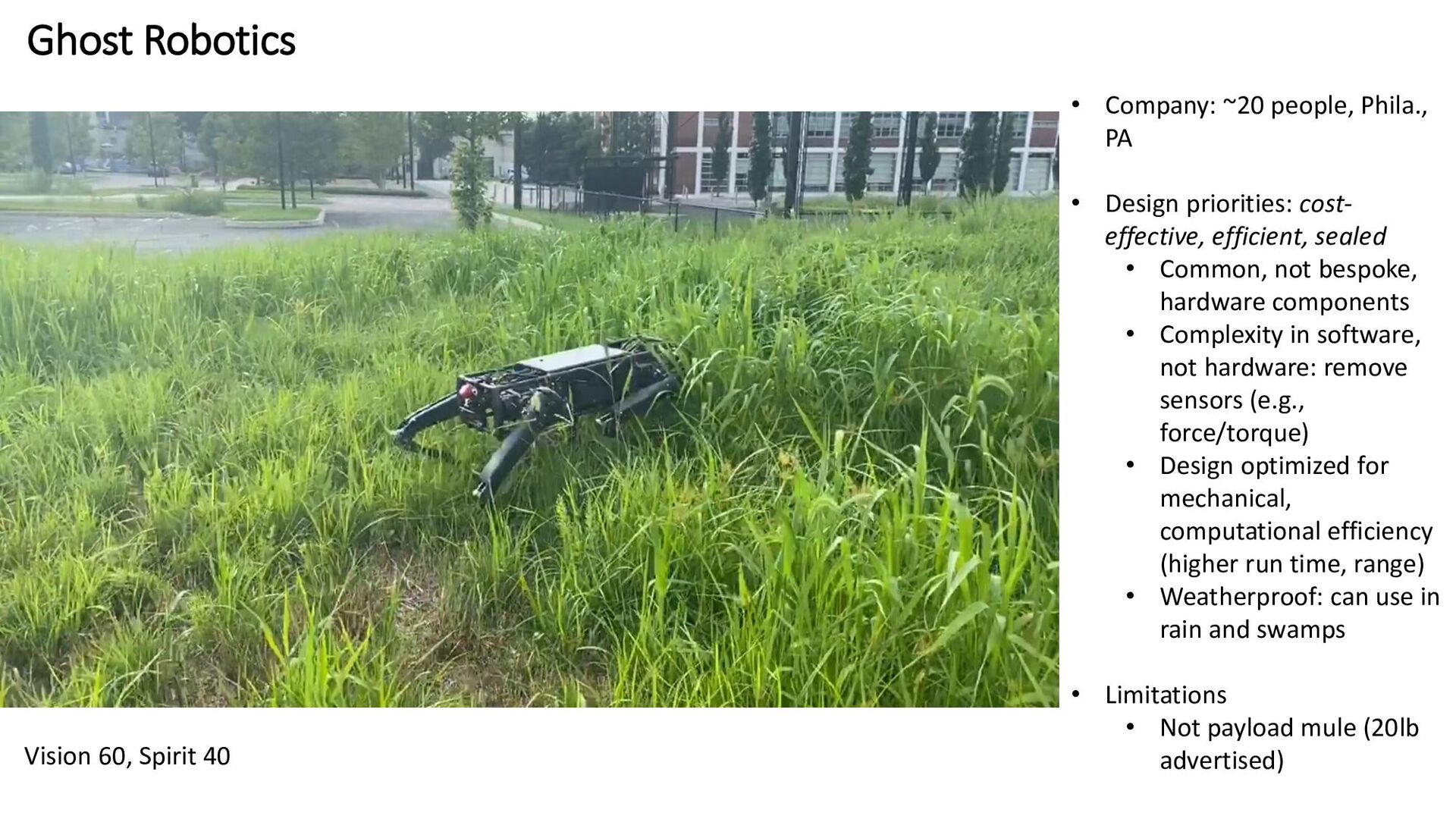
Phila.,
    PA
    • Design priorities: cost-
    effective, efficient, sealed
    • Common, not bespoke,
    hardware components
    • Complexity in software,
    not hardware: remove
    sensors (e.g.,
    force/torque)
    • Design optimized for
    mechanical,
    computational efficiency
    (higher run time, range)
    • Weatherproof: can use in
    rain and swamps
    • Limitations
    • Not payload mule (20lb
    advertised)

    View Slide

  4. Applications: mobile sensing, mobile manipulation
    Persistent security with autonomous charging
    CBRN/EOD

    View Slide

  5. Optimize design for fundamental constraints: force, power
    Power breakdown Power (W)
    Motors 180--280
    Low level electronics 10
    Blind locomotion <1
    Gait planner <5
    Autonomy 15
    • “Autonomy” requires power autonomy
    • Maximize range before recharge
    • Vision 60 total CoT 0.46—0.8, depending on
    terrain
    • Also bandwidth, transparency
    Minitaur: update rate 1000 Hz

    View Slide

  6. Motivation: analytically-guided design
    Motor
    Motor controller
    Gearbox
    Compliant element
    Leg kinematics
    Dynamic task
    specification for gearbox
    selection
    e.g. [De et al (2011)]
    e.g. [Hollerbach (1991)]
    [Wensing (2017)]
    Huge amount of past
    work…
    𝑢, 𝑘𝑜
    , …
    𝑟, 𝑑, 𝑙, … , 𝐿, 𝑅, …
    𝐺, 𝐽𝐺
    𝑘, 𝑏, …
    𝑙𝑖
    , …
    Platform morphology
    𝑑, 𝜅, 𝜌𝑡
    , 𝑚𝑡
    , … e.g. [De et al (2018)]

    View Slide

  7. Actuators for Robotics
    Motor controllers
    • 50V single power supply
    • 40A+ RMS
    • >500A peak (voltage mode), 80A peak (current mode)
    • EtherCAT interface
    • ~200us full loop ping
    • Command: voltage, position, q-current
    • Sensor info: rotor position, q-current

    View Slide

  8. Commonly-used motor models in robotics
    http://ctms.engin.umich.edu/CTMS/index.php?example=
    MotorSpeed&section=SystemModeling
    http://www.vgt.bme.hu/info_en/research/sim/fem/1.htm Deficiencies:
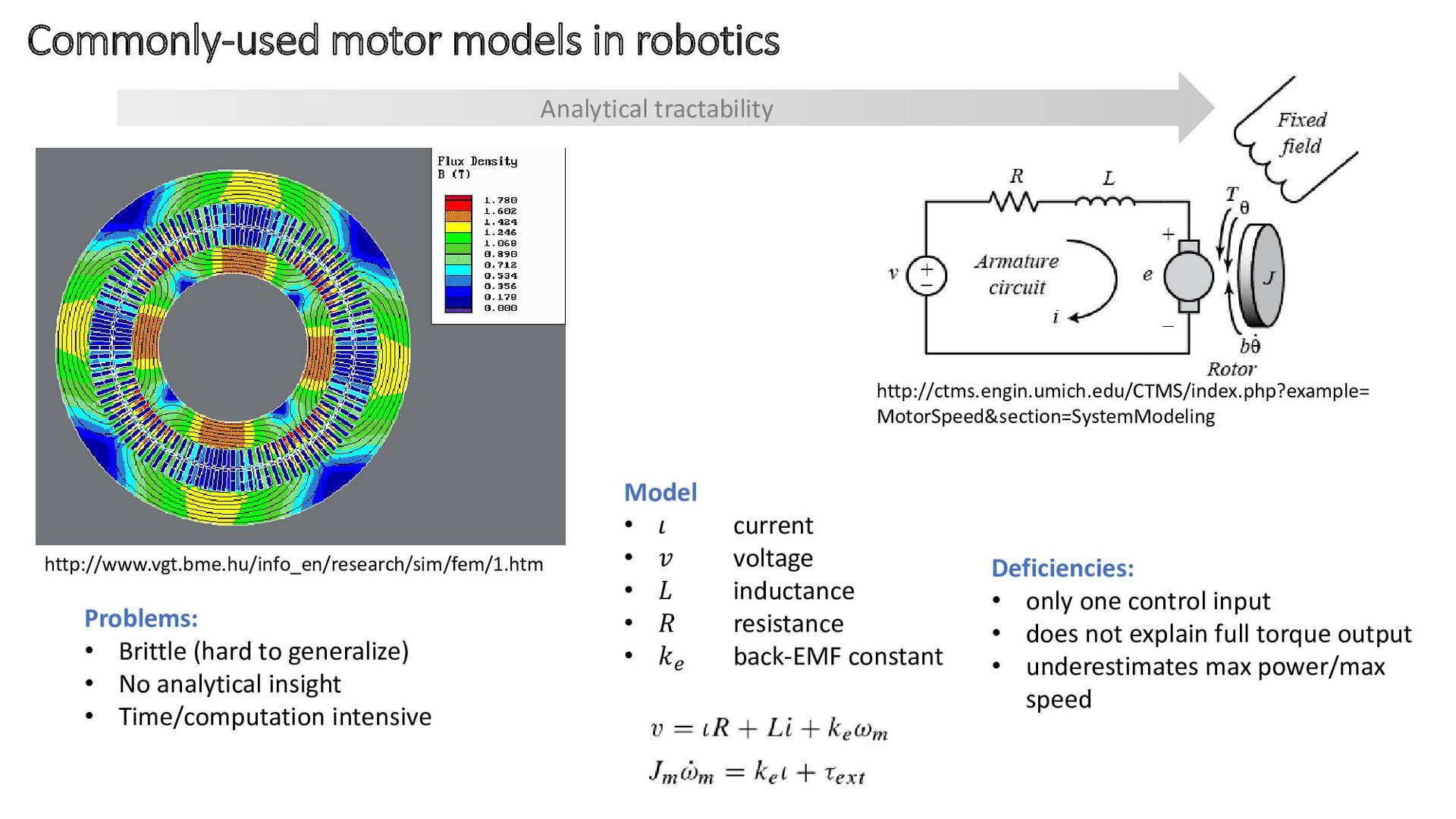
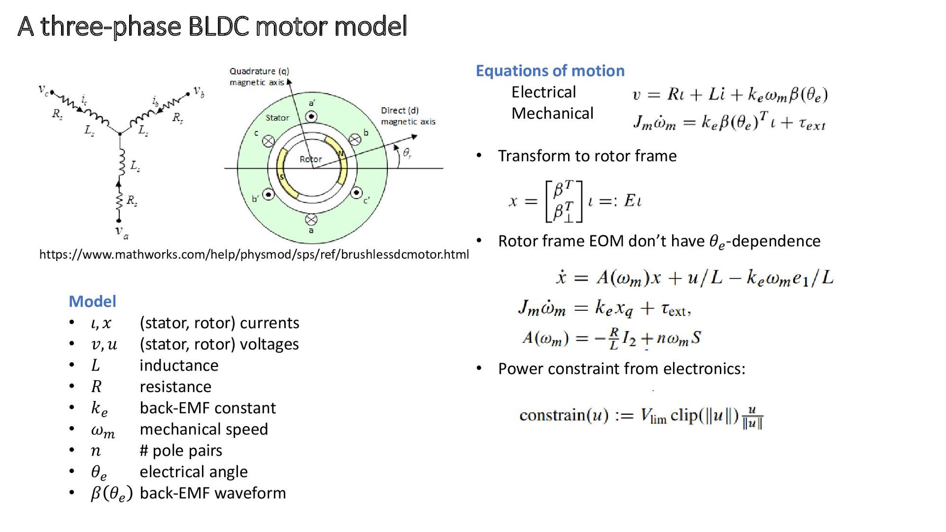
    • only one control input
    • does not explain full torque output
    • underestimates max power/max
    speed
    Model
    • 𝜄 current
    • 𝑣 voltage
    • 𝐿 inductance
    • 𝑅 resistance
    • 𝑘𝑒
    back-EMF constant
    Problems:
    • Brittle (hard to generalize)
    • No analytical insight
    • Time/computation intensive
    Analytical tractability

    View Slide

  9. Equations of motion
    Electrical
    Mechanical
    • Transform to rotor frame
    • Rotor frame EOM don’t have 𝜃𝑒
    -dependence
    • Power constraint from electronics:
    A three-phase BLDC motor model
    https://www.mathworks.com/help/physmod/sps/ref/brushlessdcmotor.html
    Model
    • 𝜄, 𝑥 (stator, rotor) currents
    • 𝑣, 𝑢 (stator, rotor) voltages
    • 𝐿 inductance
    • 𝑅 resistance
    • 𝑘𝑒
    back-EMF constant
    • 𝜔𝑚
    mechanical speed
    • 𝑛 # pole pairs
    • 𝜃𝑒
    electrical angle
    • 𝛽 𝜃𝑒
    back-EMF waveform

    View Slide

  10. Controlling the three-phase model
    Energy balance:
    Set control goal:
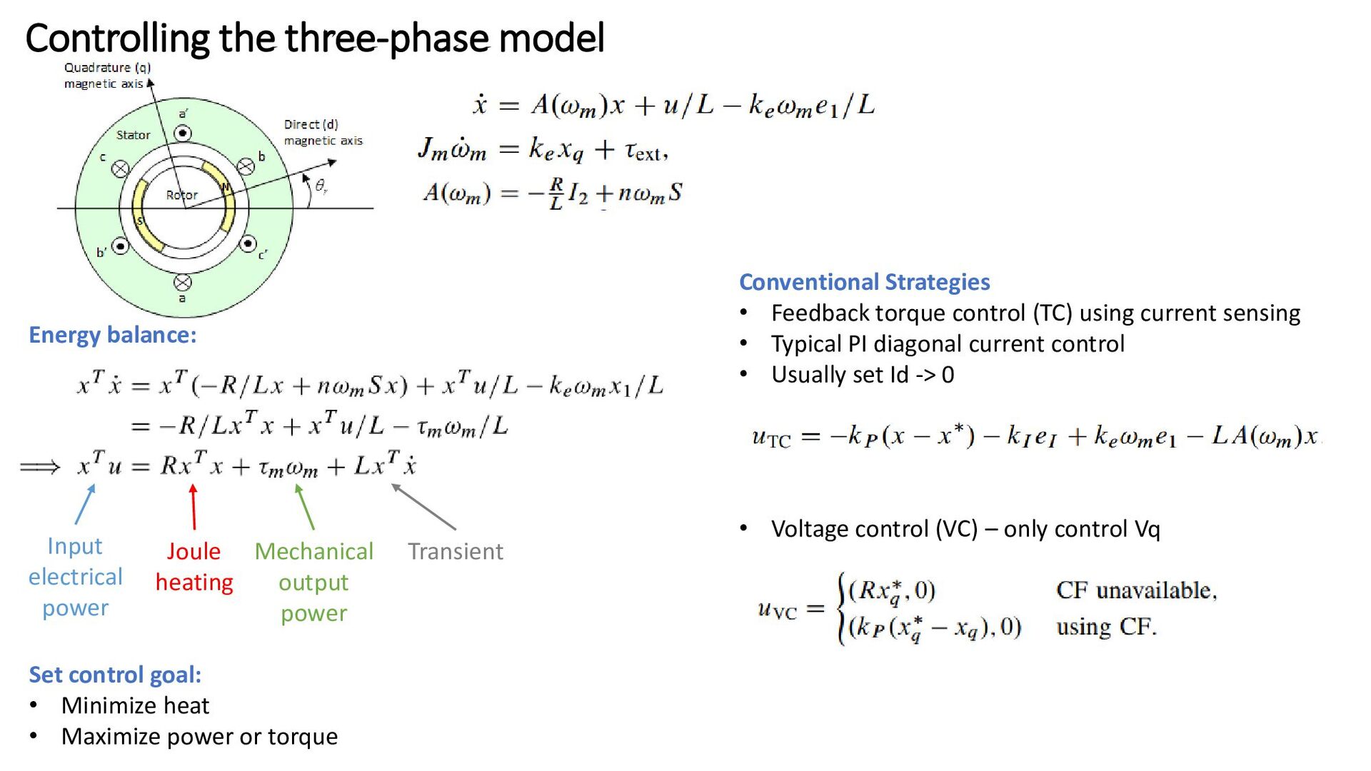
    • Minimize heat
    • Maximize power or torque
    Input
    electrical
    power
    Joule
    heating
    Mechanical
    output
    power
    Transient
    Conventional Strategies
    • Feedback torque control (TC) using current sensing
    • Typical PI diagonal current control
    • Usually set Id -> 0
    • Voltage control (VC) – only control Vq

    View Slide

  11. New “Angle Control” – couple d,q axes for task
    Peak 
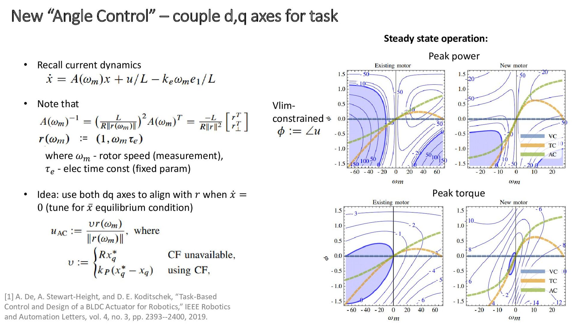
torque
    Peak power
    Vlim-
    constrained
    • Recall current dynamics
    • Note that
    where 𝜔𝑚
    - rotor speed (measurement),
    𝜏𝑒
    - elec time const (fixed param)
    • Idea: use both dq axes to align with 𝑟 when ሶ
    𝑥 =
    0 (tune for ҧ
    𝑥 equilibrium condition)
    :=
    Steady state operation:
    [1] A. De, A. Stewart-Height, and D. E. Koditschek, “Task-Based
    Control and Design of a BLDC Actuator for Robotics,” IEEE Robotics
    and Automation Letters, vol. 4, no. 3, pp. 2393--2400, 2019.

    View Slide

  12. AC disadvantage and variation with motor design
    Disadvantage: heat production
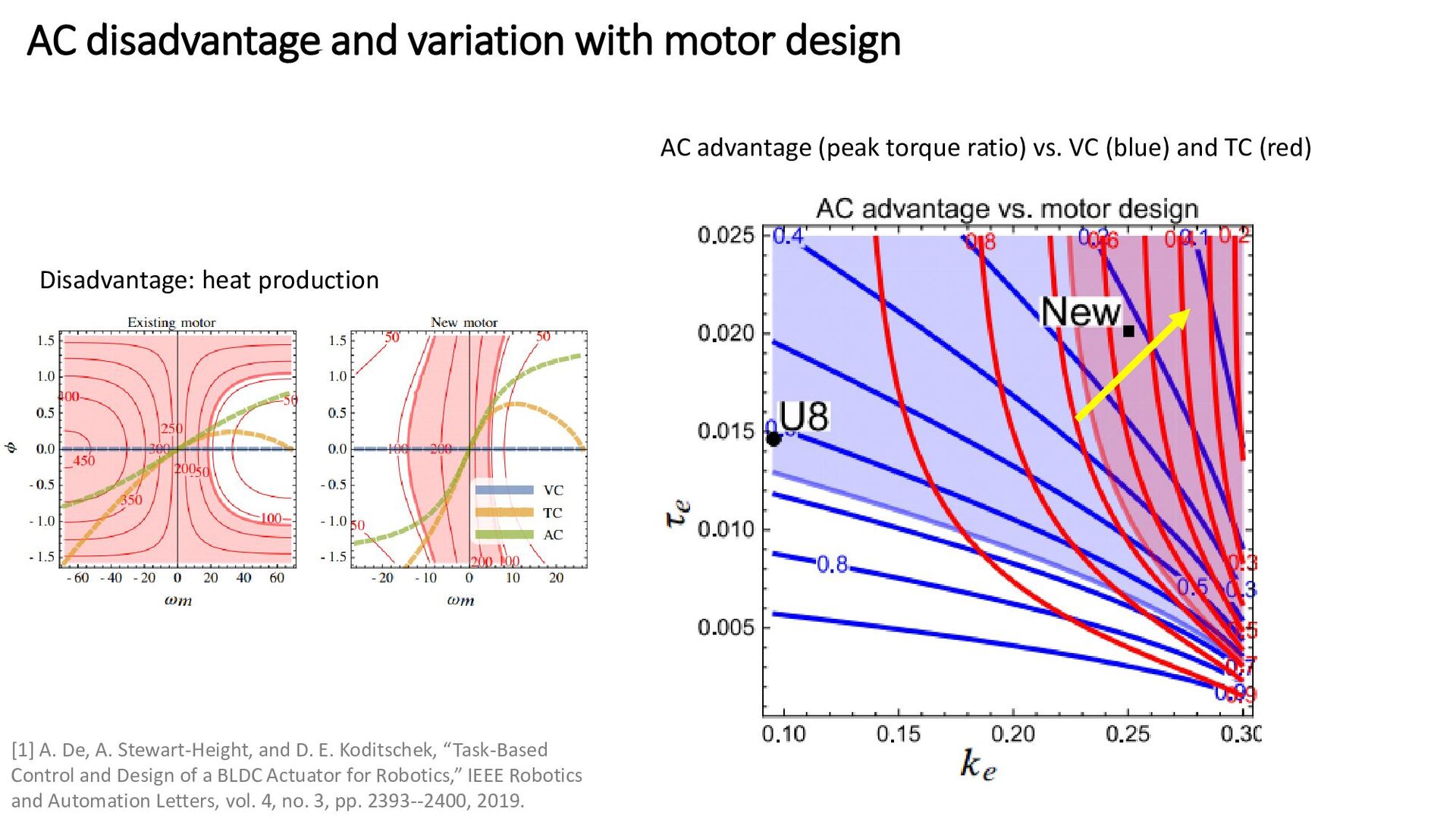
    AC advantage (peak torque ratio) vs. VC (blue) and TC (red)
    [1] A. De, A. Stewart-Height, and D. E. Koditschek, “Task-Based
    Control and Design of a BLDC Actuator for Robotics,” IEEE Robotics
    and Automation Letters, vol. 4, no. 3, pp. 2393--2400, 2019.

    View Slide

  13. Making it relevant to robotics
    1DOF experimental setup
    • “Inverted 
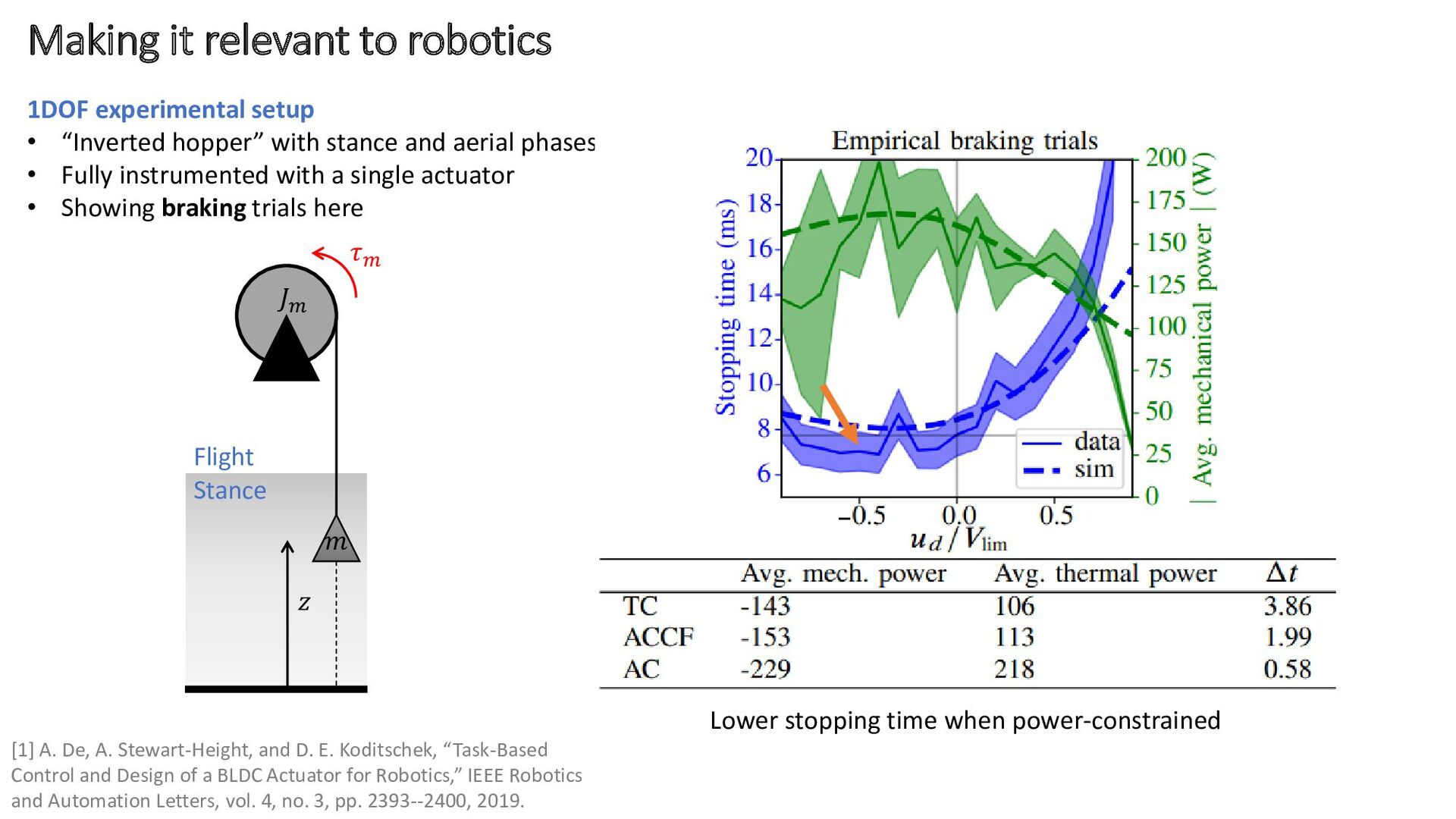
hopper” with stance and aerial phases
    • Fully instrumented with a single actuator
    • Showing braking trials here
    𝑚
    𝐽𝑚
    𝜏𝑚
    𝑧
    Flight
    Stance
    Lower stopping time when power-constrained
    [1] A. De, A. Stewart-Height, and D. E. Koditschek, “Task-Based
    Control and Design of a BLDC Actuator for Robotics,” IEEE Robotics
    and Automation Letters, vol. 4, no. 3, pp. 2393--2400, 2019.

    View Slide

  14. Summary
    • Task-based control can help get closer to fundamental limits
    • Use task to inform control strategy – rethink interface to motor controllers
    • Co-design

    View Slide