and independent - Established in 2009 - Based in Zurich and Lausanne - Portfolio of 120+ national and international brands - Full coverage of digital performance path - Sparring partner for ambitious organizations - Own software development team Webrepublic
Rust - Bought a Raspberry Pi the day it became available - Founded a Hackerspace in Rapperswil in 2013 (coredump.ch) - NOT a hardware or electronics expert! =) Twitter: @dbrgn Blog: blog.dbrgn.ch Me
as possible. - Target audience: Python developers (maybe of the webdev flavor) that have no or little experience with hardware. - Correct me if something is wrong, but... - ...simplifications are being used on purpose. This isn’t a lecture. ETA: 60–90 minutes About this talk
control hardware - Realtime performance / exact timing is often important - Deterministic runtimes: Knowing how long a CPU cycle takes Controlling Hardware with Code
- The Linux kernel can be configured to guarantee specific response times - The Raspbian kernel is not realtime - (I won’t get into the details of what defines “realtime” =)) Why Linux?
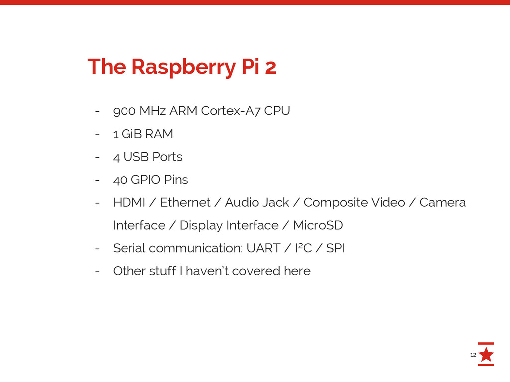
RAM - 4 USB Ports - 40 GPIO Pins - HDMI / Ethernet / Audio Jack / Composite Video / Camera Interface / Display Interface / MicroSD - Serial communication: UART / I²C / SPI - Other stuff I haven’t covered here The Raspberry Pi 2
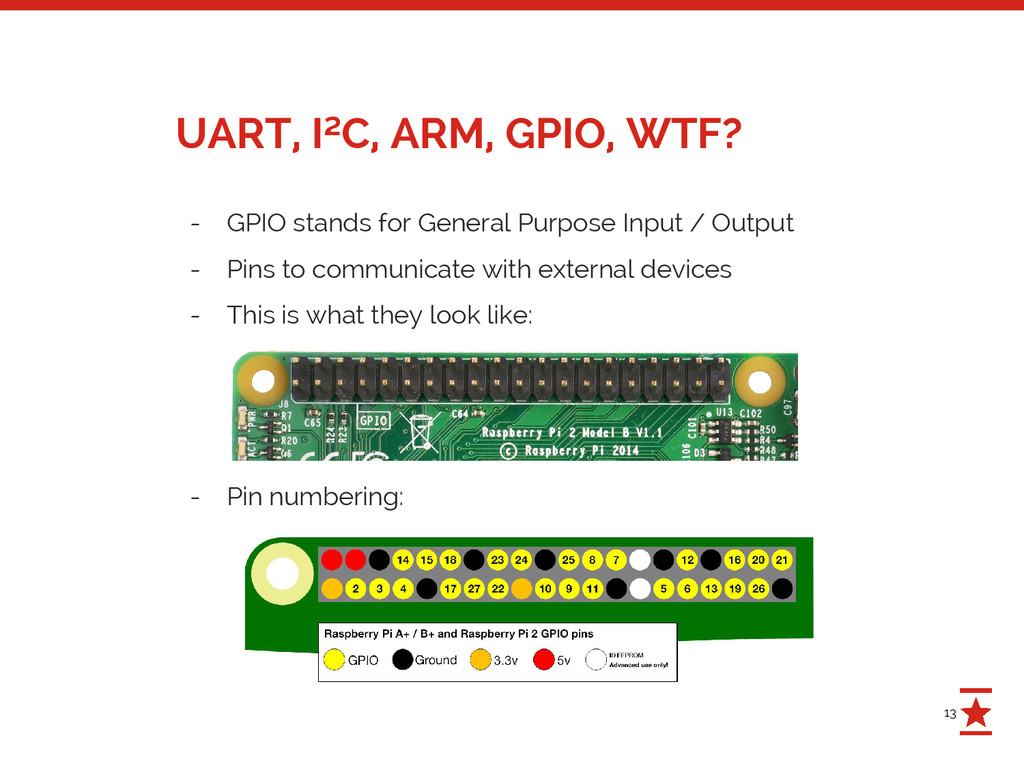
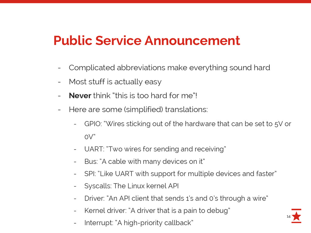
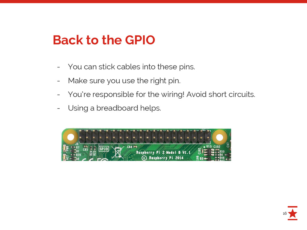
stuff is actually easy - Never think “this is too hard for me”! - Here are some (simplified) translations: - GPIO: “Wires sticking out of the hardware that can be set to 5V or 0V” - UART: “Two wires for sending and receiving” - Bus: “A cable with many devices on it” - SPI: “Like UART with support for multiple devices and faster” - Syscalls: The Linux kernel API - Driver: “An API client that sends 1’s and 0’s through a wire” - Kernel driver: “A driver that is a pain to debug” - Interrupt: “A high-priority callback” Public Service Announcement
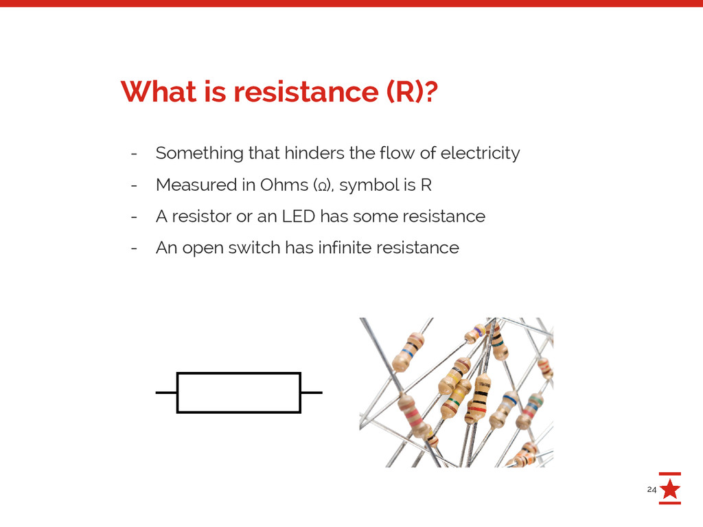
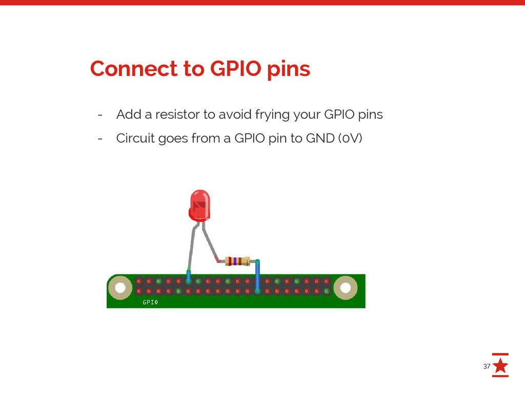
This means that you connect a voltage source (e.g. the 5V pin) with the ground pin without having anything in between that uses some of the current. - The “something in between” could be a resistor or a LED - Don’t do it! https://www.youtube.com/watch?v=PqyUtQv1WoQ What is a “short” or “shorting”?
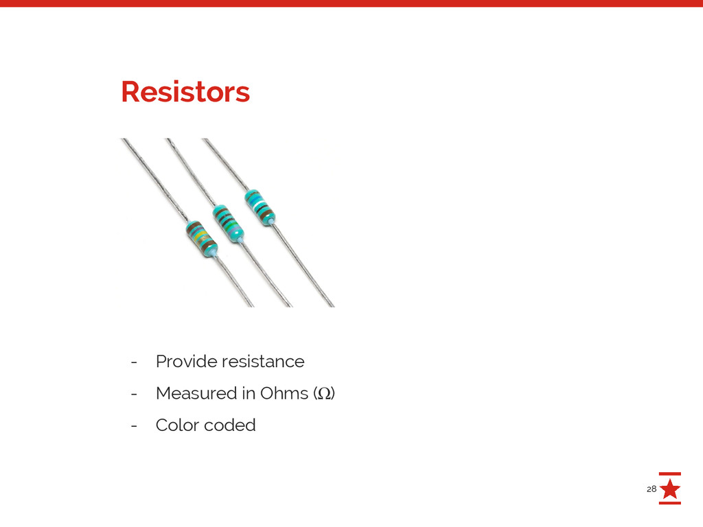
input- or output-pins - They use 3.3V internally, so don’t feed them 5V! - Maximum current draw per GPIO pin is 16 mA. - Maximum current draw for all GPIO pins is 50 mA. http://elinux.org/RPi_Low-level_peripherals http://raspberrypi.stackexchange.com/a/9299/6793 Important facts about the GPIO pins - What is a “mA”?
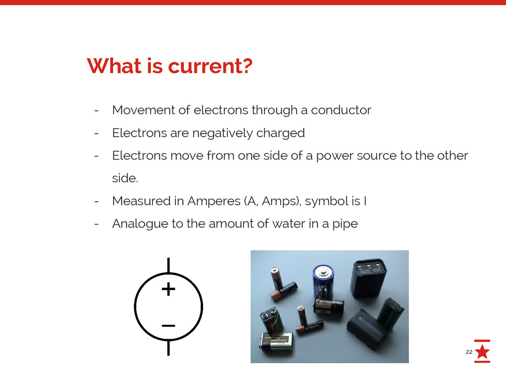
are negatively charged - Electrons move from one side of a power source to the other side. - Measured in Amperes (A, Amps), symbol is I - Analogue to the amount of water in a pipe What is current?
to the pressure in a pipe - Measured in Volts (V, Voltage), symbol is U - An AA battery has 1.3–1.5 V - The Swiss electricity grid uses ~230V What is voltage?
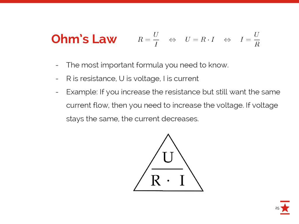
- R is resistance, U is voltage, I is current - Example: If you increase the resistance but still want the same current flow, then you need to increase the voltage. If voltage stays the same, the current decreases. Ohm’s Law
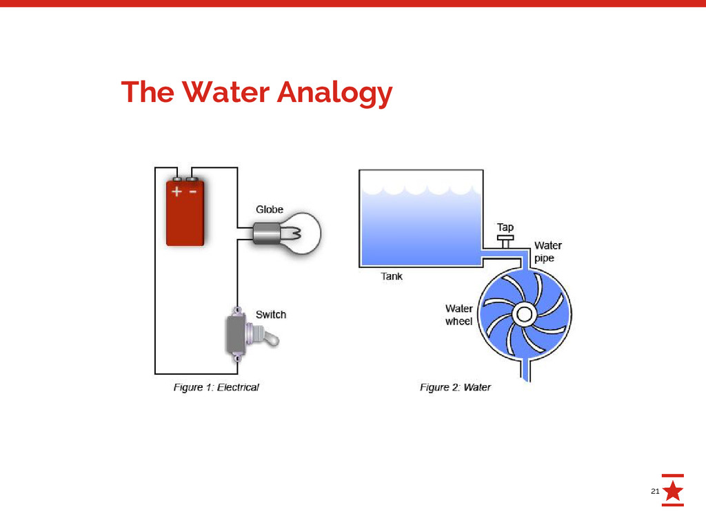
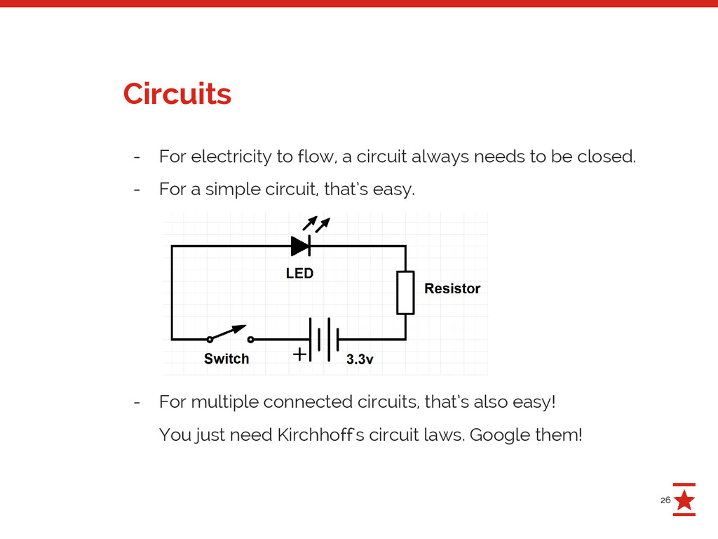
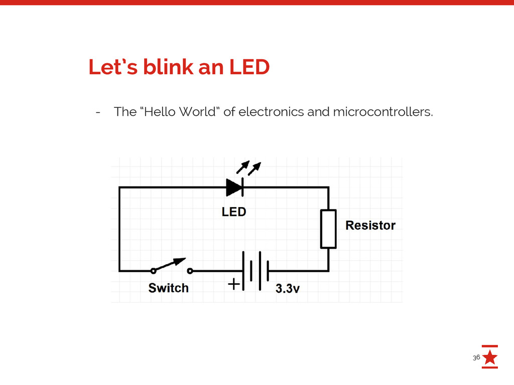
to be closed. - For a simple circuit, that’s easy. - For multiple connected circuits, that’s also easy! You just need Kirchhoff's circuit laws. Google them! Circuits
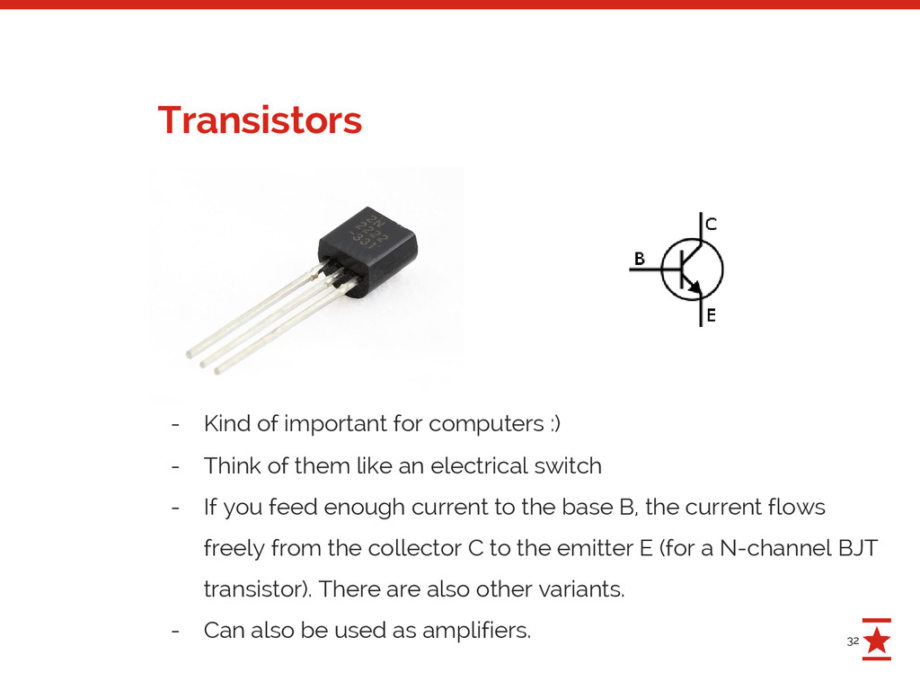
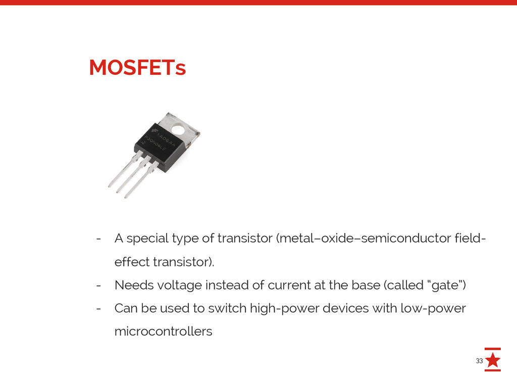
Think of them like an electrical switch - If you feed enough current to the base B, the current flows freely from the collector C to the emitter E (for a N-channel BJT transistor). There are also other variants. - Can also be used as amplifiers.
effect transistor). - Needs voltage instead of current at the base (called “gate”) - Can be used to switch high-power devices with low-power microcontrollers
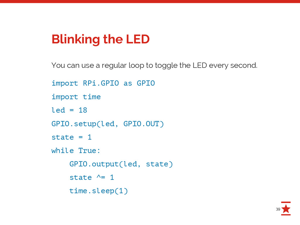
LED every second. import RPi.GPIO as GPIO import time led = 18 GPIO.setup(led, GPIO.OUT) state = 1 while True: GPIO.output(led, state) state ^= 1 time.sleep(1) Blinking the LED
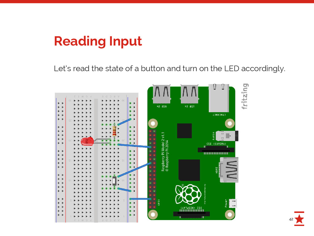
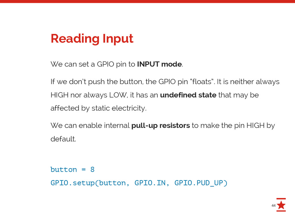
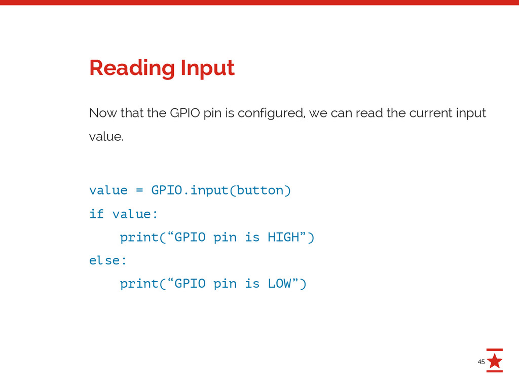
If we don’t push the button, the GPIO pin “floats”. It is neither always HIGH nor always LOW, it has an undefined state that may be affected by static electricity. We can enable internal pull-up resistors to make the pin HIGH by default. button = 8 GPIO.setup(button, GPIO.IN, GPIO.PUD_UP) Reading Input
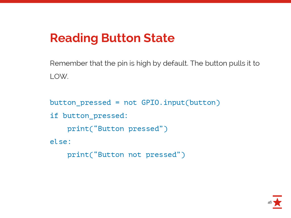
button pulls it to LOW. button_pressed = not GPIO.input(button) if button_pressed: print(“Button pressed”) else: print(“Button not pressed”) Reading Button State
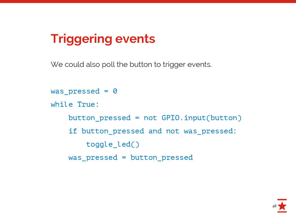
was_pressed = 0 while True: button_pressed = not GPIO.input(button) if button_pressed and not was_pressed: toggle_led() was_pressed = button_pressed Triggering events
example, our CPU load will be very high. - If you’re a webdev you know that polling sucks. - Instead, you want to wait for an event or register a callback. - Turns out, we can! In hardware-land, events are called interrupts. Polling?
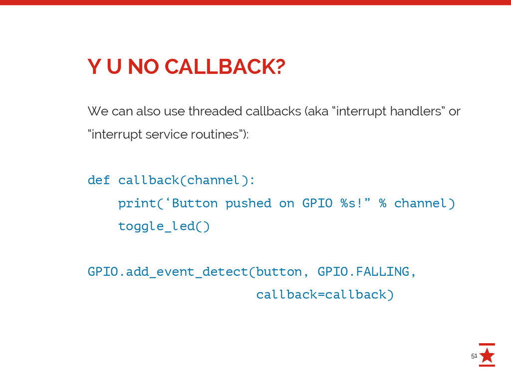
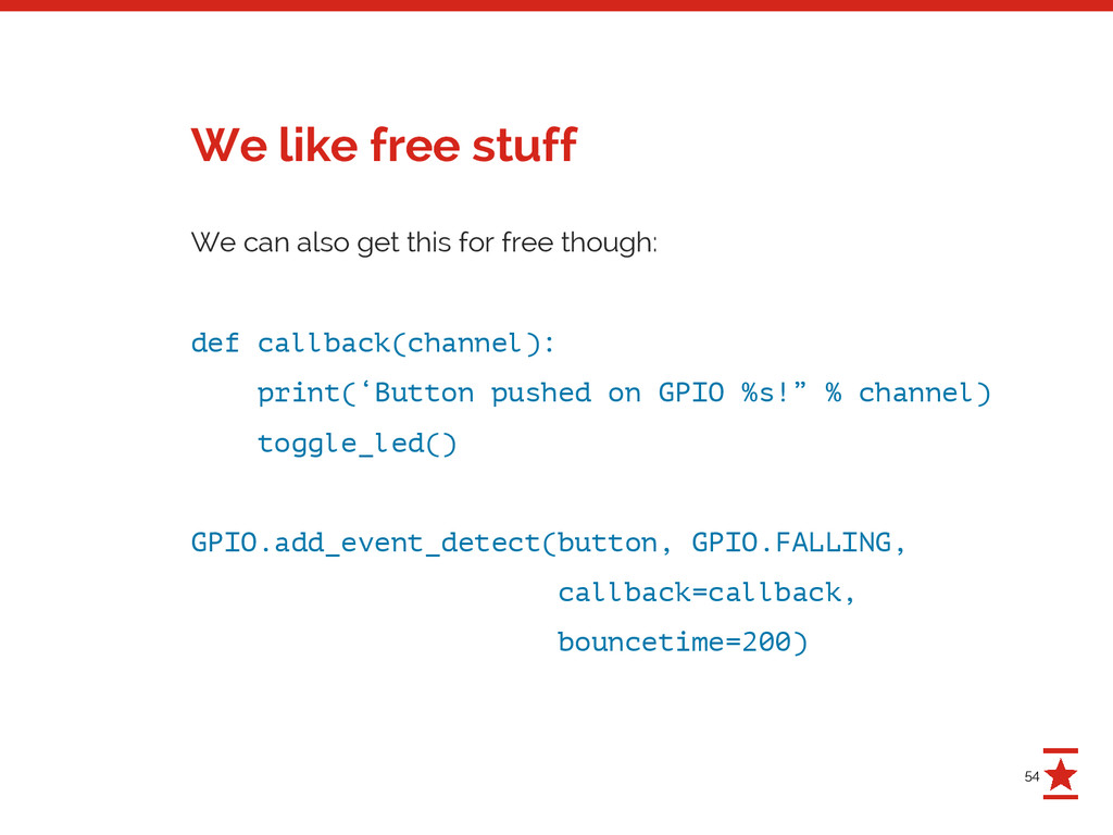
or “interrupt service routines”): def callback(channel): print(‘Button pushed on GPIO %s!” % channel) toggle_led() GPIO.add_event_detect(button, GPIO.FALLING, callback=callback) Y U NO CALLBACK?
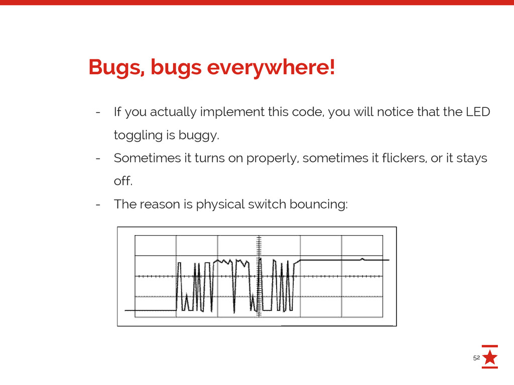
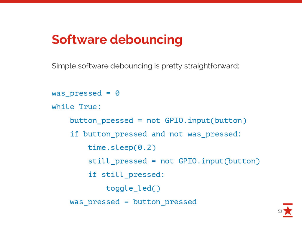
notice that the LED toggling is buggy. - Sometimes it turns on properly, sometimes it flickers, or it stays off. - The reason is physical switch bouncing: Bugs, bugs everywhere!
while True: button_pressed = not GPIO.input(button) if button_pressed and not was_pressed: time.sleep(0.2) still_pressed = not GPIO.input(button) if still_pressed: toggle_led() was_pressed = button_pressed Software debouncing
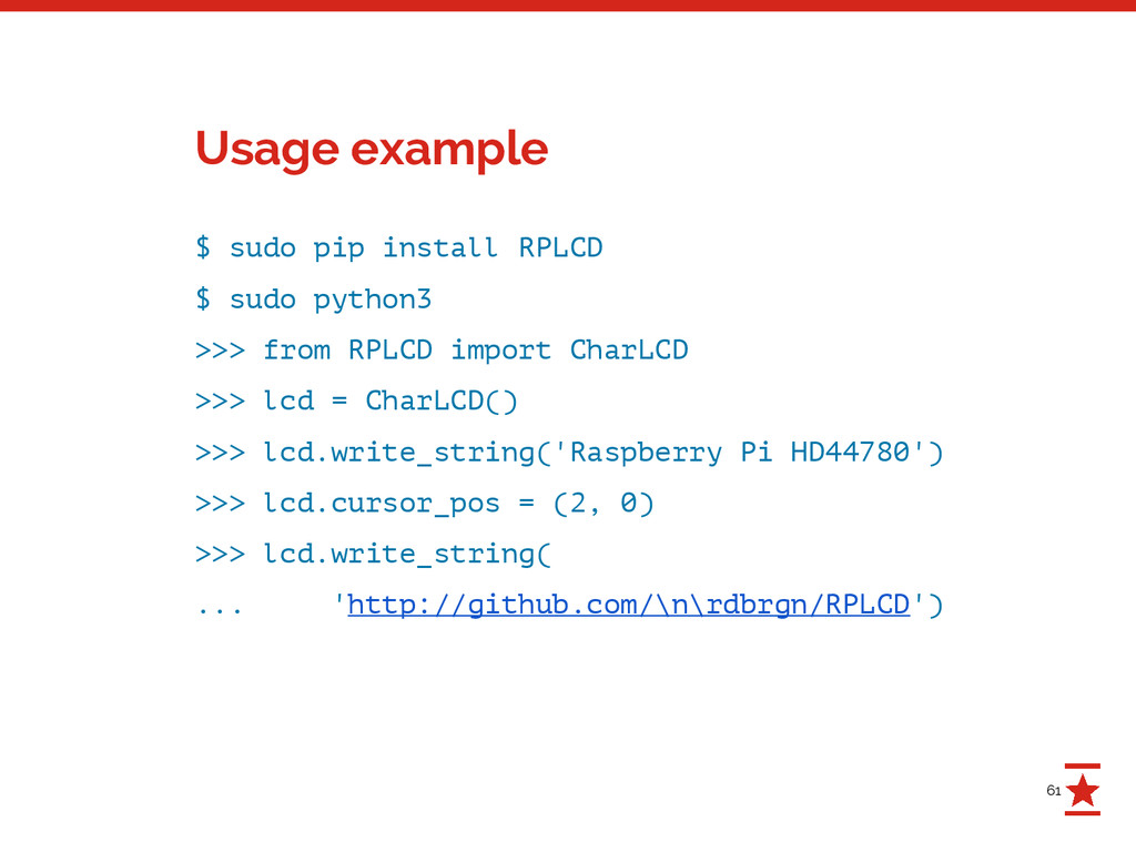
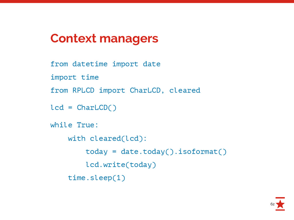
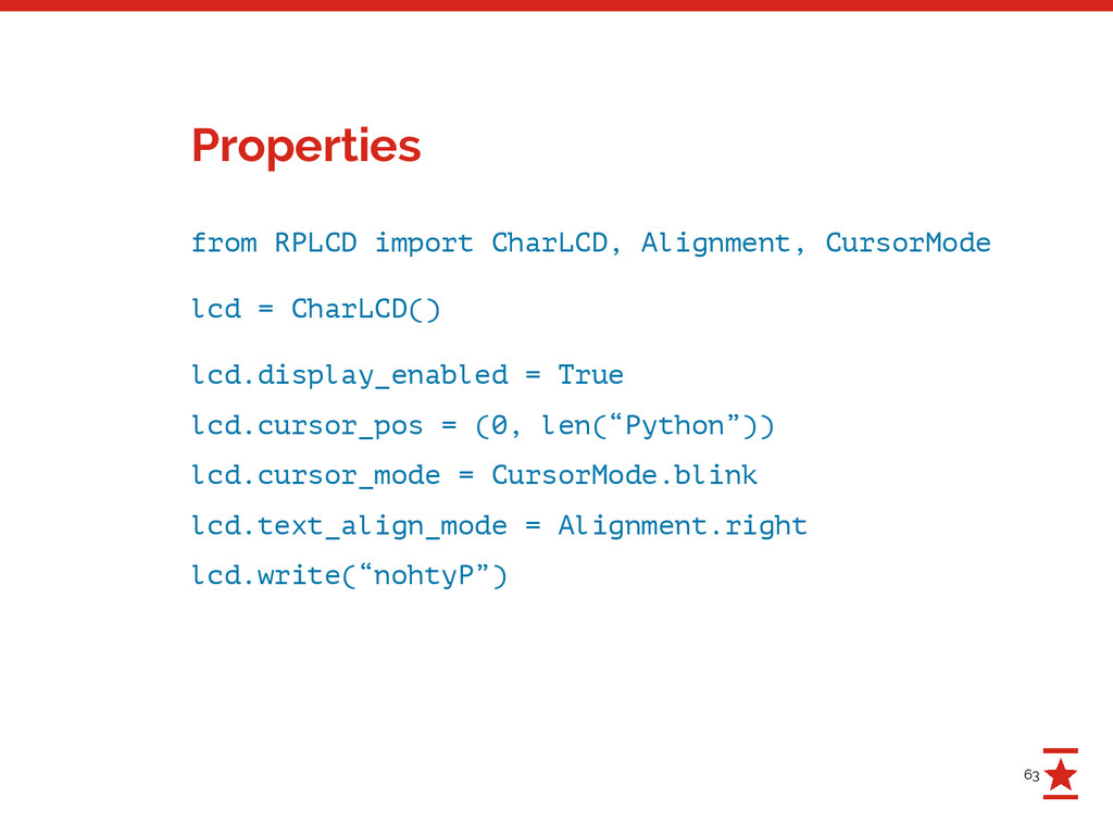
control HD44780 displays. - Idiomatic Python 2 / 3 - Properties instead of getters / setters - Simple test suite (with human interaction) - Caching: Only write characters if they changed - Support for custom characters - No external dependencies - MIT licensed https://github.com/dbrgn/RPLCD https://pypi.python.org/pypi/RPLCD/ What is RPLCD?
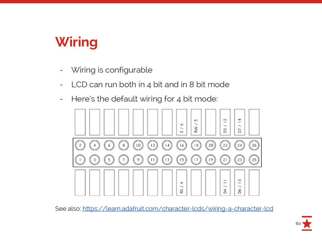
in 4 bit and in 8 bit mode - Here’s the default wiring for 4 bit mode: See also: https://learn.adafruit.com/character-lcds/wiring-a-character-lcd Wiring
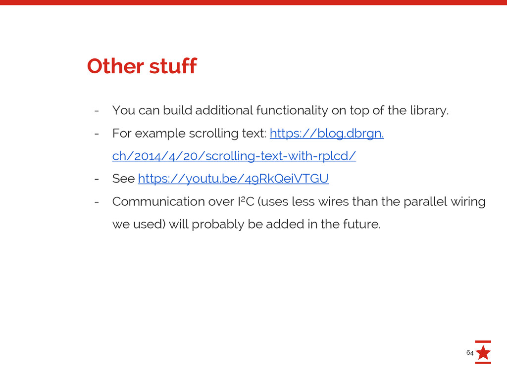
the library. - For example scrolling text: https://blog.dbrgn. ch/2014/4/20/scrolling-text-with-rplcd/ - See https://youtu.be/49RkQeiVTGU - Communication over I²C (uses less wires than the parallel wiring we used) will probably be added in the future. Other stuff
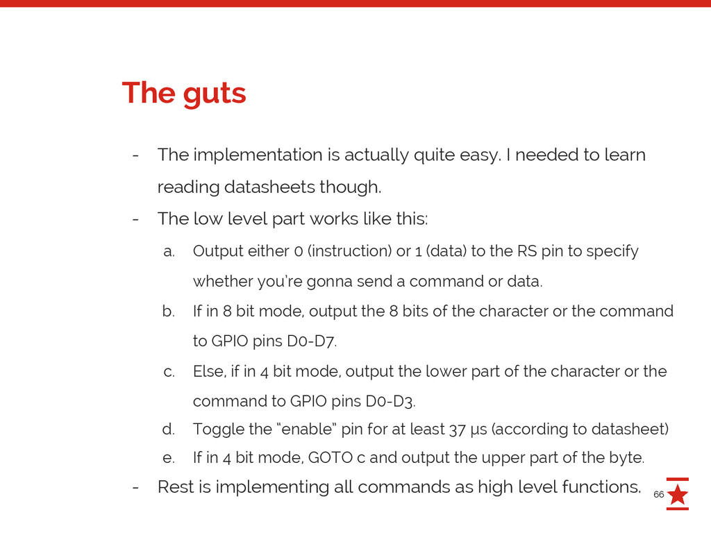
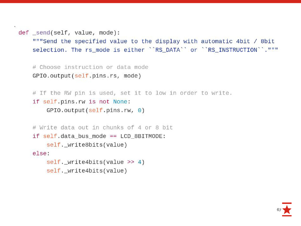
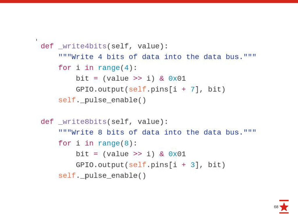
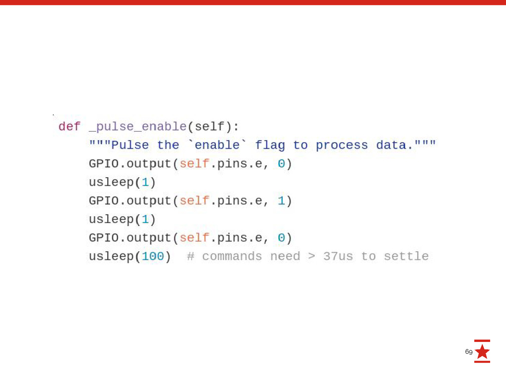
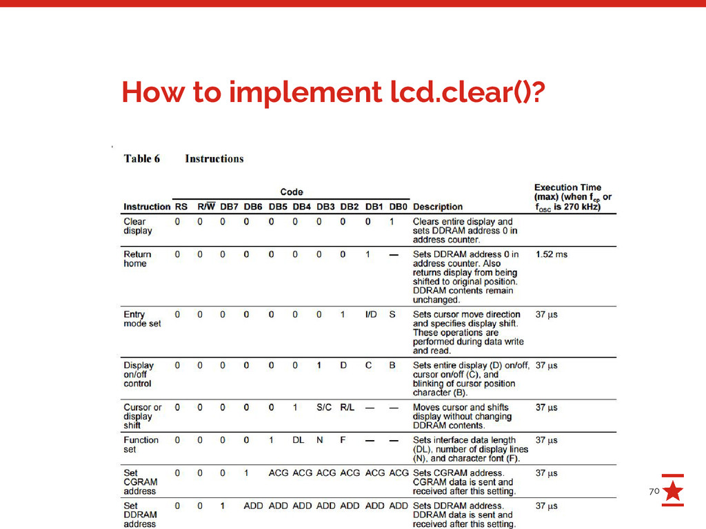
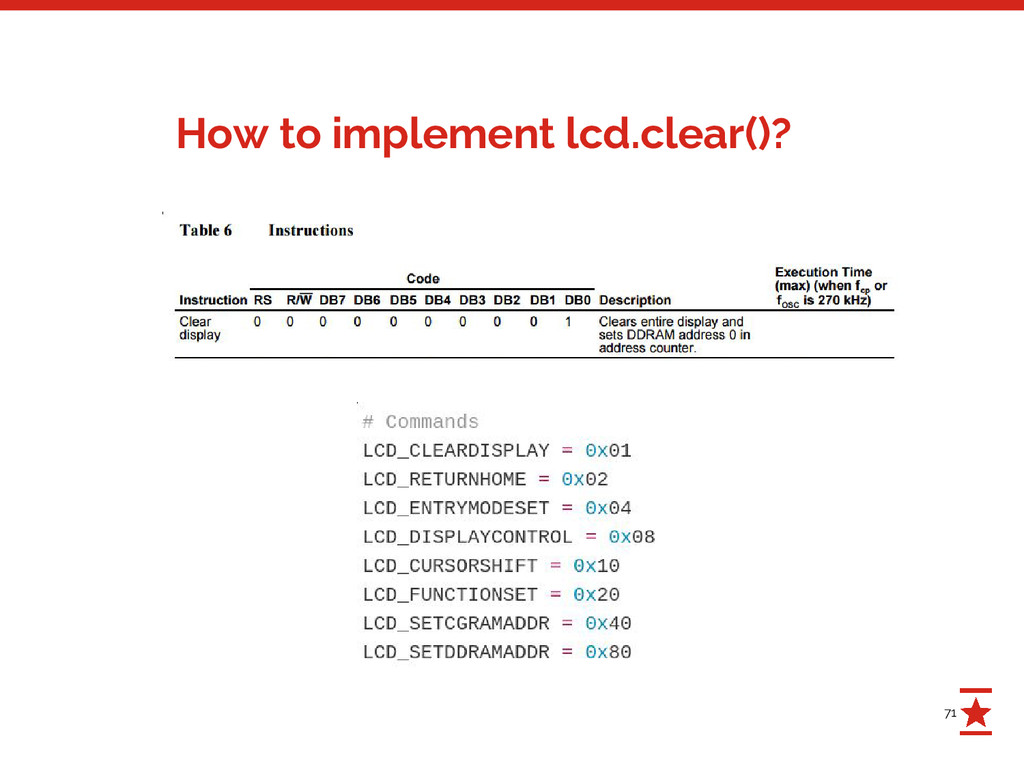
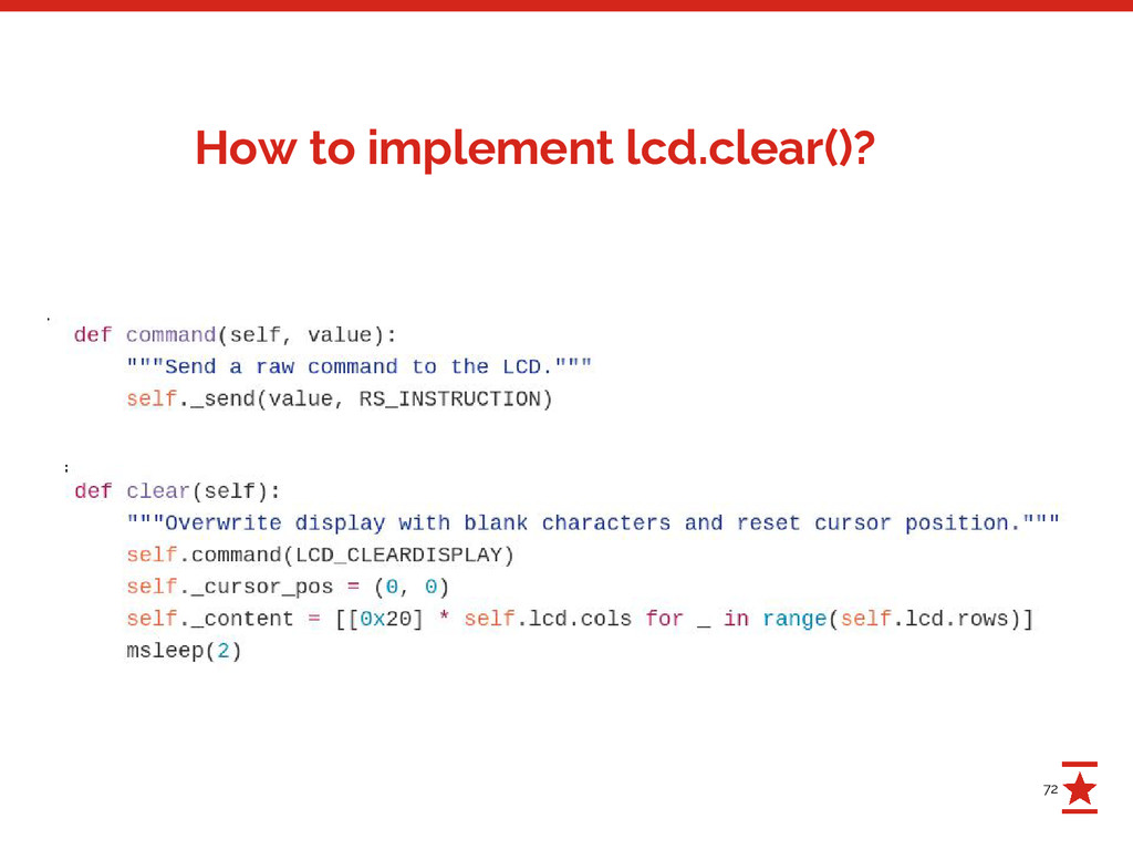
to learn reading datasheets though. - The low level part works like this: a. Output either 0 (instruction) or 1 (data) to the RS pin to specify whether you’re gonna send a command or data. b. If in 8 bit mode, output the 8 bits of the character or the command to GPIO pins D0-D7. c. Else, if in 4 bit mode, output the lower part of the character or the command to GPIO pins D0-D3. d. Toggle the “enable” pin for at least 37 µs (according to datasheet) e. If in 4 bit mode, GOTO c and output the upper part of the byte. - Rest is implementing all commands as high level functions. The guts