Upgrade to Pro — share decks privately, control downloads, hide ads and more …

Caterpillar_Cat_980G_Wheel_Loader__Prefix_2KR__Service_Repair_Manual__2KR00001_and_up_.pdf

dcfv
May 20, 2024
3

 Caterpillar_Cat_980G_Wheel_Loader__Prefix_2KR__Service_Repair_Manual__2KR00001_and_up_.pdf

dcfv

May 20, 2024
Tweet

More Decks by dcfv

Transcript

  1. Shutdown SIS Previous Screen Product: WHEEL LOADER Model: 980G WHEEL

    LOADER 2KR Configuration: 980G Wheel Loader 2KR00001-UP (MACHINE) POWERED BY 3406C Engine Disassembly and Assembly 980G Wheel Loader Power Train Media Number -SENR5877-07 Publication Date -01/09/2004 Date Updated -23/09/2004 i04400940 Torque Converter - Assemble - Heavy duty SMCS - 3101-016 Assembly Procedure Table 1 Required Tools Tool Part Number Part Description Qty A 138-7573 Link Bracket 3 B 8T-5096 Dial Indicator Test Group 1 5P-2390 Gauge Tool Group 1 C 1P-0520 Driver Group 1 Note: Cleanliness is an important factor. Before assembly, all parts should be thoroughly cleaned in cleaning fluid. Allow the parts to air dry. Wiping cloths or rags should not be used to dry parts. Lint may be deposited on the parts which may cause later trouble. Inspect all parts. If any parts are worn or damaged, use new parts for replacement. Note: Apply oil to all of the bearings before assembly.
  2. Illustration 1 g00504278 1. Use Tooling (C) to install sleeve

    bearing (59) in cover assembly (57). Sleeve bearing (59) must be even with the outside surface of cover assembly (57). Illustration 2 g00504279 2. Install cover assembly (57) to rotating housing (39). Illustration 3 g00503564 3. Install ring seal (58) to rotating housing (39).
  3. 4. Install eight bolts (56) and the washers. Tighten the

    bolts to a torque of 30 ± 5 N·m (22 ± 4 lb ft). Illustration 4 g00504307 5. Install thrust bearing race (54), thrust bearing (55), and thrust bearing race (54) to cover assembly (57). Illustration 5 g00504312 6. Install retaining ring (53) in turbine hub (51). Illustration 6 g00504313
  4. 7. Install converter turbine (50) on turbine hub (51). Illustration

    7 g00504315 8. Install twenty bolts (52). Tighten the bolts to a torque of 50 ± 7 N·m (37 ± 5 lb ft). Illustration 8 g00504382 9. Install turbine hub (51) and converter turbine (50) as a unit to rotating housing (39). Illustration 9 g00503538 10. Install two thrust bearing races (49) and the bearing to the hub.
  5. Illustration 10 g00504436 11. Use Tooling (C) to install sleeve

    bearing (48) to carrier assembly (44). Bearing sleeve (48) must be even with the counterbore of carrier assembly (44). Illustration 11 g00504882 12. Install retainer ring (47) in stator (46). Illustration 12 g00504931 13. Position carrier assembly (44) on a wood block.
  6. https://www.aservicemanualpdf.com/ My Dear Friend! Thank you very much for visiting.

    Full manual if required, please enter the following URL into your browser. https://www.aservicemanualpdf.com/
  7. 14. Use proper equipment to handle stator (46). Heat stator

    (46) to a maximum temperature of 121°C (250°F) for one hour. 15. Install stator (46) on carrier assembly (44). Illustration 13 g00504935 16. Install snap ring (45) in stator (46). Illustration 14 g00505049 17. Install stator (46) and carrier assembly (44) in rotating housing (39). Illustration 15 g00503352
  8. 18. Install two thrust bearing races (43) and the thrust

    bearing to the carrier assembly. Illustration 16 g00503351 19. Position impeller hub (42) on a wood block. 20. Install converter impeller (41) on impeller hub (42). Illustration 17 g00503350 21. Install drive flange (38) on converter impeller (41). Illustration 18 g00503348
  9. 22. Install twelve bolts (40). Tighten the bolts to a

    torque of 80 ± 10 N·m (60 ± 7 lb ft). Illustration 19 g00503345 23. Install drive flange (38) on rotating housing (39). The weight of drive flange (38) is 23 kg (51 lb). 24. Install 36 bolts (37) and the washers. Tighten the bolts to a torque of 30 ± 5 N·m (22 ± 4 lb ft). Illustration 20 g00505183 25. Install retaining ring (36) in the groove of drive gear (35).
  10. Illustration 21 g00505224 26. Use the proper equipment to handle

    outer bearing race (60). Lower the temperature of outer bearing race (60). 27. Install outer bearing race (60) in drive gear (35). Make sure that outer bearing race (60) makes contact with retaining ring (36). Illustration 22 g00505319 28. Install drive gear (35) on drive flange (38). Illustration 23 g00505349 29. Install twelve bolts (34) and the washers. Tighten the bolts to a torque of 50 ± 7 N·m (37 ± 5 lb ft).
  11. Illustration 24 g00505352 30. Use the proper equipment to handle

    inner bearing (33). Heat inner bearing (33) to a maximum temperature of 135°C (275°F). Install inner bearing (33) on bearing carrier (28). Illustration 25 g00505358 31. Install retaining ring (32) in the groove of bearing carrier (28). Illustration 26 g00505359 32. Use the proper equipment to handle ring carrier (31). Heat ring carrier (31) to a maximum temperature of 135°C (275°F). Install ring carrier (31) on bearing carrier (28).
  12. Illustration 27 g00505387 33. Install seal ring (30) on ring

    carrier (31). 34. Install O-ring seal (29) on bearing carrier (28). Illustration 28 g00505395 35. Install bearing carrier (28) in drive flange (38). Illustration 29 g00505423 36. Install retaining ring (27) in carrier assembly (44) in order to hold bearing carrier (28) in place.
  13. Illustration 30 g00503312 37. Install two studs (26) in torque

    converter housing assembly (2). Tighten the studs to a torque of 100 ± 15 N·m (74 ± 11 lb ft). Illustration 31 g00505444 38. Install retaining ring (24) in the groove of idler gear (15). Illustration 32 g00505465 39. Use the proper equipment to handle bearing cup (25). Lower the temperature of bearing cup (25). Install bearing cup (25) in idler gear (15).
  14. Illustration 33 g00505470 40. Flip idler gear (15) to the

    opposite side. Install bearing cup spacer (23) in idler gear (15). The notch in bearing cup spacer (23) must be aligned with retaining ring (24). Illustration 34 g00505479 41. Use the proper equipment to handle bearing cup (22). Lower the temperature of bearing cup (22). Install bearing cup (22) in idler gear (15). Illustration 35 g00505480 42. Install bearing cone (21), bearing cone spacer (20) and bearing cone (19) in idler gear (15).
  15. Illustration 36 g00505482 43. Apply clean hydraulic oil on O-ring

    seal (17). Install O-ring seal (17) on shaft assembly (18). Illustration 37 g00505508 44. Install 1/2" - 13 NC guide pin (61) in shaft assembly (18). 45. Hold transfer gear (15) in position in torque converter housing assembly (2). Install shaft assembly (18). 46. Remove guide pin (61) from shaft assembly (18). Illustration 38 g00505517
  16. 47. Install bolt (14) that holds shaft assembly (18) in

    place in torque converter housing assembly (2). Tighten the bolt to a torque of 120 ± 20 N·m (90 ± 15 lb ft). Illustration 39 g00505572 48. Use the proper equipment to handle bearing cones (12). Heat bearing cones to a maximum temperature of 135°C (275°F). Install a bearing cone (12) on each side of pump drive gear (11). Illustration 40 g00505585 49. Use the proper equipment to handle bearing cup (13). Lower the temperature of bearing cup (13). Install bearing cup (13) in torque converter housing assembly (2).
  17. Illustration 41 g00505591 50. Install pump drive gear (11) in

    torque converter housing assembly (2). Illustration 42 g00505594 51. Use the proper equipment to handle bearing cup (8). Lower the temperature of bearing cup (8). Install bearing cup (8) in pump adapter (6). Illustration 43 g00505623 52. Install shims (9) on pump adapter (6). 53. Apply clean hydraulic oil on O-ring seal (10). Install O-ring seal (10) on pump adapter (6).
  18. Illustration 44 g00505666 54. Install two 3/8" - 16 NC

    guide pins (62) in torque converter housing assembly (2). 55. Install pump adapter (6) on torque converter housing assembly (2). Illustration 45 g00505669 56. Install thirteen bolts (5) and the washers. 57. Use Tooling (B) to check bearing end play. The bearing end play must be 0.15 ± 0.05 mm (.006 ± .002 inch). Add or remove shims in order to get the correct bearing end play. Note: If end play is less than 0.10 mm (.004 inch) add additional shims. If end play is greater than 0.20 mm (.008 inch) remove shims. Illustration 46 g00505670 58. Apply clean hydraulic oil on O-ring seal (4). Install O-ring seal (4) on torque converter housing assembly (2).
  19. Illustration 47 g01022823 59. Install two 1/2" - 13 NC

    guide pins (63) in the carrier assembly. 60. Install Tooling (A) to torque converter housing assembly (2), as shown. Attach a hoist and suitable lifting chains to Tooling (A). Use the hoist to carefully install torque converter housing assembly (2) on the torque converter. Illustration 48 g00503225 61. Install eight bolts (1) and the washers to torque converter housing assembly (2). Tighten the bolts to a torque of 120 ± 20 N·m (90 ± 15 lb ft). End By: a. Connect the torque converter to the transmission and to the output transfer gears. Refer to Disassembly and Assembly, "Torque Converter to Transmission, Output Transfer Gears - Connect" for the machine that is being serviced. Copyright 1993 - 2022 Caterpillar Inc. All Rights Reserved. Private Network For SIS Licensees. Fri Feb 18 19:17:03 UTC+0800 2022
  20. Shutdown SIS Previous Screen Product: WHEEL LOADER Model: 980G WHEEL

    LOADER 2KR Configuration: 980G Wheel Loader 2KR00001-UP (MACHINE) POWERED BY 3406C Engine Disassembly and Assembly 980G Wheel Loader Power Train Media Number -SENR5877-07 Publication Date -01/09/2004 Date Updated -23/09/2004 i00990349 Torque Converter to Transmission, Output Transfer Gears - Connect SMCS - 3003-077 Connection Procedure Table 1 Required Tools Tool Part Number Part Description Qty A 1U-9759 Stand 1 B 138-7574 Link Bracket 4 C 138-7574 Link Bracket 1 Illustration 1 g00506075
  21. 1. Use a hoist and suitable lifting chains to carefully

    position the transmission and the output transfer gears on Tooling (A) and on wood blocks, as shown. The weight of the transmission and the transfer gears as a unit is 1160 kg (2560 lb). Note: Check the condition of all O-ring seals and of all parts. If any components are worn or damaged, use new parts for replacement. Illustration 2 g00504723 2. Check output shaft (20) for wear or damage. If necessary, replace output shaft (20) . Illustration 3 g00502950 3. Install output shaft (20) in torque converter (3) . 4. Install O-ring seal (19) on torque converter (3). Apply clean power train oil on O-ring seal (19) .
  22. Illustration 4 g00502897 5. Use a hoist and suitable lifting

    chains to carefully install torque converter (3) to transmission (14). The weight of torque converter (3) is 240 kg (530 lb). Use the output shaft to align torque converter (3) with transmission (14) . Illustration 5 g00502895 6. Install two brackets (17), eleven bolts (18) and the washers to torque converter (3) and transmission (14) .
  23. Illustration 6 g00502885 7. Remove Tooling (C) from torque converter

    (3) . Illustration 7 g00502872 8. Install manifold (16) and five bolts (15) to torque converter (3) and transmission (14) . Illustration 8 g00502652 9. Remove Tooling (B) from the transmission and the transfer gears.
  24. Illustration 9 g00502643 10. Use a hoist and a suitable

    lifting sling to carefully install steering pump (7), transmission pump (8) and brake pump (9) to the torque converter. The weight of the three pumps as a unit is 80 kg (176 lb). 11. Install three bolts (13) and the washers. Illustration 10 g00502627 12. Install hose assembly (12) and bolt (11) to torque converter (3) .
  25. Illustration 11 g00502597 13. Install two tube assemblies (10) as

    a unit to steering pump (7) and brake pump (9) . 14. Install tube assembly (6) to transmission pump (8) . Illustration 12 g00502478 15. Install four bolts (5) and the washers that secure tube assembly (6) to transmission magnetic screen (4) .
  26. Illustration 13 g00502465 16. Install relief valve (2) and three

    bolts (1) on torque converter (3) . 17. Fill the transmission with oil. For the correct procedure, refer to Operation and Maintenance Manual for the machine that is being serviced. End By: Connect the engine to the torque converter, to the transmission and to the output transfer gears. Refer to Disassembly and Assembly, "Engine to Torque Converter, Transmission, Output Transfer Gears - Connect" for the machine that is being serviced. Copyright 1993 - 2022 Caterpillar Inc. All Rights Reserved. Private Network For SIS Licensees. Fri Feb 18 19:17:58 UTC+0800 2022
  27. Shutdown SIS Previous Screen Product: WHEEL LOADER Model: 980G WHEEL

    LOADER 2KR Configuration: 980G Wheel Loader 2KR00001-UP (MACHINE) POWERED BY 3406C Engine Disassembly and Assembly 980G Wheel Loader Power Train Media Number -SENR5877-07 Publication Date -01/09/2004 Date Updated -23/09/2004 i00992217 Output Transfer Gears from Transmission, Torque Converter - Separate SMCS - 3003-076 Separation Procedure Table 1 Required Tools Tool Part Number Part Description Qty A 6V-6146 Load Leveler 1 138-7574 Link Bracket 2 B 8S-7640 Stand 4 8S-7611 Tube 4 8S-7615 Pin 4 C 1U-9759 Stand 1 D 138-7574 Link Bracket 4 Start By: A. Remove the engine, the torque converter, the transmission and the output transfer gears. Refer to Disassembly and Assembly, "Engine, Torque Converter, Transmission and Output Transfer Gears - Remove" for the machine that is being serviced.
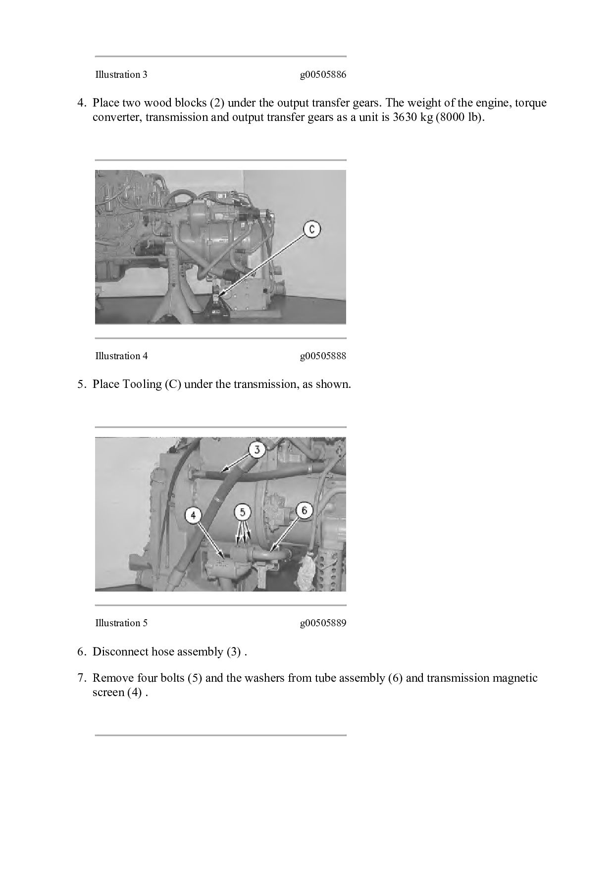
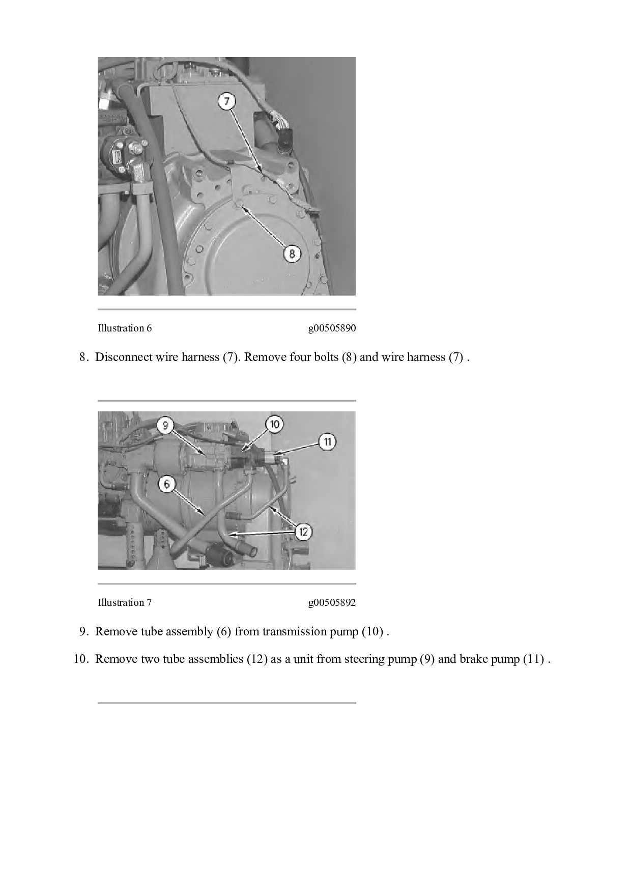
  28. Please write to us. Our email: [email protected] Please go to

    the homepage to get the full manual, or other brand PDF manuals. Home Site: aservicemanualpdf.com
  29. Thank you very much for your reading. Please Click Here.

    Then Get COMPLETE MANUAL. NO WAITING NOTE: If there is no response to click on the link above, please download the PDF document first and then click on it.
  30. Illustration 1 g00505884 1. Remove two tube assemblies (1) as

    a unit from the engine and the output transfer gears. Illustration 2 g00505885 2. Attach Tooling (A) to the engine and the output transfer gears, as shown. Attach a hoist and suitable lifting chains to Tooling (A) . 3. Use the hoist to carefully lower the engine, the torque converter, the transmission and the output transfer gears on Tooling (B), as shown.
  31. Illustration 3 g00505886 4. Place two wood blocks (2) under

    the output transfer gears. The weight of the engine, torque converter, transmission and output transfer gears as a unit is 3630 kg (8000 lb). Illustration 4 g00505888 5. Place Tooling (C) under the transmission, as shown. Illustration 5 g00505889 6. Disconnect hose assembly (3) . 7. Remove four bolts (5) and the washers from tube assembly (6) and transmission magnetic screen (4) .
  32. Illustration 6 g00505890 8. Disconnect wire harness (7). Remove four

    bolts (8) and wire harness (7) . Illustration 7 g00505892 9. Remove tube assembly (6) from transmission pump (10) . 10. Remove two tube assemblies (12) as a unit from steering pump (9) and brake pump (11) .
  33. https://www.aservicemanualpdf.com/ My Dear Friend! Thank you very much for visiting.

    Full manual if required, please enter the following URL into your browser. https://www.aservicemanualpdf.com/