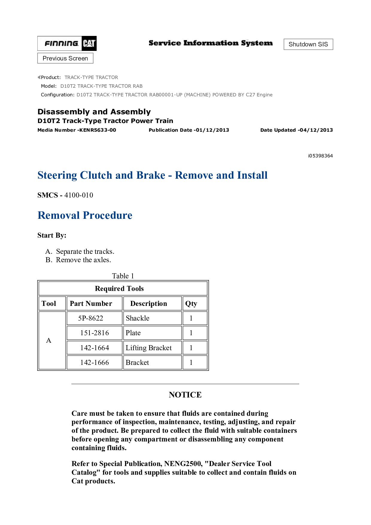
TRACTOR RAB Configuration: D10T2 TRACK-TYPE TRACTOR RAB00001-UP (MACHINE) POWERED BY C27 Engine Disassembly and Assembly D10T2 Track-Type Tractor Power Train Media Number -KENR5633-00 Publication Date -01/12/2013 Date Updated -04/12/2013 i07375092 Final Drive - Disassemble SMCS - 4050-015 Disassembly Procedure Start By: a. Remove the final drive. Refer to Disassembly and Assembly, "Final Drive - Remove". Note: Cleanliness is an important factor. Before you begin the disassembly procedure, the exterior of the components should be thoroughly cleaned. This will help to prevent dirt from entering the internal mechanism. Precision components can be damaged by contaminants or by dirt. Perform disassembly procedures on a clean work surface. Keep components covered and protected at all times. NOTICE Care must be taken to ensure that fluids are contained during performance of inspection, maintenance, testing, adjusting, and repair of the product. Be prepared to collect the fluid with suitable containers before opening any compartment or disassembling any component containing fluids. Refer to Special Publication, NENG2500, "Dealer Service Tool Catalog" for tools and supplies suitable to collect and contain fluids on Cat® products. Dispose of all fluids according to local regulations and mandates. Table 1 Required Tools